 Lapsed, fee not paid18 drawings
Hardware & Electronics · US 9,796,921 B2
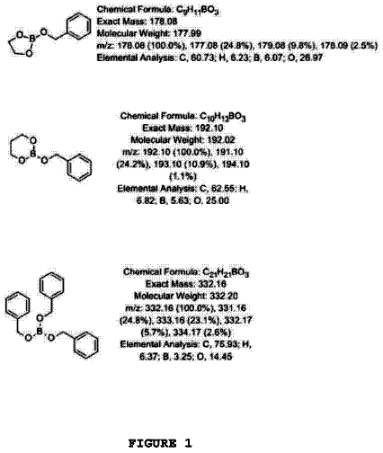
Boron compounds for use in scintillators and admixture to scintillators
The present disclosure is directed to liquid boron compounds for use in scintillation.
US 9,797,558 B2 · Assignee: Apple Inc. · Inventors: Kerr; Duncan R. et al.
Sheet 1 of 39 from the published document. All sheets in the USPTO PDF
A computing device is disclosed. The computing device includes a housing having an illuminable portion. The computing device also includes a light device disposed inside the housing. The light device is configured to illuminate the illuminable portion.
The present invention relates generally to a computing device. More particularly, the present invention relates to improved features for changing the appearance of a computing device. Most computing devices, including portable computers and desktop computers, give feedback to its user via a display screen or speakers. As is generally well known, display screens are used to display textual or graphical information to a user and speakers are used to output sound to the user. For example, display screens may be used to display a graphical user interface (GUI) and speakers may be used to output music or audio messages. Computing devices also give feedback to users via small indicators positioned on the computing device. By way of example, some indicators use light to indicate that a computing device (or the display screen of the computing device) is turned on/off or that a disk drive is read
1 of 39 drawing sheets so far from the published document, cropped to the drawing. Every sheet is in the USPTO PDF.
What the patent claimed, word for word. All of it is now free to use.
The present invention relates generally to a computing device. More particularly, the present invention relates to improved features for changing the appearance of a computing device.
Most computing devices, including portable computers and desktop computers, give feedback to its user via a display screen or speakers. As is generally well known, display screens are used to display textual or graphical information to a user and speakers are used to output sound to the user. For example, display screens may be used to display a graphical user interface (GUI) and speakers may be used to output music or audio messages. Computing devices also give feedback to users via small indicators positioned on the computing device. By way of example, some indicators use light to indicate that a computing device (or the display screen of the computing device) is turned on/off or that a disk drive is reading or writing data to a disk. Although displays, speakers and indicators work well, they are limited to the type of feedback they give a user. For example, while playing a movie with a DVD drive of a computing device, the display screen only outputs the video associated with the movie, the speaker only outputs the audio associated with the movie, and the indicator only indicates that a movie is playing the DVD drive. Thus, it would be desirable to provide additional feedback to a user.
Computing devices also have housings that enclose the components and circuitry associated with operating the computing devices. Housings generally serve to shield and protect the components and circuitry from adverse conditions such as impact and dust. In some cases, the housings are configured to surround all the components of the computing device while in other cases the housings are configured to surround individual or a subset of components. For example, a housing may be used to enclose the central processing unit (CPU), display screen, disk drive, and speaker to form a single unit. As another example, a plurality of different housings may be used to individually enclose the CPU, display screen, disk drive and speakers to form a plurality of individual units.
As is generally well known, housings for computing devices in particular product lines are typically manufactured with the same appearance, i.e., they look the same. For example, housings from a particular product line may have the same box-like shape and/or the same neutral color. This can be discouraging to computer users who desire computers that are more personalized or to computer users who desire computers that are different than another user's computer. Recently, manufacturers have attempted to remedy this problem by offering brightly colored or translucent housings for computing devices. For example, some computer and telephone manufacturers now sell a variety of housings, which have different colors and patterns. By way of example, the iMAC® computer, which is produced by Apple Inc., of Cupertino, Calif., is available in various colors and patterns.
Although these recent advances make substantial inroads to overcoming the same old appearance, the housings for the computing device remain passive structures that exhibit a non-adaptable or non-changing appearance. That is, a colored or patterned housing has a single color or pattern associated therewith that does not change overtime.
External lights have been used in some devices associated with displaying video to enhance the viewing experience of the video. Unfortunately, however, none of the external lights have been capable of changing the visual appearance of the device housing. That is, the external lights are typically located outside the periphery of the housing and are typically arranged to alter the environment in which the video is shown rather than the device housing itself (the appearance of the housing remains the same even with the use of lights).
Thus, there is a need for improvements in appearances of housings for computing devices.
The invention relates, in one embodiment, to a computing device. The computing device includes a housing for enclosing various internal components associated with the operation of the computing device. The computing device also includes an indicator assembly for indicating events associated with the computing device. The indicator assembly is configured to produce an indicator image at an outer surface of the housing when activated, and to eliminate the indicator image from the outer surface of the housing when deactivated.
The invention relates, in another embodiment, to a housing indicator system. The housing indicator system includes a housing having at least an inner bezel. The inner bezel has a light receiving recess that forms a reduced thickness portion. The reduced thickness portion is translucent. The housing indicator system also includes a light source disposed behind the housing. The light source is configured to illuminate the reduced thickness portion in order to form an indicator image at the outer surface of the inner bezel. The shape of the recess produces an indicator image of similar shape on the outer surface of the inner bezel.
The invention relates, in another embodiment, to a housing indicator system. The housing indicator system includes a housing having a clear outer layer and a translucent inner layer. The translucent inner layer includes a light receiving recess that forms a reduced thickness portion. The reduced thickness portion represents the area of the translucent layer that is illuminated. The housing indicator system also includes an indicator assembly. The indicator system includes a light device configured to provide light to the reduced thickness portion, a light barrier configured to prevent light from entering the translucent layer except at the reduced thickness portion and a light guide configured to direct light from the light source to the reduced thickness portion.
The invention relates, in another embodiment, to a computer system. The computer system includes a processor configured to generate light control signals. The computer system also includes a light feature operatively coupled to the processor. The light feature includes one or more light emitting diodes capable of emitting light in order to illuminate an illuminable housing of the computer system. The computer system also includes a light driver disposed between the processor and at least one of the LEDs. The light driver is configured to convert the light control signals into a stable continuous current for driving the light emitting diode. The magnitude of the current is based at least in part on the light control signal. The magnitude of the current affects the light intensity of the light emitting diode.
The invention relates, in another embodiment, to a method of illuminating a housing. The method includes generating a light control signal associated with a desired light intensity. The method also includes converting the light control signal into a voltage representative of the desired light intensity. The method further includes converting the voltage into a current representative of the desired light intensity. The current driving an LED so as to produce light. The method additionally includes directing the light from the LED through the housing such that an image is created at an outer surface of the housing.
The invention will be readily understood by the following detailed description in conjunction with the accompanying drawings, wherein like reference numerals designate like structural elements, and in which:
FIG. 1 is a simplified diagram of an electronic device, in accordance with one embodiment of the present invention.
FIG. 2 is a flow diagram of computer illumination processing, in accordance with one embodiment of the present invention.
FIG. 3 is a flow diagram of computer illumination processing, in accordance with another embodiment of the present invention.
FIG. 4 is a block diagram of a computing device, in accordance with one embodiment of the present invention.
FIG. 5 is a block diagram of a computer system, in accordance with one embodiment of the present invention.
FIG. 6 is a block diagram of a computer system, in accordance with another embodiment of the present invention.
FIG. 7 is a block diagram of a computer system, in accordance with another embodiment of the present invention.
FIG. 8 is a block diagram of a computer system, in accordance with another embodiment of the present invention.
FIG. 9 is a block diagram of a computer system, in accordance with another embodiment of the present invention.
FIG. 10 is a block diagram of a computer system, in accordance with another embodiment of the present invention.
FIG. 11 is a perspective diagram of a computer system, in accordance with one embodiment of the present invention.
FIG. 12 is a perspective diagram of a computer system, in accordance with another embodiment of the present invention.
FIG. 13 is a side view of a LED array, in accordance with one embodiment of the present invention.
FIGS. 14A and 14B are graphical illustrations showing color mixing via the LED array of FIG. 8 , in accordance with one embodiment of the present invention.
FIG. 15 is a perspective diagram of a computer, in accordance with one embodiment of the present invention.
FIG. 16 is a top view of a computer, in accordance with one embodiment of the present invention.
FIGS. 17A-C are broken away top views, in cross section, of a wall of a computer, in accordance with several embodiments of the present invention.
FIG. 18 is a perspective diagram of a computer, in accordance with one embodiment of the present invention.
FIG. 19 is a top view of a computer, in accordance with one embodiment of the present invention.
FIG. 20 is a perspective diagram of a computer, in accordance with one embodiment of the present invention.
FIGS. 21A-D are broken away top views, in cross section, of a wall of a computer, in accordance with several embodiments of the present invention.
FIG. 22 is a perspective diagram of a computer, in accordance with one embodiment of the present invention.
FIG. 23 is a top view of a computer, in accordance with one embodiment of the present invention.
FIG. 24 is a simplified diagram of a light source arrangement, in accordance with one embodiment of the present invention.
FIG. 25 is a simplified diagram of a light source arrangement, in accordance with one embodiment of the present invention.
FIG. 26 is a simplified diagram of a light source arrangement, in accordance with one embodiment of the present invention.
FIG. 27 is a top view of a computer having a light reflecting system, in accordance with one embodiment of the present invention.
FIG. 28 is a simplified diagram of a chameleonic electronic device, in accordance with one embodiment of the present invention.
FIG. 29 is a broken away diagram of a general purpose computer, in accordance with one embodiment of the present invention.
FIG. 30 is a block diagram of a computer system, in accordance with one embodiment of the present invention.
FIG. 31 is a perspective diagram of a computer system, in accordance with another embodiment of the present invention.
FIG. 32 is a simplified diagram of a computer network, in accordance with one embodiment of the present invention.
FIG. 33 is a flow diagram of illumination processing, in accordance with one embodiment of the present invention.
FIG. 34 is a perspective diagram of a monitor, in accordance with one embodiment of the present invention.
FIG. 35 is a perspective diagram of a monitor, in accordance with one embodiment of the present invention.
FIG. 36 is a perspective diagram of a monitor, in accordance with one embodiment of the present invention.
FIGS. 37A-37F are perspective diagrams of a monitor presenting a sequence, in accordance with one embodiment of the present invention.
FIGS. 38A-38B are simplified diagrams of a monitor presenting a sequence, in accordance with one embodiment of the present invention.
FIGS. 39A-39B are simplified diagrams of a monitor presenting a sequence, in accordance with one embodiment of the present invention.
FIG. 40 shows a computer system including a base and a monitor, in accordance with one embodiment of the present invention.
FIGS. 41A and 41B illustrate an indicator image as it appears on the surface of the housing when the indicator is on, and as it disappears from the surface of the housing when the indicator is off, in accordance with one embodiment of the present invention.
FIG. 42 is a diagram of an indicator, in accordance with one embodiment of the present invention.
FIG. 43 is a diagram of a housing indicator system, in accordance with one embodiment of the present invention.
FIG. 44 is a diagram of a housing indicator system, in accordance with one embodiment of the present invention.
FIG. 45 is a diagram of a housing indicator system, in accordance with one embodiment of the present invention.
FIG. 46 shows a fuzzy indicator image and a crisp indicator image, in accordance with embodiments of the present invention.
FIG. 47 is a diagram of a housing indicator system, in accordance with one embodiment of the present invention.
FIG. 48 is a diagram of a housing indicator system, in accordance with one embodiment of the present invention.
FIG. 49 is a diagram of a housing indicator system, in accordance with one embodiment of the present invention.
FIG. 50 is a diagram of a housing indicator system, in accordance with one embodiment of the present invention.
FIG. 51 is a diagram of a housing indicator system, in accordance with one embodiment of the present invention.
FIG. 52 is a diagram of a housing indicator system, in accordance with one embodiment of the present invention.
FIG. 53 is a diagram of a housing indicator system, in accordance with one embodiment of the present invention.
FIG. 54 is a diagram of the various layers of a computer system with a light feature, in accordance with one embodiment of the present invention.
FIG. 55 is a diagram of light assembly, in accordance with one embodiment of the present invention.
FIG. 56 is a diagram of light assembly, in accordance with one embodiment of the present invention.
FIG. 57 is a simplified diagram of a light driver, in accordance with one embodiment of the present invention.
FIG. 58 is an exemplary circuit diagram of light driver, in accordance with one embodiment of the present invention.
FIG. 59 is an exemplary circuit diagram of light switch, in accordance with one embodiment of the present invention.
FIG. 60 is a diagram of a graphical user interface, in accordance with one embodiment of the present invention.
The invention pertains to electronic devices capable of changing their ornamental or decorative appearance, i.e., the outer appearance as seen by a user. The electronic devices generally include an illuminable housing. The illuminable housing, which includes at least one wall configured for the passage of light, is configured to enclose, cover and protect a light arrangement as well as functional components of the electronic device. For example, in the case of a desktop computer, the functional components may include a processor for executing instructions and carrying out operations associated with the computer, and in the case of a display monitor, the functional components may include a display for presenting text or graphics to a user. The light arrangement, which generally includes one or more light sources, is configured to produce light for transmission through the light passing wall (or walls) of the illuminable housing. As should be appreciated, the transmitted light illuminates the wall (s) thus giving the wall a new appearance, i.e., the color, pattern, behavior, brightness and/or the like. That is, the transmitted light effectively alters the ornamental or decorative appearance of the electronic device. By way of example, a light source capable of producing green light may cause the light passing wall to exude green.
In most cases, the light is controlled so as to produce a light effect having specific characteristics or attributes. As such, the electronic device may be configured to provide additional feedback to the user of the electronic device and to give users the ability to personalize or change the look of their electronic device on an on-going basis. That is, a housing of the electronic device is active rather than passive, i.e., the housing has the ability to adapt and change. For example, the light may be used to exhibit a housing behavior that reflects the desires or moods of the user, that reflects inputs or outputs for the electronic device, or that reacts to tasks or events associated with operation of the electronic device.
It is contemplated that the present invention may be adapted for any of a number of suitable and known consumer electronic products that perform useful functions via electronic components. By way of example, the consumer electronic products may relate to computing devices and systems that process, send, retrieve and/or store data. The computing devices and systems may generally relate to desktop computers (both segmented and all-in-one machines) that sit on desks, floors or other surfaces, portable computers that can be easily transported by a user, or handheld computing devices. By way of example, portable computers include laptop computers, and handheld computing devices include personal digital assistants (PDAs) and mobile phones.
Embodiments of the invention are discussed below with reference to FIGS. 1-26 . However, those skilled in the art will readily appreciate that the detailed description given herein with respect to these figures is for explanatory purposes as the invention extends beyond these limited embodiments.
FIG. 1 is a simplified diagram of a chameleonic electronic device 10 , in accordance with one embodiment of the invention. The word “chameleonic” refers to the fact that the electronic device 10 has the ability to alter its visual appearance.
The chameleonic electronic device 10 generally includes a housing 12 configured to form an external protective covering of the chameleonic electronic device 10 and a light system 14 configured to adjust the illuminance or pigmentation of the housing 12 . The housing 12 of the chameleonic electronic device 10 surrounds and protects internal components 18 disposed therein. The internal components 18 may be a plurality of electrical components that provide specific functions for the chameleonic electronic device 10 . For example, the internal electrical components 18 may include devices for generating, transmitting and receiving data associated with operating the electronic device. In one embodiment, the chameleonic electronic device is a component of a computer system, as for example, a general purpose computer. As such, the internal electrical components may include a processor, memory, controllers, I/O devices, displays and/or the like.
The chameleonic electronic device 10 is configured to change its visual appearance via light. That is, the housing 12 is configured to allow the passage of light and the light system 14 is configured to produce light for transmission through the housing 12 . In one embodiment, the light system 14 includes a light arrangement (not shown). The light arrangement, which is disposed inside the housing 12 and which includes at least one light source, is configured to emit light 20 incident on the inner surface of the housing 12 . As should be appreciated, light 22 that is transmitted through the wall of the housing 12 changes the look of the housing 12 and thus the visual appearance of the chameleonic electronic device 10 . By way of example, the light 20 may cause the housing 12 to exude a specific brightness such as intense or dull light, a specific color such as green, red or blue, a specific pattern such as a rainbow or dots, or a changing behavior such as a strobe effect or fading in/out.
In some cases, the light system 14 is arranged to cooperate with the electrical components 18 . For example, events associated with the electrical components 14 may be monitored, and the light system 14 may be controlled based on the monitored events. As such, an illumination effect corresponding to a specific event may be produced. For example, the housing 12 may be configured to exude a blinking red coloration when an event has been implemented. Although the light system 14 may cooperate with the electrical components 18 , it should be understood that the electrical components 18 and the light system 14 are distinct devices serving different functions. That is, the electrical components 18 are generally configured to perform functions relating to operating the chameleonic electronic device 10 , and the light system 14 is generally configured to change the appearance of the housing 12 thereof.
FIG. 2 is a flow diagram of computer illumination processing 30 , in accordance with one embodiment of the invention. The computer illumination processing 30 is performed by a computer (or computer system) to provide the computer with an illumination effect, as for example, the illumination of a housing relating to the computer. The illumination effect for the housing is provided by a light system. Typically, the light system is internal to the housing being illuminated. In one embodiment, the computer corresponds to a general purpose computer such as an IBM compatible computer or an Apple compatible computer. By way of example, the Apple compatible computer may include different models such as the iMac, G3, G4, Cube, iBook, or Titanium models, which are manufactured by Apple Inc. of Cupertino, Calif.
The computer illumination processing 30 begins at block 32 where events associated with a computer are monitored. In one embodiment, the events being monitored are identified by an operating system or a microprocessor utilized within the computer. The events can take many forms such as operating system events or microprocessor events. By way of example, the events may relate to signals, conditions or status of the computer.
Following block 32 , the process proceeds to block 34 where a light system, associated with the computer, is controlled 34 based on the monitored events to provide a housing, also associated with the computer, with an ornamental appearance. In other words, the computer illumination processing 30 operates to provide the housing of the computer with a dynamic ornamental appearance that varies in accordance with the monitored events of the computer. By way of example, the housing and light system may generally correspond to the housing and light system described in FIG. 1 . After the light system is controlled at block 34 , the computer illumination processing 30 is complete and ends. It should be noted, however, that the processing can be repeatedly performed or performed whenever a new event occurs.
FIG. 3 is a flow diagram of computer illumination processing 40 , in accordance with another embodiment of the invention. The computer illumination processing 40 is performed by a computer system (or computer) to provide the computer system with an illumination effect, as for example, the illumination of a housing associated with the computer system. The illumination effect for the housing is provided by a light system. Typically, the light system is internal to the housing being illuminated. In one embodiment, the computer system corresponds to a general purpose computer such as an IBM compatible computer or an Apple compatible computer. By way of example, the Apple compatible computer may include different models such as the iMac, G3, G4, Cube, iBook, or Titanium models, which are manufactured by Apple Inc. of Cupertino, Calif.
The computer illumination processing 40 generally begins at block 42 where computer system hardware and software is monitored. Here, one or more devices, units or systems associated with the computer system can be monitored. By way of example, the devices or systems being monitored can include one or more of a microprocessor, an operating system, an application or utility program, or input/output (I/O) devices. After block 42 , the process proceeds to block 44 where status information associated with the devices, units or systems is obtained from the monitoring. By way of example, status information may correspond to I/O connectivity status, wireless connectivity status, network connectivity status, processor status (e.g., sleep, shutdown), program status (e.g., errors, alerts, awaiting inputs, received new mail, loading), remote status (e.g., retrieving information from the internet), and/or the like.
After block 44 , the process proceeds to block 46 where illumination characteristics are determined. Illumination characteristics generally refer to how a housing associated with the computer is illuminated to produce an ornamental appearance. The illumination characteristics are generally based on the status information and predetermined configuration information. In one embodiment, the predetermined configuration information identifies a type and nature of the illumination (e.g., which lights are operated, how long the light sources are operated, what color the light source output, etc.) that is to be provided for a specific status information. By way of example, a blinking red coloration may be identified when a program status such as an error is monitored.
In one embodiment, the predetermined configuration information is stored in a database. Thus, the computer consults the information held in the database in order to determine the illumination characteristics for a specific event. The predetermined configuration information stored in the database may be accessed by a user through a light control menu, which may be viewed on a display screen as part of a GUI interface. The light control menu may include light control settings pertaining to one or more events of the computer. In fact, the light control menu may serve as a control panel for reviewing and/or customizing the light control settings, i.e., the user may quickly and conveniently review the light control settings and make changes thereto. Once the user saves the changes, the modified light control settings will be employed (e.g., as predetermined configuration information) to handle future events transmitted and/or received through the computer.
After the illumination characteristics have been determined, the process proceeds to block 48 where driving signals for light elements associated with the light system are determined in accordance with the illumination characteristics. Typically, the light elements are arranged within a portion of the computer system. For example, the light elements could be arranged within a primary housing of the computer system. In another embodiment, the light elements could be arranged within a housing for a peripheral device associated with the computer system. After the driving signals are determined, the process proceeds to block 50 where the driving signals are used to control the light elements. For example, the driving signals may actuate one or more of the light elements so as to emit light incident on an inner surface of a housing. Once the drive signals control the light elements, the ornamental appearance of the housing is thus altered. Typically, the housing has one or more portions that are configured for allowing the passage of light, thereby causing the light to be transmitted therethrough which effectuates the ornamental appearance of the housing.
After using the driving signals, the process proceeds to block 52 where a decision is made as to whether the computer illumination processing 40 should end. When the decision 52 determines that the computer illumination processing 40 should not end, the computer illumination processing 40 returns to repeat the operation 42 and subsequent operations so that the illumination characteristics can be continuously updated in accordance with the status information. On the other hand, when the decision 52 determines that the computer illumination processing 40 should end, the computer illumination processing 40 is complete and ends. In general, the computer illumination processing 40 can be repeatedly performed or performed in an event driven manner.
FIG. 4 is a block diagram of a computing device 60 , in accordance with one embodiment of the present invention. By way of example, the computing device 60 may correspond to the chameleonic electronic device 10 shown in FIG. 1 . The computing device 60 generally includes a variety of computer components 62 , which as an example may correspond to the electrical components 18 in FIG. 1 . The computer components 62 are generally configured to process, retrieve and store data associated with the computing device 60 . By way of example, the computer components 62 may include a CPU (central processing unit), I/O controllers, display controllers, memory and the like. The computer components may also include operating systems, utility programs, application programs and/or the like.
The computing device 60 also includes an event monitor 64 operatively coupled to the computer components 62 . The event monitor 64 is configured to track specific data through the computer components. For example, the event monitor 64 may be configured to track input data 66 and/or output data 68 . Although shown outside the computer components, the input data and output data may correspond to internal inputs and outputs generated between individual parts of the computer components as well as to external inputs and outputs generated outside the computer components. By way of example, interior inputs/outputs may relate to data that is passed between a CPU and an I/O controller, and exterior inputs/outputs may relate to data that is passed between an I/O controller and an I/O device such as a keyboard, mouse, printer and the like. In one embodiment, the event monitor is part of the functionality provided by the computer components. For example, the event monitor may be included in the CPU. In another embodiment, the event monitor provides functionality independent of the computer components. For example, the event monitor may be a separate processor chip that is connected to a chip housing the CPU.
The computing device 60 also includes a light effect manager 70 operatively coupled to the event monitor 64 . The light effect manager 70 is configured to direct light control signals to a light arrangement 72 , and more particularly to a plurality of light elements 74 disposed inside a housing. The light control signals are generally based on the events tracked by the event monitor 64 . That is, as events are processed by the computer components 62 , the light effect manager 70 directs light control signals to the light elements 74 . The light control signals carry illumination characteristics pertaining to the desired light effect that each of the light elements is to provide at the housing. That is, the light control signals sent to each of the light elements may cause the light elements to emit the same light effect (e.g., all emitting green light at the same intensity) or a different light effect (e.g., one element emitting green light while another emits blue light). These light elements 74 work together to produce a light effect that dynamically changes the ornamental appearance of the housing.
In one embodiment, the light effect manger 70 is configured to determine illumination characteristics based on the specific events (or data) monitored and the corresponding predetermined configuration information. As explained earlier, predetermined configuration information relates to information that is selected by a user and stored. In one embodiment, the light effect manager 70 is part of the functionality provided by the computer components 62 . For example, the light effect manager 70 may be included in the processor chip of the computing device 60 that also includes the CPU. In another embodiment, the light effect manager 70 provides functionality independent of the computer components. For example, the light effect manager 70 may be a separate processor chip that is connected to a separate chip housing the CPU.
FIG. 5 is a block diagram of a computer system 100 , in accordance with one embodiment of the present invention. By way of example, the computer system 100 may correspond to the electronic device 10 shown in FIG. 1 . The computing system 100 generally includes a processor 102 (e.g., CPU or microprocessor) configured to execute instructions and to carry out operations associated with the computer system 100 . By way of example, the processor 102 may execute instructions under the control of an operating system or other software.
The computing system 100 also includes an input/output (I/O) controller 104 that is operatively coupled to the processor 102 . The I/O controller 104 is generally configured to control interactions with one or more I/O devices 106 that can be coupled to the computing system 100 . The I/O controller 104 generally operates by exchanging data between the computing system 100 and the I/O devices 106 that desire to communicate with the computing system 100 . In some cases, the I/O devices 106 may be connected to the I/O controller 104 through wired connections such as through wires or cables. In other cases, the I/O devices 106 may be connected to the I/O controller 104 through wireless connections. By way of example, the I/O devices 106 may be internal or peripheral devices such as memory, disk drives, keyboards, mice, printers, scanners, speakers, video cameras, MP3 players and the like. The I/O devices 106 may also be network-related devices such as network cards or modems.
The computing system 100 additionally includes a display controller 108 that that is operatively coupled to the processor 102 . The display controller 108 is configured to process display commands to produce text and graphics on a display device 110 . By way of example, the display 110 may be a monochrome display, color graphics adapter (CGA) display, enhanced graphics adapter (EGA) display, variable-graphics-array (VGA) display, super VGA display, liquid crystal display (LCD), cathode ray tube (CRT), plasma displays and the like.
The computing system 100 further includes a light source controller 112 that is operatively coupled to the processor 102 . The light source controller 112 generally provides processing of light commands from the processor 102 to produce light 116 in a controlled manner via a light source 114 . By way of example, the light source 114 may be one or more light emitting diodes (LED), light emitting semiconductor dies, lasers, incandescent light bulbs, fluorescent light bulbs, neon tubes, liquid crystal displays (LCD), and the like, that are arranged to produce light and more particularly colored light. The light source 114 is generally disposed inside an enclosure 120 that covers and protects some aspect of the computing system 100 . More particularly, the enclosure 120 can cover and protect one or more computer components having functionality used in the operation of the computing system 100 . By way of example, the enclosure 120 may be configured to cover one or more of the components described above. The enclosure 120 generally includes a wall 122 that is configured for transmitting light therethrough. As such, at least a portion of the light 116 , which is made incident on the wall 122 via the light source 114 , passes through the wall 122 , thereby producing a light effect 124 that alters the visual appearance of the enclosure 120 and thus the visual appearance of the computing system 100 .
Light effects are generally defined as the way in which the light 116 , produced by the light source 114 and controlled by the light source controller 112 , acts or influences the enclosure 120 . Metaphorically speaking, the enclosure is the canvas, the light is the paint, and the light effect is the painting. Accordingly, in some cases, the light effect is arranged to cover the entire wall 122 while in other cases, the light effect is arranged to cover only a portion of the wall 122 .
Light effects may be categorized as static (non-changing over time) or dynamic (changing over time). By way of example, static light effects may cause the enclosure to continuously exude a fixed color such as blue, a fixed shade of a color such as light blue, a fixed pattern or artistic design such as rainbow, stripes, dots, flowers and the like, or a fixed orientation such as a color or pattern located in a specific region of the enclosure. In addition, dynamic light effects may cause the enclosure to exude different colors, intensities or patterns at different times and in different orientations. That is, the coloration, intensities, patterns and position thereof may vary. For example, dynamic light effects may include light effects that change at least partially from a first color, intensity or pattern to a second color, intensity or pattern (e.g., from red to blue to light blue to rainbow, blinking on and off or fading in and out), that change regionally around the enclosure (e.g., moving from a first side to a second side of the enclosure, moving from center to outer, moving around the enclosure in a continuous fashion, a pattern that starts at a certain point on the enclosure and radiates out, etc.), or any combination thereof.
In one embodiment, computer illumination processing may be performed by the computer system when events associated with the computer system occur in or outside the system. The illumination processing generally provides the computer system with an illumination effect, as for example, the illumination of a housing associated with the computer system. In general, illumination processing includes monitoring events associated with the computer system (e.g., software or hardware) and controlling the light source based on the monitored events so as to provide a housing associated with the computer system with an ornamental appearance corresponding to the monitored event. The events being monitored are generally identified by an operating system or a microprocessor utilized within the computer system. The events can take many forms such as operating system events or microprocessor events. By way of example, the events may relate to signals, conditions or status of the computer system. Examples of illumination processing are described in greater detail in U.S. application Ser. No. 10/075,520 filed Feb. 13, 2002, now U.S. Pat. No. 7,113,196 issued Sep. 26, 2006 and entitled, “COMPUTING DEVICE WITH DYNAMIC ORNAMENTAL APPEARANCE”, which is incorporated herein by reference.
Although not shown in FIG. 5 , the computer system may include other components such as buses, bridges, connectors, wires, memory, and the like. As is generally well known, buses provide a path for data to travel between components of the computer system 100 . In addition, bridges serve to perform adjustments necessary to bridge communication between different buses, i.e., various buses follow different standards. Further, memory provides a place to hold data that is being used by the computer system. By way of example, memory may be a Read-Only Memory (ROM) or a Random-Access Memory (RAM). RAM typically provides temporary data storage for use by at least the processor 102 , and ROM typically stores programming instructions for use with the processor 102 .
The description continues in the full USPTO document.
About 6,368 words. The USPTO PDF has it with every drawing.
Fees are due 3.5, 7.5 and 11.5 years after grant. This patent expired on October 24, 2025, so the fee marked "not paid" was the one that went unpaid.
Active enclosure for computing device
Filed Feb 2004 · published Aug 2004Active enclosure for computing device
Filed Feb 2004 · granted Aug 2010ACTIVE ENCLOSURE FOR COMPUTING DEVICE
Filed Jul 2009 · published Nov 2009ACTIVE ENCLOSURE FOR COMPUTING DEVICE
Filed Jul 2009 · published Nov 2009Active enclosure for computing device
Filed Jul 2009 · granted Oct 2011Active enclosure for computing device
Filed Jul 2009 · granted Apr 2012ACTIVE ENCLOSURE FOR COMPUTING DEVICE
Filed Apr 2010 · published Aug 2010Active enclosure for computing device
Filed Apr 2010 · granted Oct 2011ACTIVE ENCLOSURE FOR COMPUTING DEVICE
Filed Feb 2012 · published May 2012Active enclosure for computing device
Filed Feb 2012 · granted Sep 2012ACTIVE ENCLOSURE FOR COMPUTING DEVICE
Filed Aug 2012 · published Nov 2012Active enclosure for computing device
Filed Aug 2012 · granted Mar 2013Active Enclosure for Computing Device
Filed Feb 2013 · published Jun 2013Active enclosure for computing device
Filed Feb 2013 · granted May 2014Active Enclosure for Computing Device
Filed Apr 2014 · published Aug 2014Active enclosure for computing device
Filed Apr 2014 · granted Oct 2017Earlier publications, parents and continuations. None of them can still be enforced, or this patent would not be listed.
Prior art cited by the examiner or applicant. Useful when you check your own idea for novelty.
Everything on this page comes from the documents linked above.


