 Lapsed, fee not paid17 drawings
Vehicles & Drones · US 9,797,310 B2
Heat pipe temperature management system for a turbomachine
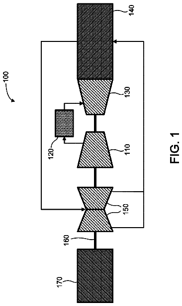
A turbomachine includes a compressor having an inter-stage gap between adjacent rows of rotor blades and stator vanes.
US 9,797,320 B2 · Assignee: MITSUBISHI HEAVY INDUSTRIES, LTD. · Inventors: Yokoyama; Takao et al.
Sheet 1 of 9 from the published document. All sheets in the USPTO PDF
An object is to provide an engine system including an intake bypass device whereby it is possible to expand the operation range of a compressor without causing the output of a turbine to become insufficient. An engine system includes an intake bypass device including a bypass channel connecting a downstream side of a compressor of a turbocharger in an intake channel and an upstream side of a turbine of the turbocharger in an exhaust channel, a bypass valve disposed in the bypass channel and configured to control a flow of compressed intake air in the bypass channel, and a heating unit for heating the compressed intake air flowing through the bypass channel.
As a technique to improve an output of an engine, a method (supercharging) of compressing intake air with a turbocharger and supplying an engine with the compressed intake air is known, and widely used in engines for automobiles and the like. Especially in recent years, supercharging is applied to a wide operation range of from a low-output range to a high-output range, in view of the regulations on exhaust gas and fuel consumption rate that have become increasingly stricter. On the other hand, in a turbocharger, surging may occur transitionally depending on the operation state of the turbocharger. Occurrence of surging in a turbocharger may lead to breakage of various devices such as an impeller, and thus needs to be prevented as much as possible. In view of this, a technique to widen the operation range of a compressor while avoiding occurrence of surging has been required. A known tec
1 of 9 drawing sheets so far from the published document, cropped to the drawing. Every sheet is in the USPTO PDF.
What the patent claimed, word for word. All of it is now free to use.
The present disclosure relates to an engine system including an intake bypass device for guiding a part of compressed intake air compressed by a compressor to an upstream side of a turbine bypassing an engine body.
As a technique to improve an output of an engine, a method (supercharging) of compressing intake air with a turbocharger and supplying an engine with the compressed intake air is known, and widely used in engines for automobiles and the like. Especially in recent years, supercharging is applied to a wide operation range of from a low-output range to a high-output range, in view of the regulations on exhaust gas and fuel consumption rate that have become increasingly stricter.
On the other hand, in a turbocharger, surging may occur transitionally depending on the operation state of the turbocharger. Occurrence of surging in a turbocharger may lead to breakage of various devices such as an impeller, and thus needs to be prevented as much as possible. In view of this, a technique to widen the operation range of a compressor while avoiding occurrence of surging has been required.
A known technique to widen the operation range of a compressor while avoiding occurrence of surging is an intake bypass device which guides a part of compressed intake air compressed by a compressor to flow to an upstream side of a turbine bypassing an engine body, as disclosed in Patent Document 1, for instance.
The intake bypass device of Patent Document 1 includes a bypass channel connecting a downstream side of the compressor in an intake channel and an upstream side of the turbine in an exhaust channel, and a flow-rate adjustment valve disposed in the bypass channel. The flow-rate adjustment valve is controlled so that the valve opening degree increases when the operation point of the compressor enters the vicinity of a surge region. When the valve opening degree of the flow-rate adjustment valve increases, the flow rate of the compressed intake air guided to flow to the upstream side of the turbine via the bypass channel increases. As a result, the turbine output increases and the operation flow rate of the compressor increases, which makes it possible to prevent surging. CITATION LIST Patent Literature
Patent Document 1: JP2000-64844A SUMMARY Problems to be Solved
However, in the intake bypass device disclosed in the above described Patent Document 1, compressed intake air having a relatively low temperature merges with exhaust gas having a high temperature discharged from the engine, and the turbine is driven by the exhaust gas having incorporated the compressed intake air. Thus, the energy of exhaust gas that drives the turbine may decrease, and the output of the turbine may be insufficient.
At least one embodiment of the present invention was made in view of the above conventional problem, and an object of the at least one embodiment is to provide an engine system including an intake bypass device whereby it is possible to widen an operation range of a compressor without causing an output of a turbine to become insufficient. Solution to the Problems
An engine system according to at least one embodiment of the present invention comprises: an engine body; an intake channel for supplying intake air to the engine body; an exhaust channel through which exhaust gas discharged from the engine body flows; a turbocharger including a turbine disposed in the exhaust channel and driven by energy of the exhaust gas discharged from the engine body, and a compressor disposed in the intake channel and driven coaxially with the turbine; and an intake bypass device for guiding a part of compressed intake air compressed by the compressor to flow to an upstream side of the turbine bypassing the engine body. The intake bypass device includes a bypass channel connecting a downstream side of the compressor in the intake channel and an upstream side of the turbine in the exhaust channel, a bypass valve disposed in the bypass channel and configured to control a flow of the compressed intake air in the bypass channel, and a heating unit for heating the compressed intake air flowing through the bypass channel.
In the engine system including the above intake bypass device, the intake bypass device includes the heating unit for heating the compressed intake air flowing through the bypass channel, and is configured so that the compressed intake air having been heated is guided to flow to the upstream side of the turbine. Thus, it is possible to prevent a decrease in the energy of the exhaust gas for driving the turbine and to prevent shortage of the output of the turbine.
In some embodiments, the heating unit is configured to utilize the exhaust gas discharged from the engine body as a heat source for heating the compressed intake air flowing through the bypass channel.
According to the above embodiment, it is possible to heat the compressed intake air flowing through the bypass channel by effectively utilizing the thermal energy of the exhaust gas discharged from the engine body without providing an additional heat source such as a heater separately.
In some embodiments, the heating unit comprises a turbine housing of the turbine forming at least a part of an inner wall surface of the bypass channel, in a partial section of the bypass channel.
According to the above embodiment, it is possible to heat the compressed intake air flowing through the bypass channel using the thermal energy of the exhaust gas flowing through the turbine housing. In addition, since it is possible to cool the turbine housing with the compressed intake air flowing through the bypass channel, it is no longer necessary to use an expensive heat-resistant material for the turbine housing, which makes it possible to reduce the cost.
In the above embodiment, at least a part of the turbine housing has a dual structure including an inner housing formed of sheet metal and an outer housing formed of sheet metal covering the inner housing. Further, the space defined by the inner housing and the outer housing forms a partial section of the bypass channel in the above embodiment.
According to the above embodiment, the space defined by the inner housing and the outer housing constitutes a partial section of the bypass channel in the above embodiment, and the compressed intake air flows through this space, which makes it possible to heat the compressed intake air and cool the turbine housing efficiently.
In some embodiments, the engine system further comprises an exhaust-gas purification device for purifying the exhaust gas discharged from the engine body. The exhaust-gas purification device is disposed on a downstream side of the turbine in the exhaust channel. The heating unit comprises the exhaust channel on a downstream side of the exhaust-gas purification device forming at least a part of an inner wall surface of the bypass channel, in a partial section of the bypass channel.
According to the above embodiment, it is possible to heat the compressed intake air flowing through the bypass channel using the thermal energy of the exhaust gas flowing through the exhaust channel. In addition, since the remaining thermal energy of the exhaust gas after having driven the turbine and passed through the exhaust-gas purification device to heat a medium is recovered, it is possible to heat the compressed intake air without affecting the output of the turbine or the purification performance of the exhaust-gas purification device.
In the above embodiments, at least a part of the exhaust channel on the downstream side of the exhaust-gas purification device has a dual structure including an inner exhaust duct through which the exhaust gas flows and an outer exhaust duct covering the inner exhaust duct. Further, a space defined by the inner exhaust duct and the outer exhaust duct forms a partial section of the bypass channel.
According to the above embodiment, the space defined by the inner exhaust duct and the outer exhaust duct constitutes a partial section of the bypass channel in the above embodiment, and the compressed intake air flows through this space, which makes it possible to heat the compressed intake air efficiently.
In some embodiments, the heating unit comprises an exhaust manifold connecting the engine body and the exhaust channel forming at least a part of an inner wall surface of the bypass channel, in a partial section of the bypass channel.
According to the above embodiment, it is possible to heat the compressed intake air flowing through the bypass channel using the thermal energy of the exhaust gas flowing through the exhaust manifold. In addition, since the heat is exchanged with the high-temperature exhaust gas flowing through the exhaust manifold, it is no longer necessary to use an expensive thermal-resistant material for the exhaust manifold and the exhaust channel or the like disposed on the downstream side of the exhaust manifold, which makes it possible to reduce the cost.
In the above embodiments, at least a part of the exhaust manifold has a dual structure including an inner exhaust manifold through which the exhaust gas flows and an outer exhaust manifold covering the inner exhaust manifold. Further, a space defined by the inner exhaust manifold and the outer exhaust manifold forms a partial section of the bypass channel.
According to the above embodiment, the space defined by the inner exhaust manifold and the outer exhaust manifold constitutes a partial section of the bypass channel in the above embodiment, and the compressed intake air flows through this space, which makes it possible to heat the compressed intake air and cool the exhaust manifold efficiently.
In some embodiments, the intake bypass device includes a turbo control unit including a control part and a signal input part separate and independent from an engine control unit for controlling an operation state of the engine body, and the turbo control unit includes a bypass-valve control part for controlling a valve opening degree of the bypass valve.
In accordance with the improvement of the engines in recent years, the control logic and hardware configuration of an engine controller is becoming increasingly complicated. Thus, if the bypass-valve control part for controlling the valve opening degree of the bypass valve is mounted to the engine controller, the control logic and hardware configuration of the engine would become even more complicated. Further, if a quickly-changing transitional phenomenon like surging is to be controlled by an engine controller having a control logic and hardware configuration which are complicated, communication delay of the engine controller may be a problem.
Thus, as in the present embodiment, it is possible to prevent the engine control unit from becoming complicated by mounting the bypass-valve control part to the turbo control unit configured separately from the engine control unit.
In the above embodiment, the turbo control unit includes a turbo signal input part into which a sensor signal related to an operation state of the engine such as a boost pressure, an intake flow rate, an engine rotation speed, and a turbo rotation speed is inputted, and a turbo control part including an operation-point computing part and the bypass-valve control part, the operation-point computing part being configured to compute an operation point of the compressor on the basis of the sensor signal inputted into the turbo signal input part. Further, the bypass-valve control part is configured to control the valve opening degree of the bypass valve to increase when the operation point computed by the operation-point computing part is in the vicinity of a surge region.
According to the above embodiment, since the turbo control unit itself computes the operation point of the compressor and controls the valve opening degree of the bypass valve on the basis of the computed operation point, it is possible to control the bypass valve quickly while avoiding an influence of communication delay as compared to a case where the engine control unit controls the valve opening degree of the bypass valve.
In the above embodiment, the sensor signal comprises a sensor signal related to a boost pressure of the compressed intake air compressed by the compressor and to an intake flow rate of the intake air flowing through the compressor.
According to the above embodiment, it is possible to compute the operation point of the compressor from the boost pressure and the intake flow rate accurately. Advantageous Effects
According to at least one embodiment of the present invention, it is possible to provide a DPF regeneration control device whereby it is possible to prevent clogging of a DOC more efficiently than the conventional technique, and to recover the DOC securely from the clogging even if the DOC is actually clogged.
FIG. 1 is an overall configuration diagram of an engine system including an intake bypass device according to the first embodiment of the present invention.
FIG. 2 is a compressor map showing the operation characteristics of a compressor.
FIG. 3 is a block diagram for describing the function of a turbo ECU.
FIG. 4 is an overall configuration diagram of an engine system including an intake bypass device according to the second embodiment of the present invention.
FIG. 5 is a schematic cross-sectional view illustrating an example of a heating unit of the second embodiment.
FIG. 6 is a schematic cross-sectional view illustrating another example of a heating unit of the second embodiment.
FIG. 7 is an overall configuration diagram of an engine system including an intake bypass device according to the third embodiment of the present invention.
FIG. 8 is a schematic cross-sectional view illustrating an example of a heating unit of the third embodiment.
FIG. 9 is a schematic cross-sectional view illustrating another example of a heating unit of the third embodiment.
FIG. 10 is an overall configuration diagram of an engine system including an intake bypass device according to the fourth embodiment of the present invention.
FIG. 11 is a schematic cross-sectional view illustrating an example of a heating unit of the fourth embodiment.
FIG. 12 is a schematic cross-sectional view illustrating another example of a heating unit of the fourth embodiment.
Embodiments of the present invention will now be described in more detail with reference to the accompanying drawings.
However, the scope of the present invention is not limited to the following embodiments. It is intended that dimensions, materials, shapes, relative positions and the like of components described in the embodiments shall be interpreted as illustrative only and not limitative of the scope of the present invention. First Embodiment
FIG. 1 is an overall configuration diagram of an engine system including an intake bypass device according to the first embodiment of the present invention.
As illustrated in FIG. 1 , the engine system 1 of the present embodiment at least includes an engine body 2 , an intake channel 4 for supplying intake air to cylinders 2 a of the engine body 2 , an exhaust channel 6 for carrying exhaust gas discharged from the cylinders 2 a of the engine body 2 , a turbocharger 12 for compressing intake air to be supplied to the engine body 2 , and an intake bypass device 20 for guiding a part of the compressed intake air compressed by the turbocharger 12 to the exhaust channel 6 bypassing the engine body 2 .
The engine body 2 includes a plurality of cylinders 2 a . The engine body 2 and the intake channel 4 are connected to each other via an intake manifold 5 , and the intake manifold 5 distributes the intake air flowing through the intake channel 4 to each of the plurality of cylinders 2 a . Further, the engine body 2 and the exhaust channel 6 are connected to each other via an exhaust manifold 7 , and the exhaust manifold 7 collects the exhaust air discharged from the plurality of cylinders 2 a into the exhaust channel 6 .
The turbocharger 12 includes a turbine 8 disposed in the exhaust channel 6 , and a compressor 10 disposed in the intake channel 4 and coupled to the turbine 8 via a rotor to be driven coaxially with the turbine 8 . The turbine 8 is driven by exhaust energy of the exhaust gas discharged from the engine body 2 , and thereby the compressor 10 is coaxially driven, so as to compress the intake air flowing through the intake channel 4 .
Further, on the upstream side of the compressor 10 of the intake channel 4 , an airflow meter 31 for measuring an intake flow rate is disposed. Further, on the downstream side of the compressor 10 of the intake channel 4 , a pressure sensor 33 for measuring a boost pressure of the compressed intake air is disposed.
The intake bypass device 20 includes a bypass channel 14 connecting the downstream side of the compressor 10 in the intake channel 4 and the upstream side of the turbine 8 in the exhaust channel 6 , a bypass valve 16 disposed in the bypass channel 14 , and a heating unit 18 for heating the compressed intake air flowing through the bypass channel 14 .
The bypass valve 16 of the present embodiment is configured as a flow-rate control valve for controlling the flow rate of the compressed intake air guided to flow to the exhaust channel 6 from the intake channel 4 . The valve opening degree of the bypass valve 16 is controlled by a turbo ECU (turbo control unit) 24 described below, so that surging does not occur in the compressor 10 . In the present invention, the type of the bypass valve 16 is not limited to a flow-rate control valve. It is sufficient if the bypass valve 16 can at least prevent a backward flow of the exhaust gas from the exhaust channel 6 to the intake channel 4 , and the bypass valve 16 may be a check valve or the like.
FIG. 2 is a compressor map showing the operation characteristics of a compressor. In the drawing, x-axis is the flow rate and y-axis is the pressure ratio of the pressure at the inlet to that at the outlet of the compressor 10 . The reference signs N 1 , N 2 , N 3 in the drawing each represent the rotation speed of the compressor.
As illustrated in FIG. 2 , when the compressor 10 is operating at a small flow rate and at a high pressure ratio, the operating point P 1 may shift to the left side of the surge line to enter the surge region. The operating point (operation line) of the compressor 10 entering the surge region represents occurrence of surging in the compressor 10 . Thus, when the operation point (operation line) of the compressor 10 is in the vicinity of the surge region, the bypass valve 16 is controlled to have a large valve-opening degree, to increase the flow rate of the compressed intake air guided to flow to the exhaust channel 6 from the intake channel 4 . In this way, the turbine output increases and the operation flow rate of the compressor 10 increases (Q 1 to Q 2 ), and thereby the operation point P 2 shifts out of the surge region. As a result, surging is prevented.
FIG. 3 is a block diagram for describing the function of a turbo ECU.
The turbo ECU 24 is a control unit independent from an engine electronic control unit (ECU) 22 for controlling the operation state of the engine body 2 , and includes a control part 24 B and a signal input part 24 A separate and independent from the engine ECU 22 . The turbo ECU 24 and the engine ECU 22 are configured as a microcomputer including a central processing unit (CPU), a random access memory (RAM), a read only memory (ROM), and an I/O interface.
As illustrated in FIG. 3 , the turbo ECU 24 includes the signal input part 24 A, the turbo control part 24 B, and a signal output part 24 C. To the signal input part 24 A, signals related to an intake flow rate measured by the airflow meter 31 and a boost pressure measured by the pressure sensor 33 are inputted. The turbo control part 24 B includes an operation-point computing part 24 B 1 and a bypass-valve control part 24 B 2 . The operation-point computing part 24 B 1 computes the operation point of the compressor 10 from the compressor map illustrated in FIG. 2 , from the intake flow rate and the boost pressure inputted into the signal input part 24 A. The bypass-valve control part 24 B 2 generates a bypass-valve opening degree command value such that increases the valve opening degree of the bypass valve 16 , when the operation point computed by the operation-point computing part 24 B 1 is in the vicinity of the surge region. The signal related to the generated bypass-valve opening degree command value is outputted to the bypass valve 16 from the signal output part 24 C, and thereby the valve opening degree of the bypass valve 16 is controlled.
In accordance with the improvement of the engines in recent years, the control logic and hardware configuration of the engine ECU 22 have become increasingly complicated. Thus, if the bypass-valve control part 24 B 2 for controlling the valve opening degree of the bypass valve 16 is mounted to the engine ECU 22 , the control logic and hardware configuration of the engine ECU 22 would become even more complicated. Further, if a quickly-changing transitional phenomenon like surging is to be controlled by an engine ECU having a control logic and hardware configuration which are complicated, communication delay of the engine ECU may be a problem.
Thus, as in the present embodiment, it is possible to prevent the engine ECU 22 from becoming complicated by mounting the bypass-valve control part 24 B 2 to the turbo ECU 24 configured separately from the engine ECU 22 . Further, since the turbo ECU 24 itself computes the operation point of the compressor 10 and controls the valve opening degree of the bypass valve 16 on the basis of the computed operation point, it is possible to control the bypass valve 16 quickly while avoiding an influence of communication delay as compared to a case where the engine ECU 22 controls the valve opening degree of the bypass valve 16 .
The heating unit 18 is to heat the compressed intake air flowing through the bypass channel 14 . As the heating unit 28 , a heater may be provided, for instance, to be used as a heat source, or exhaust gas discharged from the engine body 2 may be used as a heat source as in the embodiments described below.
In the engine system 1 including the above intake bypass device 20 , the intake bypass device 20 includes the heating unit 18 for heating the compressed intake air flowing through the bypass channel 14 , and is configured so that the compressed intake air having been heated is guided to flow to the upstream side of the turbine 8 . Thus, it is possible to prevent a decrease in the energy of the exhaust gas for driving the turbine 8 and to prevent insufficiency of the output of the turbine 8 . Second Embodiment
FIG. 4 is an overall configuration diagram of an engine system including an intake bypass device according to the second embodiment of the present invention. The engine system 1 a of the present embodiment basically has a similar configuration to that of the engine system 1 of the above described embodiment, except for the above described heating unit 18 . Thus, the same components are associated with the same reference numerals and not described in detail.
FIG. 5 is a schematic cross-sectional view illustrating an example of a heating unit of the second embodiment. The heating unit 18 of the embodiment illustrated in FIGS. 5A and 5B is constituted by a turbine housing 8 A of the turbine 8 forming at least a part of an inner wall surface of the bypass channel 14 , at least in a partial section of the bypass channel 14 .
In the embodiment illustrated in FIG. 5A , in the turbine housing 8 A, a part of an outer wall surface of a scroll portion 8 a forming a scroll channel 8 d forms a part of the inner wall surface of the bypass channel 14 . The part of the outer wall surface of the scroll portion 8 a indicated by the reference numeral 14 a in the drawing corresponds to the heating unit 18 of the present embodiment. Further, in the embodiment illustrated in FIG. 5B , a through hole formed inside a shroud portion 8 e of the turbine housing 8 A constitutes the bypass channel 14 , and an inner section of the shroud portion 8 e of the turbine housing 8 A forms the inner wall surface of the bypass channel 14 . The entire inner wall surface indicated by the reference numeral 14 a in the drawing corresponds to the heating unit 18 of the present embodiment. In the drawing, the reference numeral 8 b indicates a hub, 8 c indicates an impeller, and 9 indicates a bearing housing.
According to the above embodiment, it is possible to heat the compressed intake air flowing through the bypass channel 14 with the thermal energy of the exhaust gas flowing through the turbine housing 8 A, which makes it possible to prevent a decrease in the energy of the exhaust gas for driving the turbine 8 and to prevent insufficiency of the output of the turbine 8 . In addition, since it is possible to cool the turbine housing 8 A with the compressed intake air flowing through the bypass channel 14 , it is no longer necessary to use an expensive heat-resistant material for the turbine housing 8 A, which makes it possible to reduce the cost.
FIG. 6 is a schematic cross-sectional view illustrating another example of a heating unit of the second embodiment. In the embodiment illustrated in FIG. 6 , a part of the turbine housing 8 A has a dual structure including an inner housing 8 A 1 formed of sheet metal forming the scroll channel 8 d and an outer housing 8 A 2 formed of sheet metal covering the inner housing 8 A 1 . The space defined by the inner housing 8 A 1 and the outer housing 8 A 2 forms a partial section of the above described bypass channel 14 . Specifically, an outer wall surface of the inner housing 8 A 1 forms a part of the inner wall surface of the bypass channel 14 , and the outer wall surface (indicated by the reference numeral 14 a in the drawing) of the inner housing 8 A 1 corresponds to the heating unit 18 of the present embodiment.
According to the above embodiment, the space defined by the inner housing 8 A 1 and the outer housing 8 A 2 constitutes a partial section of the above described bypass channel, and the compressed intake air flows through this space, which makes it possible to heat the compressed intake air and cool the turbine housing 8 A efficiently. Third Embodiment
FIG. 7 is an overall configuration diagram of an engine system including an intake bypass device according to the third embodiment of the present invention. The engine system 1 b of the present embodiment further includes an exhaust-gas purification device 26 for purifying exhaust gas discharged from the engine body 2 . The exhaust-gas purification device 26 is disposed on the downstream side of the turbine 8 in the exhaust channel 6 . The above described heating unit 18 is disposed on the downstream side of the exhaust-gas purification device 26 . For the rest, the engine system 1 b of the present embodiment has a similar configuration to that of the above described embodiment, and thus the same components are associated with the same reference numerals and not described in detail.
FIG. 8 is a schematic cross-sectional view illustrating an example of a heating unit of the third embodiment. The heating unit 18 of the embodiment illustrated in FIG. 8 is constituted by a part of an outer surface of an exhaust duct 6 a of the exhaust channel 6 at the downstream side of the exhaust-gas purification device 26 forming at least a part of the inner wall surface of the bypass channel 14 , in a partial section of the bypass channel 14 . The part of the outer surface of the exhaust duct 6 a indicated by the reference numeral 14 a in the drawing corresponds to the heating unit 18 of the present embodiment.
According to the above embodiment, it is possible to heat the compressed intake air flowing through the bypass channel 14 with the thermal energy of the exhaust gas flowing through the exhaust channel 6 , which makes is possible to prevent a decrease in the energy of the exhaust gas for driving the turbine 8 and to prevent shortage of the output of the turbine 8 . In addition, since the remaining thermal energy of the exhaust gas after having driven the turbine 8 and passed through the exhaust-gas purification device 26 to heat a medium is recovered, it is possible to heat the compressed intake air without affecting the output of the turbine 8 or the purification performance of the exhaust-gas purification device 26 .
FIG. 9 is a schematic cross-sectional view illustrating another example of a heating unit of the third embodiment. In the embodiment illustrated in FIG. 9 , at least a part of the exhaust channel 6 at the downstream side of the exhaust-gas purification device 26 has a dual structure including an inner exhaust duct 6 b through which the exhaust gas flows and an outer exhaust duct 6 c covering the inner exhaust duct. The space defined by the inner exhaust duct 6 b and the outer exhaust duct 6 c forms a partial section of the above described bypass channel 14 . Specifically, an outer surface of the inner exhaust duct 6 b forms a part of the inner wall surface of the bypass channel 14 , and the outer surface (indicated by the reference numeral 14 a in the drawing) of the inner exhaust duct 6 b corresponds to the heating unit 18 of the present embodiment.
According to the above embodiment, the space defined by the inner exhaust duct 6 b and the outer exhaust duct 6 c constitutes a partial section of the above described bypass channel, and the compressed intake air flows through this space, which makes it possible to heat the compressed intake air efficiently. Fourth Embodiment
FIG. 10 is an overall configuration diagram of an engine system including an intake bypass device according to the fourth embodiment of the present invention. The engine system 1 c of the present embodiment basically has a similar configuration to that of the engine system 1 of the above described embodiment, except for the above described heating unit 18 . Thus, the same components are associated with the same reference numerals and not described in detail.
FIG. 11 is a schematic cross-sectional view illustrating an example of a heating unit of the fourth embodiment. The heating unit 18 of the embodiment illustrated in FIG. 11 is constituted by a part of an outer wall surface of an exhaust manifold 7 forming a part of the inner wall surface of the bypass channel 14 , in a partial section of the bypass channel 14 . The part of the outer surface of the exhaust manifold 7 indicated by the reference numeral 14 a in the drawing corresponds to the heating unit 18 of the present embodiment.
According to the above embodiment, it is possible to heat the compressed intake air flowing through the bypass channel 14 with the thermal energy of the exhaust gas flowing through the exhaust manifold 7 , which makes is possible to prevent a decrease in the energy of the exhaust gas for driving the turbine 8 and to prevent shortage of the output of the turbine 8 . In addition, since the heat is exchanged with the high-temperature exhaust gas flowing through the exhaust manifold 7 , it is no longer necessary to use an expensive thermal-resistant material for the exhaust manifold 7 and the exhaust channel 6 or the like disposed on the downstream side of the exhaust manifold 7 , which makes it possible to reduce the cost.
FIG. 12 is a schematic cross-sectional view illustrating another example of a heating unit of the fourth embodiment. In the embodiment illustrated in FIG. 12 , at least a part of the exhaust manifold 7 has a dual structure including an inner exhaust manifold 7 a through which the exhaust gas flows and an outer exhaust manifold 7 b covering the inner exhaust manifold 7 a . The space defined by the inner exhaust manifold 7 a and the outer exhaust manifold 7 b forms a partial section of the above described bypass channel 14 . Specifically, an outer surface of the inner exhaust manifold 7 a forms a part of the inner wall surface of the bypass channel 14 , and the outer surface (indicated by the reference numeral 14 a in the drawing) of the inner exhaust manifold 7 a corresponds to the heating unit 18 of the present embodiment.
According to the above embodiment, the space defined by the inner exhaust manifold 7 a and the outer exhaust manifold 7 b constitutes a partial section of the above described bypass channel 14 , and the compressed intake air flows through this space, which makes it possible to heat the compressed intake air and cool the exhaust manifold 7 efficiently.
The embodiments of the present invention have been described above. However, the present invention is not limited thereto. For instance, various modifications may be applied as long as they do not depart from the object of the present invention.
At least one embodiment of the present invention can be suitably used in an engine including a turbocharger for not only automobiles but also for ships and other industrial usages.
1 , 1 a to 1 c Engine system 2 Engine body 2 a Cylinder 4 Intake channel 5 Intake manifold 6 Exhaust channel 6 a Exhaust duct 6 b Inner exhaust duct 6 c Outer exhaust duct 7 Exhaust manifold 7 a Inner exhaust manifold 7 b Outer exhaust manifold 8 Turbine 8 A Turbine housing 8 A 1 Inner housing 8 A 2 Outer housing 8 a Scroll portion 8 b Hub 8 c Impeller 8 d Scroll channel 8 e Shroud portion 10 Compressor 12 Turbocharger 14 Bypass channel 16 Bypass valve 18 Heating unit 20 Intake bypass device 22 Engine ECU 24 Turbo ECU 26 Exhaust-gas purification device 31 Airflow meter 33 Pressure sensor
About 5,866 words. The USPTO PDF has it with every drawing.
Fees are due 3.5, 7.5 and 11.5 years after grant. This patent expired on October 24, 2025, so the fee marked "not paid" was the one that went unpaid.
ENGINE SYSTEM WITH INTAKE BYPASS DEVICE
Filed Oct 2013 · published Jul 2016Engine system with intake bypass device
Filed Oct 2013 · granted Oct 2017Earlier publications, parents and continuations. None of them can still be enforced, or this patent would not be listed.
Prior art cited by the examiner or applicant. Useful when you check your own idea for novelty.
Everything on this page comes from the documents linked above.


