 Lapsed, fee not paid6 drawings
Industrial Equipment · US 9,797,098 B2
Aggregate spreading system
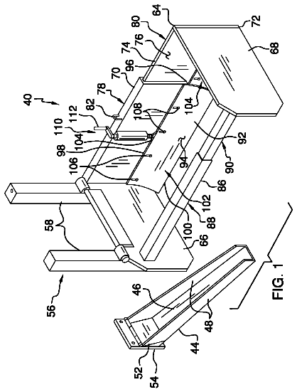
An aggregate spreading system includes a dump truck that has a cab and a bed.
US 9,797,115 B2 · Assignee: KOMATSU LTD. · Inventors: Kishimoto; Yasuki et al.
Sheet 1 of 10 from the published document. All sheets in the USPTO PDF
A power transmission device includes an input shaft, an output shaft, a gear mechanism, an energy-generating motor, a first clutch, and a locking device. The energy storage unit is configured to store the energy generated by the energy-generating motor. The gear mechanism includes a planetary gear mechanism, which includes a first rotation element, a second rotation element, and a third rotation element, which are mutually different. The first clutch is provided in the power transmission route between the engine and the first rotation element. The locking device locks or releases the second rotation element. The energy-generating motor is connected to the third rotation element. A controller locks the second rotation element, converges the rotation speeds of two rotation shafts in the first clutch to cause the first clutch to engage, and rotates the energy-generating motor using drive power from the engine to thereby accumulate energy in the energy storage unit.
1 of 10 drawing sheets so far from the published document, cropped to the drawing. Every sheet is in the USPTO PDF.
What the patent claimed, word for word. All of it is now free to use.
This application is a U.S. National stage application of International Application No. PCT/JP2015/0051396, filed on Jan. 20, 2015. This U.S. National stage application claims priority under 35 U.S.C. §119(a) to Japanese Patent Application No. 2014-015942, filed in Japan on Jan. 30, 2014, the entire contents of which are hereby incorporated herein by reference. BACKGROUND Field of the Invention
The present invention relates to a work vehicle and a work vehicle control method for charging. Background Information
Work vehicles, such as wheel loaders, are known that are equipped with a power transmission device that includes a torque converter and a multi-speed transmission (hereafter referred to as a “torque converter transmission”). Recently, on the other hand, the hydraulic mechanical transmission (HMT) and the electro-mechanical transmission (EMT) have been replacing torque converter transmissions as power transmission devices.
As disclosed in Japanese Laid-Open Patent Application Publication No. 2006-329244, an HMT includes a gear mechanism and a motor connected to the rotational elements in the gear mechanism, where a portion of the drive power from the engine is converted to hydraulic pressure and transmitted to the travel apparatus while the remainder of the drive power is mechanically transmitted to the travel apparatus.
An EMT is provided with a planetary gear mechanism and an electric motor, for instance, to allow for continuously variable shifting. One of three elements, i.e., the sun gear, the carrier, or the ring gear in the planetary gear mechanism, is connected to an input shaft, and a second element is connected to an output shaft. Additionally, a third element is connected to the electric motor. The electric motor functions as either a motor or a generator depending on the travel status of the work vehicle. In an EMT, the rotation speed of the output shaft varies continuously in accordance with the variation in the speed of the electric motor.
The HMT uses a hydraulic motor in place of the electric motor in the EMT. The hydraulic motor functions as either a motor or a pump depending on the travel status of the work vehicle. Similar to the EMT, the rotation speed ratio of the output shaft to the input shaft varies continuously in accordance with the variation in the rotation speed ratio of the hydraulic motor.
A hybrid vehicle equipped with a power transmission device provided with the above-described EMT or HMT is a series hybrid, a parallel hybrid, or a split power transmission based on the positional relationship between the engine, the motor-generator, the planetary gear mechanism, and the output shaft. Additionally, a split power transmission may be an input split, an output split, or a compound split type. An input-split power transmission device is provided with a single planetary gear mechanism located near the input shaft of the gear shifting device (near the output shaft of the engine). An output-split power transmission device is provided with a single planetary gear mechanism located near the output shaft of the gear shifting device (near the axle). A compound-split power transmission device is provided with two or more planetary gear mechanisms located near the input shaft and near the output shaft of the gear shifting device.
A battery or a capacitor is installed in a vehicle provided with an EMT for driving the electric motor. Thus, when the vehicle is in standby in a neutral or in a key-off state (i.e., where the engine stops because a key is turned to an off position), the amount of power in the battery or the capacitor will be less than the normal charge due to the effects of natural electric discharge. If an operation lever is switched to either the F-position or the R-position while there is less charge and the vehicle is started, the vehicle causes the motor to operate as a generator in accordance with the driving of the engine to return the battery or capacitor to its normal charge. As a result, the acceleration of the vehicle suffers because the driving of the engine is being used to charge the battery or capacitor during acceleration. Therefore, it is preferable to charge the battery or capacitor as appropriate if there is less charge even if it is during a stop or a neutral state where acceleration is not needed. Series hybrid and parallel hybrid output split vehicles can connect the output shaft of the engine to the rotation shaft of the motor-generator without going through the planetary gear mechanism; therefore, the generator may be operated via rotation of the engine to facilitate charging the battery and the like in the hybrid vehicle. However, given that the input split type and the compound split type transmissions connect the output shaft of the engine and the motor-generator via the planetary gear mechanisms, the desired kind of charging cannot be performed without modifying a portion of the rotation elements in the planetary gear mechanisms. Accordingly, charging a vehicle with an input split or compound split type transmission while the vehicle is stopped or in the neutral state tends to be more difficult compared to other transmission types.
The present invention proposes a work vehicle capable of charging and a work vehicle control method for charging which is applicable even to work vehicles equipped with a power transmission device configured to connect the output shaft of an engine to the rotation shaft of a motor-generator via a planetary gear mechanism.
A work vehicle according to a first exemplary embodiment of the present invention is provided with an engine, a hydraulic pump, a work implement, a travel apparatus, a power transmission device, a controller, and an energy storage unit. The hydraulic pump is driven by the engine; the work implement is driven by hydraulic fluid discharged from the hydraulic pump. The engine drives the travel apparatus. The power transmission device transmits the drive power from the engine to the travel apparatus. A power transmission device includes an input shaft, an output shaft, a gear mechanism, an energy-generating motor, a first clutch, and a locking device. The gear mechanism includes a planetary gear mechanism, and is configured to transmit the rotations of the input shaft to the output shaft. The planetary gear mechanism includes a first rotation element, a second rotation element, and a third rotation element, which are mutually different. The first clutch is provided in the power transmission route between the engine and the first rotation element. The locking device is configured to lock or release the second rotation element. The energy-generating motor is connected to the third rotation element. The power transmission device is configured such that changing the speed of the energy-generating motor changes the speed ratio of the output shaft relative to the input shaft in the power transmission device. The energy storage unit is configured to store the energy generated by the energy-generating motor. The controller is configured to control the power transmission device. The controller includes a speed adjustment unit configured to adjust the speed of the two rotation shafts in the first clutch. The controller locks the second rotation element using the locking device, converges the rotation speeds of two rotation shafts in the first clutch using the speed adjustment unit to cause the first clutch to engage, and rotates the energy-generating motor using the drive power from the engine to thereby accumulate energy in the energy storage unit.
The speed adjustment unit may be configured to cause the first clutch to engage while slipping the first clutch to allow the speeds of the two rotation shafts in the first clutch to converge when the energy stored in the energy storage unit is less than or equal to a first predetermined amount.
One of the rotation shafts in the first clutch may be a clutch input shaft connected to the output shaft of the engine; the other rotation shaft in the first clutch may be a clutch output shaft connected to the output shaft of the energy-generating motor via the second rotation element in the planetary gear mechanism, and the speed adjustment unit may be configured to control the motor so that the speed of the clutch output shaft converges with the speed of the clutch input shaft when the energy stored in the energy storage unit is greater than a first predetermined amount.
The locking device may include a parking brake configured to stop the output shaft. Further, the controller may be configured to engage the parking brake thereby locking the second rotation element when the energy stored in the energy storage unit is less than or equal to a second predetermined amount.
The locking device may include a connected motor that is connected to the second rotation element. Further, the controller may be configured to control the connected motor so that the speed of the connected motor becomes zero, thereby locking the second rotation element when the energy stored in the energy storage unit is greater than a second predetermined amount.
The controller may be configured to drive the energy-generating motor with the energy stored in the energy storage unit so that the energy-generating motor generates a torque in a direction that hinders rotation thereof due to the drive power from the engine when accumulating energy in the energy storage unit, when the energy stored in the energy storage unit is greater than a third predetermined amount.
The energy storage unit may be a capacitor.
The controller may be configured to increase the speed of the engine after the first clutch is engaged.
A method of controlling a work vehicle according to a second exemplary embodiment of the invention is a method of controlling a below described work vehicle. The work vehicle is provided with an engine, a hydraulic pump, a work implement, a travel apparatus, a power transmission device, a controller, and an energy storage unit. The hydraulic pump is driven by the engine. The work implement is driven by hydraulic fluid discharged from the hydraulic pump. The engine drives the travel apparatus. The power transmission device transmits the drive power from the engine to the travel apparatus. A power transmission device includes an input shaft, an output shaft, a gear mechanism, an energy-generating motor, a first clutch, and a locking device. The gear mechanism includes a planetary gear mechanism, and is configured to transmit the rotations of the input shaft to the output shaft. The planetary gear mechanism includes a first rotation element, a second rotation element, and a third rotation element, which are mutually different. The first clutch is provided on the power transmission route between the engine and the first rotation element. The locking device is configured to lock or release the second rotation element. The energy-generating motor is connected to the third rotation element. The power transmission device is configured such that changing the speed of the energy-generating motor changes the speed ratio of the output shaft relative to the input shaft in the power transmission device. The energy storage unit is configured to store the energy generated by the energy-generating motor. The control method includes a step of locking the second rotation element using the locking device, a step of converging the rotation speeds of two rotation shafts in the first clutch to cause the first clutch to engage, and a step of rotating the energy-generating motor using the drive power from the engine to thereby accumulate energy in the energy storage unit.
A work vehicle and a work vehicle control method according to exemplary embodiments of the present invention locks a second rotation element in a planetary gear mechanism, converges the rotation speeds of two rotation shafts in a first clutch to cause the first clutch to engage, and causes an energy-generating motor rotates using the drive power from the engine to thereby accumulate energy in an energy storage unit. Hereby, a work vehicle capable of charging and a work vehicle control method for charging are provided that are applicable even to work vehicles provided with a power transmission device configured to connect the output shaft of an engine and the rotation shaft of a motor-generator via a planetary gear mechanism.
FIG. 1 is a side view of a work vehicle.
FIG. 2 is a schematic view illustrating a configuration of the work vehicle.
FIG. 3 is a schematic view illustrating a configuration of a power transmission device according to a first exemplary embodiment.
FIG. 4 illustrates a detailed internal configuration for an inverter.
FIG. 5A is a flowchart outlining operations in the power transmission device according to the first exemplary embodiment.
FIG. 5B is a flowchart outlining operations in the power transmission device according to the first exemplary embodiment.
FIG. 5C is a flowchart outlining operations in the power transmission device according to the first exemplary embodiment.
FIG. 6 is a flowchart detailing operations of the inverter when charging the capacitor.
FIG. 7 is a schematic view illustrating a configuration of a power transmission device according to a second exemplary embodiment.
FIG. 8 is a flowchart outlining operations in the power transmission device according to a second exemplary embodiment. DESCRIPTION OF EXEMPLARY EMBODIMENTS First Exemplary Embodiment
Exemplary embodiments of the present invention are described below with reference to the drawings. A side view of a work vehicle 1 according to an exemplary embodiment of the present invention is illustrated in FIG. 1 . As illustrated in FIG. 1 , the work vehicle 1 is provided with a vehicle frame 2 , a work implement 3 , running wheels 4 , 5 , and a cab 6 . The work vehicle 1 is a wheel loader, and travels by rotationally driving the running wheels 4 , 5 . The work vehicle 1 uses the work implement 3 to perform work such as excavation or digging.
The vehicle frame 2 includes a front frame 16 and a rear frame 17 . The front frame 16 and the rear frame 17 are attached to be able to turn relative to each other horizontally. The work implement 3 and the running wheels 4 are attached to the front frame 16 . The work implement 3 is driven by hydraulic fluid from a later-described work implement pump 23 (refer to FIG. 2 ). A boom 11 and a bucket 12 are provided on the work implement 3 . The boom 11 is mounted to the vehicle frame 2 . The work implement 3 is provided with a lift cylinder 13 , and a bucket cylinder 14 . The lift cylinder 13 and the bucket cylinder 14 are hydraulic cylinders. One end of the lift cylinder 13 is attached to the front frame 16 . The other end of the lift cylinder 13 is attached to the boom 11 . Hydraulic fluid from the work implement pump 23 extends and retracts the lift cylinder 13 to thereby rotate the boom 11 vertically. A bucket 12 is attached at the front end of the boom 11 . One end of the bucket cylinder 14 is attached to the vehicle frame 2 . The other end of the bucket cylinder 14 is attached to the bucket 12 via a bell crank 15 . Hydraulic fluid from the work implement pump 23 extends and retracts the bucket cylinder 14 to thereby rotate the bucket 12 vertically.
The cab 6 and the running wheels 5 are attached to the rear frame 17 . The cab 6 is mounted on the vehicle frame 2 . Arranged within the cab 6 are a seat whereon an operator may sit, an operation device (later described), and the like.
The work vehicle 1 includes a steering cylinder 18 . The steering cylinder 18 is attached to the front frame 16 and the rear frame 17 . The steering cylinder 18 is also a hydraulic cylinder. Hydraulic fluid from a later-described steering pump 28 extends and retracts the steering cylinder 18 to thereby change the travel direction of the work vehicle 1 to the left or the right.
FIG. 2 is a schematic view illustrating a configuration of the work vehicle 1 according to an exemplary embodiment. As illustrated in FIG. 2 , the work vehicle 1 is equipped with an engine 21 , a PTO 22 , a power transmission device 24 , a travel apparatus 25 , an operation device 26 , a controller 27 , and the like.
The engine 21 may be a diesel engine. Output of the engine 21 is controlled by adjusting the amount of fuel injected into a cylinder in the engine 21 . The amount of fuel may be adjusted via the controller 27 controlling a fuel injector 21 a installed in the engine 21 . The work vehicle 1 is provided with an engine-speed detector 31 . The engine-speed detector 31 detects the speed of the engine and sends the controller 27 a detection signal indicative of the engine speed.
The work vehicle 1 may include the work implement pump 23 , the steering pump 28 , and a transmission pump 29 . The work implement pump 23 , the steering pump 28 , and the transmission pump 29 are hydraulic pumps. The PTO 22 transmits a portion of the drive power from the engine 21 to the hydraulic pumps 23 , 28 , 29 . In other words, the PTO 22 distributes the drive power from the engine 21 to the hydraulic pumps 23 , 28 , 29 , and to the power transmission device 24 .
The work implement pump 23 is driven by drive power from the engine 21 . The hydraulic fluid discharged from the work implement pump 23 is supplied to the above-described lift cylinder 13 and the bucket cylinder 14 via a work implement control valve 41 . The work vehicle 1 is equipped with a work-implement-pump pressure detector 32 . The work-implement-pump pressure detector 32 detects the discharge pressure of the hydraulic fluid expelled from the work implement pump 23 (referred to as “work-implement pump pressure” below), and sends the controller 27 a detection signal indicative of the work-implement pump pressure.
The work implement pump 23 is a variable displacement hydraulic pump. Changing the tilt angle of the swashplate or the tilt axis in the work implement pump 23 changes the discharge capacity of the work implement pump 23 . The work implement pump 23 is connected to a first capacity control device 42 . The first capacity control device 42 changes the tilt angle in the work implement pump 23 under the control of the controller 27 . The controller 27 may thereby control the discharge capacity of the work implement pump 23 . For instance, the first capacity control device 42 may adjust the tilt angle in the work implement pump 23 to create a fixed pressure differential in front of and behind the work implement control valve 41 . The first capacity control device 42 may also change the tilt angle in the work implement pump 23 as desired in accordance with a command signal from the controller 27 . More specifically, the first capacity control device 42 includes a first and a second valve (not shown). When the above-described work implement control valve 41 changes the amount of hydraulic fluid being supplied to the work implement 3 , a pressure differential is generated between the discharge pressure from the work implement pump 23 and the pressure of the hydraulic fluid after passing through the work implement control valve 41 , depending on the change in the position of the work implement control valve 41 . The first valve, under control of the controller 27 adjust the tilt angle in the work implement pump 23 so that the pressure differential in front of and behind the work implement control valve 41 remains constant even when the load on the work implement 3 fluctuates. Additionally, the second valve under control of the controller 27 may further change the tilt angle in the work implement pump 23 . The work vehicle 1 is equipped with a first tilt-angle detector 33 . The first tilt-angle detector 33 detects the tilt angle in the work implement pump 23 and sends the controller 27 a detection signal representing the tilt angle.
The steering pump 28 is driven by drive power from the engine 21 . The hydraulic fluid discharged from the steering pump 28 is supplied to the above-described steering cylinder 18 via a steering control valve 43 . The work vehicle 1 is equipped with a steering pump pressure detector 35 . The steering pump pressure detector 35 detects the pressure of the hydraulic fluid discharged from the steering pump 28 (termed “steering pump pressure” below), and sends the controller 27 a detection signal indicative of the steering pump pressure.
The steering pump 28 is a variable displacement hydraulic pump. Changing the tilt angle of the swashplate or the tilt axis in the steering pump 28 changes the discharge capacity of the steering pump 28 . The steering pump 28 is connected to a second capacity control device 44 . The second capacity control device 44 changes the tilt angle in the steering pump 28 under the control of the controller 27 . The controller 27 may thereby control the discharge capacity of the steering pump 28 . The work implement 1 is equipped with a second tilt-angle detector 34 . The second tilt-angle detector 34 detects the tilt angle in the steering pump 28 and sends the controller 27 a detection signal representing the tilt angle.
The transmission pump 29 is driven by the drive power from the engine 21 . The transmission pump 29 is a fixed displacement hydraulic pump. The hydraulic fluid discharged from the transmission pump 29 is supplied to clutches CF, CR, CL, CH in the power transmission device 24 via later-described clutch control valves VF, VR, VL, VH. A transmission pump pressure detector 36 detects the pressure of the hydraulic fluid discharged from the transmission pump 29 (termed “transmission pump pressure” below), and sends the controller 27 a detection signal indicative of the transmission pump pressure.
The PTO 22 transmits a portion of the drive power from the engine 21 to the power transmission device 24 . The power transmission device 24 transmits the drive power from the engine 21 to the travel apparatus 25 . The power transmission device 24 converts and outputs the drive power from the engine 21 . The details on the configuration of the power transmission device 24 are described later.
The travel apparatus 25 includes an axle 45 and running wheels 4 , 5 . The engine 21 drives the travel apparatus 25 . The axle 45 transmits the drive power from the power transmission device 24 to the running wheels 4 , 5 . Hereby, the running wheels 4 , 5 rotate. The work vehicle 1 is provided with an output speed detector 37 and an input speed detector 38 . The output speed detector 37 detects the rotation speed of the output shaft 63 in the power transmission device 24 (referred to as “output speed” below). Given that the output speed corresponds to the vehicle speed, the output speed detector 37 detects the vehicle speed due to the travel apparatus 25 by detecting the output speed. The input speed detector 38 detects the rotation speed of the input shaft 61 in the power transmission device 24 (referred to as “input speed” below). The output speed detector 37 sends the controller 27 a detection signal indicative of the output speed. The input speed detector 38 sends the controller 27 a detection signal indicative of the input speed.
Note that, instead of an output speed detector 37 and then input speed detector 38 a rotation speed detector that detects the rotation speed of rotation components inside the power transmission device 24 may be separately provided to send signals to the controller 27 , and the controller 27 may then compute the input speed and the output speed from the rotation speed of the rotation components.
The operator manipulates the operation device 26 . The operation device 26 may include a braking device 50 , and acceleration device 51 , a work implement operating device 52 , a forward-reverse switching device 54 , and a steering device 57 . Note that the operation device 26 may further include a gear shifting device 53 .
The acceleration device 51 includes an accelerator control 51 a , and an acceleration detector 51 b . The accelerator control 51 a is operated to establish a target speed for the engine 21 . The acceleration detector 51 b detects the degree to which the acceleration device 51 is operated (termed “accelerator operation amount” below). The acceleration detector 51 b sends the controller 27 a detection signal indicative of the accelerator operation amount.
The work implement operating device 52 contains a work implement control 52 a and a work implement operation detector 52 b . The work implement control 52 a is operated to move the work implement 3 . The work implement operation detector 52 b detects the position of the work implement control 52 a . The work implement operation detector 52 b outputs a detection signal indicative of the position of the work implement control 52 a to the controller 27 .
The gear shifting device 53 includes a gear-shift control 53 a , and a gear-shift detector 53 b . The operator may manipulate the gear-shift control 53 a to select a gear shifting pattern for the power transmission device 24 . The gear-shift detector 53 b detects the position of the gear-shift control 53 a . The gear-shift detector 53 b outputs a detection signal to the controller 27 indicative of the position of the gear-shift control 53 a.
A forward-reverse switching device 54 contains a forward-reverse switching control 54 a and a forward-reverse switch detector 54 b . In the discussion that follows, the forward-reverse switching device 54 , the forward-reverse switching control 54 a , and the forward-reverse switch detector 54 b are referred to as the FR operation device 54 , the FR control 54 a , and the FR switch detector 54 b respectively. The FR operation device 54 may be selectively switched to a forward-travel position (F), a neutral position (N), and a reverse-travel position (R). The FR switch detector 54 b detects the position of the FR control 54 a . The FR switch detector 54 b outputs a detection signal to the controller 27 indicative of the position of the FR control 54 a.
The steering device 57 includes a steering control 57 a . A pilot pressure is supplied to the steering control valve 43 based on the operation of the steering control 57 a allowing the steering device 57 to thereby actuate the steering control valve 43 . The operator may manipulate the steering control 57 a to change the travel direction of the work vehicle 1 to the left or the right. Note that the steering device 57 may convert the operation of the steering control 57 a into an electrical signal to actuate the steering control valve 43 .
The braking device 50 includes a brake control 50 a , and a braking detector 50 b . The operator may manipulate the brake control 50 a to operate the braking device generate a braking force for the work vehicle 1 . The braking detector 50 b detects the position of the brake control 50 a . The braking detector 50 b outputs a detection signal to the controller 27 indicative of the position of the brake control 50 a . The brake control 50 a includes a parking brake operation control that actuates a parking brake PB (later described) when operated. The parking brake operation control may be, for instance, a braking switch, or a parking lever manipulable by the operator. A pilot pressure is supplied to a parking brake control valve VB based on the operation of the parking brake operation control allowing the parking brake PB to thereby actuate the parking brake control valve VB. Finally, an operation signal is sent to the controller 27 when the parking brake operation control is operated.
The controller 27 includes a computing device, such as a CPU, and memory, such as RAM and ROM, and carries out processes for controlling the work vehicle 1 . The controller 27 also includes a motor control unit 55 and a clutch control unit 58 for controlling the power transmission device 24 , a braking control unit 59 for actuating the braking device 50 , and a storage unit 56 . The details on the configuration of the power transmission device 24 are described later. The storage unit 56 stores programs and data for controlling the work vehicle 1 .
The controller 27 outputs a command signal to the fuel injector 21 a indicative of a commanded throttle value to obtain a target speed in the engine 21 corresponding to the accelerator operation amount. The controller 27 controls the work implement control valve 41 on the basis of a detection signal from the work implement operation detector 52 b and thereby controls the hydraulic pressure supplied to the hydraulic cylinders 13 , 14 . The hydraulic cylinders 13 , 14 thereby extend and retract, moving the work implement 3 .
The details on the configuration of the power transmission device 24 are described next. FIG. 3 is a schematic view illustrating a configuration of the power transmission device 24 . As illustrated in FIG. 3 , the power transmission device 24 is provided with an input shaft 61 , a gear mechanism 62 , the output shaft 63 , a first motor MG 1 , a second motor MG 2 , and a capacitor 64 . The rotation speed ratio of the input shaft 61 to the output shaft 63 changes in the power transmission device 24 in accordance with the change in the speed of the first motor MG 1 , or the second motor MG 2 . The input shaft 61 is connected to the above described PTO 22 . The rotations of the engine 21 are received by the input shaft 61 via the PTO 22 . That is, the input shaft 61 is connected to the output shaft of the engine. The gear mechanism 62 transmits the rotations of the input shaft, 61 to the output shaft 63 . The output shaft 63 , connected to the above-described travel apparatus 25 , transmits the rotations from the gear mechanism 62 to the travel apparatus 25 .
The gear mechanism 62 transmits the drive power from the engine 21 . When the speed of the first motor MG 1 or the second motor MG 2 changes in the gear mechanism 62 , the gear mechanism 62 changes the speed ratio of the output shaft 63 to the input shaft 61 . The gear mechanism 62 includes an FR switching mechanism 65 , and a gear shifting mechanism 66 .
The FR switching mechanism 65 includes an F-clutch CF, and R-clutch CR, and F-clutch output shaft 61 f , and R-clutch output shaft 61 r , a first F-clutch gear Gf 1 , a second F-clutch gear Gf 2 , a first R-clutch gear Gr 1 , a second R-clutch gear Gr 2 , and a third R-clutch gear Gr 3 . The F-clutch CF connects or disconnects the F-clutch output shaft 61 f and the input shaft 61 (F-clutch input shaft). The R-clutch CR connects or disconnects the R-clutch output shaft 61 r and the input shaft 61 (R-clutch input shaft). The first F-clutch gear Gf 1 is connected to the F-clutch output shaft 61 f . The first R-clutch gear Gr 1 is connected to the R-clutch output shaft 61 r . The second F-clutch gear Gf 2 is connected to the power transmission shaft 67 and engaged with the first F-clutch gear Gf 1 . The third R-clutch gear Gr 3 is connected to the power transmission shaft 67 and engaged with the second R-clutch gear Gr 2 . The second R-clutch gear Gr 2 is engaged with the first R-clutch gear Gr 1 and the third R-clutch gear Gr 3 . The second F-clutch gear Gf 2 and the third R-clutch gear Gr 3 are connected to the output shaft in the second motor MG 2 via the power transmission shaft 67 , first sun gear S 1 , first planetary gears P 1 , first ring gear R 1 , first outer ring gear Go 1 . That is, the F-clutch output shaft 61 f and the R-clutch output shaft 61 r are connected to the output shaft in the second motor MG 2 via at least one rotation element in the first planetary gear mechanism.
As illustrated in FIG. 3 , the first and second F-clutch gears Gf 1 , Gf 2 , and the first through third R-clutch gear Gr 1 -Gr 3 are merely examples, and may be any configuration so long as the rotation direction of the power transmission shaft 67 when the F-clutch CF is connected, and the rotation direction of the power transmission shaft 67 when the R-clutch CR is connected are mutually opposite.
The F-clutch CF and the R-clutch CR are hydraulic, with the transmission pump 29 supplying the hydraulic fluid to each of clutches CF, CR. An F-clutch control valve VF controls the hydraulic fluid supplied to the F-clutch CF. An R-clutch control valve VR controls the hydraulic fluid supplied to the R-clutch CR. The clutch control valves VF, VR are controlled via the command signals from the clutch control unit 58 . The F-clutch CF and the R-clutch CR may be switched on (engaged) or switched off (disengaged) which thereby switches the direction of rotation of the output from the FR switching mechanism 65 . That is, the F-clutch CF is connected to the gear mechanism 62 (more specifically, to the first F-clutch gear GM that orients the travel apparatus 25 to travel forward. Additionally the R-clutch CR is connected to the gear mechanism 62 (more specifically, to the first R-clutch gear Gr 1 ) that orients the travel apparatus 25 to travel in reverse.
The gear shifting mechanism 66 includes the power transmission shaft 67 , the first planetary gear mechanism 68 , the second planetary gear mechanism 69 , a hi-lo switching mechanism 70 , and an output gear 71 . The power transmission shaft 67 is connected to the FR switching mechanism 65 .
The first planetary gear mechanism 68 includes a first sun gear S 1 , a plurality of first planetary gears P 1 , a first carrier C 1 supporting the plurality of first planetary gears P 1 , and a first ring gear R 1 . The first sun gear S 1 is connected to the power transmission shaft 67 . For convenience, the rotation element in the first planetary gear mechanism 68 connected to the engine 21 via the FR switching mechanism 65 is referred to as the first rotation element. That is, the first sun gear S 1 corresponds to the first rotation element. The plurality of first planetary gears P 1 engages with the first sun gear S 1 and is supported on the first carrier C 1 to be able to rotate. A first carrier gear Gc 1 is provided on the periphery of the first carrier C 1 . The first ring gear R 1 is able to rotate while engaged with the plurality of first planetary gears P 1 . The first ring gear R 1 is also provided with a first outer ring gear Go 1 at the periphery thereof.
The second planetary gear mechanism 69 includes a second sun gear S 2 , a plurality of second planetary gears P 2 , a second carrier C 2 supporting the plurality of second planetary gears P 2 , and a second ring gear R 2 . The second sun gear S 2 is connected to the first carrier C 1 . The plurality of second planetary gears P 2 engages with the second sun gear S 2 and is supported on the second carrier C 2 to be able to rotate. The second ring gear R 2 is able to rotate while engaged with the plurality of second planetary gears P 2 . The second ring gear R 2 also is provided with a second outer ring gear Go 2 at the periphery thereof. The second outer ring gear Go 2 engages with the output gear 71 whereby the rotation of the second ring gear R 2 is output to the output shaft 63 via the output gear 71 . For convenience, the rotation element in the second planetary gear mechanism 69 connected directly to rotation element in the first planetary gear mechanism 68 on the carrier, bypassing the clutch, is referred to as the fourth rotation element. That is, the second sun gear S 2 corresponds to the fourth rotation element. Additionally, the rotation element in the second planetary gear mechanism 69 connected to the output shaft 63 is referred to as the sixth rotation element. That is, the second ring gear R 2 corresponds to the sixth rotation element.
The hi-lo switching mechanism 70 is used to selectively switch the drive power transmission route in the power transmission device 24 between a first mode and a second mode. In the first exemplary embodiment the first mode is a Lo mode that may be selected when the speed ratio is low, and the second mode is a Hi mode that may be selected when the speed ratio is high. The hi-lo switching mechanism 70 includes an H-clutch CH that is “on” during the Hi mode, and an L-clutch CL that is “on” during the Lo mode. The H-clutch CH connects or disconnects the first ring gear R 1 and the second carrier C 2 . Additionally, the L-clutch CL connects or disconnects the second carrier C 2 and a fixed end 72 , thereby prohibiting or permitting rotation of the second carrier C 2 . For convenience, the rotation element in the second planetary gear mechanism 69 connected to the L-clutch CL and the H-clutch CH is referred to as the fifth rotation element. Accordingly the second carrier C 2 corresponds to the fifth rotation element.
The H-clutch CH is configured so that the H-clutch CH can limit the movement of the second carrier C 2 (fifth rotation element) by connecting the first ring gear R 1 and the second carrier C 2 , or release any limitations on the movement of the second carrier C 2 (fifth rotation element) by disconnecting the first ring gear R 1 and the second carrier C 2 . The L-clutch CL is similarly configured so that the L-clutch CL stops (locks) the second carrier C 2 (fifth rotation element) or releases the second carrier C 2 (fifth rotation element). In other words, the L-clutch CL is configured so that the L-clutch CL can limit the movement of the second carrier C 2 (fifth rotation element) by connecting the second carrier C 2 and the fixed end 72 , or release any limitations on the movement of the second carrier C 2 (fifth rotation element) by disconnecting the second carrier C 2 from the fixed end 72 . Thus, in the first exemplary embodiment, a component configured to limit the movement of or release limitations on the movement of the fifth rotation element is referred to as a rotation-element locking means or locking device. According to this definition, the H-clutch CH and the L-clutch CL are rotation-element locking means or locking devices.
Note that since the second carrier C 2 is locked when the H-clutch CH is disconnected and the L-clutch CL is connected, the second planetary gear mechanism 69 operates identically to a so-called deceleration apparatus where the speed reduction ratio is locked. Therefore, the second planetary gear mechanism 69 cannot provide continuously variable shifting. Accordingly, the power transmission device 24 is in input split mode during the Lo mode. Whereas, since the first ring gear R 1 and the second carrier C 2 are connected when the L-clutch CL is disconnected and the H-clutch CH is connected, the first planetary gear mechanism 68 and the second planetary gear mechanism 69 can provide continuously variable shifting. Therefore, the power transmission device 24 is in compound split mode during Hi mode.
Note that the clutches CH, CL are hydraulic, with the transmission pump 29 supplying the hydraulic fluid thereto. An H-clutch control valve VH controls the hydraulic fluid bound for the H-clutch CH. An L-clutch CL control valve VL controls the hydraulic fluid bound for the L-clutch CL. The clutch control valves VH, VL are controlled via the command signals from the clutch control unit 58 .
The description continues in the full USPTO document.
About 6,829 words. The USPTO PDF has it with every drawing.
Fees are due 3.5, 7.5 and 11.5 years after grant. This patent expired on October 24, 2025, so the fee marked "not paid" was the one that went unpaid.
WORK VEHICLE, AND WORK VEHICLE CONTROL METHOD FOR CHARGING
Filed Jan 2015 · published Jun 2016Work vehicle, and work vehicle control method for charging
Filed Jan 2015 · granted Oct 2017Earlier publications, parents and continuations. None of them can still be enforced, or this patent would not be listed.
Prior art cited by the examiner or applicant. Useful when you check your own idea for novelty.
Everything on this page comes from the documents linked above.