Field of the invention
The invention relates to an energy supply system and control method for a lifting apparatus, and specifically to a cage energy supply system and control method thereof.
Background of the invention
Cage is the primary equipment for carriers in a mine well. The bottom of the cage is connected with a tail rope beam suspension device. In the recent years, With the increase in security awareness and the continuously improvement of the automation level of the mine, the interior of the cage is equipped with some low voltage power devices, such as illumination lamps, electric cage curtain doors, secure communication devices and the like. Such apparatuses have to be supported by the stable and reliable power source to normally operate. In the prior art, one storage battery is employed to supply power; after the battery runs out, it must be removed for charging and replaced with a fully charged storage battery, or it is charged by utilizing a charging system disposed at a wellhead. This not only wastes human power, but also has long charging time and is likely to delay the normal operation of the lifting apparatus.
Summary of the invention
In order to overcome the disadvantages in the prior art, the invention provides a cage energy supply system and control method thereof with stable and reliable system, high safety and high automation degree, which solves the problem of power consumption automation of the lifting cage in the mine well.
The technical solution to achieve the above-mentioned objective of the invention is that: the energy supply system comprises a tail rope beam suspension device connected to the bottom of a cage; the energy supply system further comprises wind power generation devices and a control device; wind power generation devices, the tail rope beam suspension device and a control device are all connected to the bottom of a cage box, the tail rope beam suspension device and the control device are located on the central axis of the bottom of the cage box, and the two sides of the tail rope beam suspension device are each connected with one wind power generation device.
The wind power generation device further comprises a pneumatic part, a power generation part and a power storage part; the pneumatic part comprises a blade, a hub, a bevel gear shaft, a rotor bearing, a bearing bracket and a fixed plate; the blade is connected to the bevel gear shaft through the hub; the bevel gear shaft is in a clearance fit with the rotor bearing bracket; the bearing bracket is connected to the fixed plate through a bolt; the fixed plate is riveted to the bottom of the cage.
A distance from a plane of rotation of the blade to the bottom of the cage box is a feature distance L, the distance range of the feature distance L is [0.6 m, 1.0 m].
The power generation part comprises a low-speed bevel gear shaft, a pedestal bearing, a low-speed coupling, a gearbox, a high-speed shaft, a high-speed coupling, an electric generator and a fixed case body; the gearbox comprises a pair of meshing gears; the gear of the low-speed bevel gear shaft is engaged with that of the bevel gear shaft of a wind machine part of the device; the low-speed bevel gear shaft is connected with a gearbox input shaft through the low-speed coupling; a gearbox output shaft is connected with the high-speed shaft through the high-speed coupling; the high-speed shaft is connected with an input shaft of a rotor winding of the electric generator through the high-speed coupling.
The power storage part comprises a storage battery that is connected with an external control system through charging and power supply interfaces.
The control device comprises an electric energy input interface in parallel, an input current sampling circuit, a current-to-voltage converter, a main controller, MOS switching circuits, a first storage battery charging interface, a first storage battery power supply interface, a second storage battery charging interface, a second storage battery power supply interface and a power supply output interface; the electric energy input interface in parallel is the one that inputs the electric energy to the storage battery after output electric energy lines of two wind driven generators are connected in parallel; an input end of the input current sampling circuit is connected with the storage battery charging interfaces and an output end is connected with an input end of the current-to-voltage converter; an output end of the current-to-voltage converter transmits a signal to the main controller; an output end of the main controller is connected with a grid of the MOS switching circuit; an MOS switching circuit (IA) is disposed between the electric energy input end in parallel and the first storage battery charging interface; an MOS switching circuit (IB) is disposed between the electric energy input end in parallel and the second storage battery charging interface; an MOS switching circuit (OA) is disposed between the first storage battery power supply interface and the power supply output interface; an MOS switching circuit (OB) is disposed between the second storage battery power supply interface and the power supply output interface; the power supply output interface is connected with an external voltage reducing and increasing apparatus to supply power for a cage illumination system and a driving motor of a power-driven cage curtain door.
The control method of the energy supply system is as follows:
when the wind power generation devices and the control system are in an operating state that the first storage battery is charged and the second storage battery supplies power, the MOS switching circuit (IA) is in a turn-on state, the MOS switching circuit (IB) is in a cutoff state, meanwhile, the MOS switching circuit (OB) is in a turn-on state, the MOS switching circuit (OA) is in a cutoff state; instead, the turn-on and cutoff states of each MOS switching circuit are opposite;
the input end of the current sampling circuit samples a charging current of the first storage battery at intervals of set value time t 1 ; the sampled current signal is converted into a voltage signal through the current-to-voltage converter and is transmitted to the main controller for analysis and judgment; the voltage signal is compared with a set value U that is a converted voltage value corresponding to a current value when the storage battery is saturated;
if the voltage value is less than the set value, the storage battery is saturated with charging, the main controller enters an interruption and carries out timekeeping to send signals to the MOS switching circuits such that the MOS switching circuit (OA) turns on, the MOS switching circuit (IB) turns on, the MOS switching circuit (IA) is cutoff, meanwhile, timekeeping is started, and the timekeeping is a certain set value time t 2 , in order not to affect the normal operation of the power device for the cage due to the conversion between turn-on and cutoff states of the MOS switching circuit; after reaching the timekeeping time, the main controller sends a signal to enable a cutoff of the MOS switching circuit (OB). Benefits: Since the above-mentioned solution is used, the wind power generation system at the bottom of a cage and control method thereof provided by the invention lie in that: the characteristics that the descending speed of the cage is high, and the relative wind speed of an auxiliary shaft is high are utilized; the requirement of the cage for supplying power to the power device is achieved in combination with the wind power generation principle, and meanwhile the power supply requirement of the control device is met; the device is simple in structure, safe and reliable, and only needs to be overhauled and maintained at regular intervals so as to achieve the automation requirement of the internal power supply for the lifting apparatus; two wind power generation devices charge one storage battery at the same time by the signal collection and judgment processing of the control device, the two storage batteries carry out alternative charging and power supply, so that a power device for the cage is supported by the stable and reliable power source all the time, thereby completely solving the problem of the power consumption automation of the lifting cage in the mine well. The advantages of the invention are that: the wind power generation device mounted at the bottom of the cage is capable of realizing power generation by itself and charging the storage battery; the control device is capable of realizing the automatic switching between charging and power supply of the storage battery, and the system is stable, reliable and high in safety and automation degree.
Description of the drawings
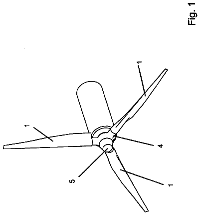
FIG. 1 is a structural schematic diagram of a wind power generation device at the bottom of a cage of the invention.
FIG. 2 is a schematic diagram of the arrangement of each device at the bottom of a cage of the invention.
FIG. 3 is a schematic diagram of a control principle of a control device of the invention.
FIG. 4 is a control flow diagram of a control device of the invention.
In the drawings, 1 , a blade; 2 , a hub; 3 , a rotor bearing; 4 , a bevel gear shaft; 5 , a bearing bracket; 6 , a fixed plate; 7 , the bottom of a cage box; 8 , a low-speed bevel gear shaft; 9 , a pedestal bearing; 10 , a low-speed coupling; 11 , a gearbox; 12 , a high-speed coupling; 13 , a high-speed shaft; 14 , an electric generator; 15 , a fixed case body; 16 , a first storage battery; 17 , a second storage battery; 18 , a tail rope beam suspension device; 19 , a control device.
Detailed description of the embodiments
One embodiment of the invention is further described in connection with the accompanying drawings:
The energy supply system of the invention comprises a tail rope beam suspension device connected to the bottom of a cage; the energy supply system further comprises wind power generation devices and a control device; the wind power generation devices, the tail rope beam suspension device and the control device are all connected to the bottom of a cage box, the tail rope beam suspension device and the control device are located on the central axis of the bottom of the cage box, and two sides of the tail rope beam suspension device are each connected with one wind power generation device.
The wind power generation device further comprises a pneumatic part, a power generation part and a power storage part; the pneumatic part comprises a blade, a hub, a bevel gear shaft, a rotor bearing, a bearing bracket and a fixed plate; the blade is connected to the bevel gear shaft through the hub; the bevel gear shaft is in a clearance fit with the rotor bearing bracket; the bearing bracket is connected to the fixed plate through a bolt; the fixed plate is riveted to the bottom of the cage.
A distance from a plane of rotation of the blade to the bottom of the cage box is a feature distance L, the distance range of the feature distance L is [0.6 m, 1.0 m].
The power generation part comprises a low-speed bevel gear shaft, a pedestal bearing, a low-speed coupling, a gearbox, a high-speed shaft, a high-speed coupling, an electric generator and a fixed case body; the gearbox comprises a pair of meshing gears; the gear of the low-speed bevel gear shaft is engaged with that of the bevel gear shaft of a wind machine part of the device; the low-speed bevel gear shaft is connected with a gearbox input shaft through the low-speed coupling; a gearbox output shaft is connected with the high-speed shaft through the high-speed coupling; the high-speed shaft is connected with an input shaft of a rotor winding of the electric generator through the high-speed coupling.
The power storage part comprises a storage battery that is connected with an external control device through charging and power supply interfaces.
The control device comprises an electric energy input interface in parallel, an input current sampling circuit, a current-to-voltage converter, a main controller, MOS switching circuits, a first storage battery charging interface, a first storage battery power supply interface, a second storage battery charging interface, a second storage battery power supply interface and a power supply output interface; the electric energy input interface in parallel is the one that inputs the electric energy to the storage battery after output electric energy lines of two wind driven generators are connected in parallel; an input end of the input current sampling circuit is connected with the storage battery charging interfaces and an output end is connected with an input end of the current-to-voltage converter; an output end of the current-to-voltage converter transmits a signal to the main controller; an output end of the main controller is connected with a grid of the MOS switching circuit; an MOS switching circuit (IA) is disposed between the electric energy input end in parallel and the first storage battery charging interface; an MOS switching circuit (IB) is disposed between the electric energy input end in parallel and the second storage battery charging interface; an MOS switching circuit (OA) is disposed between the first storage battery power supply interface and the power supply output interface; an MOS switching circuit (OB) is disposed between the second storage battery power supply interface and the power supply output interface; the power supply output interface is connected with an external voltage reducing and increasing apparatus to supply power for a cage illumination system and a driving motor of a power-driven cage curtain door.
The control method of the energy supply system is as follows:
when the wind power generation devices and the control system are in an operating state that the first storage battery is charged and the second storage battery supplies power, the MOS switching circuit (IA) is in a turn-on state, the MOS switching circuit (IB) is in a cutoff state, meanwhile, the MOS switching circuit (OB) is in a turn-on state, the MOS switching circuit (OA) is in a cutoff state; instead, the turn-on and cutoff states of each MOS switching circuit are opposite;
the input end of the current sampling circuit samples a charging current of the first storage battery at regular intervals which are set values t 1 depending on the actual lifting condition; the sampled current signal is converted into a voltage signal through the current-to-voltage converter and is transmitted to the main controller for analysis and judgment; the voltage signal is compared with a set value U that is a converted voltage value corresponding to a current value when the storage battery is saturated;
if the voltage value is less than the set value, the storage battery is saturated with charging, the main controller enters an interruption and carries out timekeeping to send signals to the MOS switching circuits such that the MOS switching circuit (OA) turns on, the MOS switching circuit (IB) turns on, the MOS switching circuit (IA) is cutoff, meanwhile timekeeping is started, and the timekeeping is a certain set time value t 2 , in order not to affect the normal operation of the power device for the cage due to the conversion between turn-on and cutoff states of the MOS switching circuit; after reaching the timekeeping time, the main controller sends a signal to enable a cutoff of the MOS switching circuit (OB).
Embodiment: referring to FIGS. 1 and 2 , the wind power generation device at the bottom of the cage of the invention is integrally fixed to the bottom 7 of a cage box in structure; left and right sides thereof are symmetric relative to a tail rope beam suspension device 18 ; a pair of cages of the auxiliary shaft in the mine well are driven by a lifting mechanism to ascend and descend respectively; when the cage descends, it is quickly accelerated to a stable speed, i.e., a rated wind speed of a wind driven generator; a blade 1 is a twisted blade; the installation angles at the blade wings are different; an installation angle at the radius r.sub.i along the wingspan direction is θ.sub.i; the blade rotating directions of two wind driven generators are opposite under the action of the wind force to maintain the reliability and stability of the cage device; at the same time, a distance from the blade 1 to the bottom 7 of the cage box is a feature distance L which ensures that a sufficient fluid space can be formed between upper and lower ends of the blade. The blade 1 drives a bevel gear shaft 4 to rotate through a hub 2 ; the bevel gear shaft 4 is fixed below the bottom 7 of the cage box in a vertical direction through a rotor bearing 3 , a bearing bracket 5 and a fixed plate 6 .
A plane of rotation of the blade 1 to the bottom 7 of cage box is a feature distance L, the distance range of the feature distance L is [0.6 m, 1.0 m].
A low-speed bevel gear shaft 8 is engaged with the bevel gear shaft 4 for rotation. The other end of the low-speed bevel gear shaft 8 is connected with an input shaft of a gearbox 11 through a low-speed coupling 10 ; the meshing gears in the gearbox 11 act to increase the rotating speed; an output shaft of the gearbox 11 is connected with a high-speed shaft 13 through a high-speed coupling 12 ; the other end of the high-speed shaft 13 is connected with an input shaft of an electric generator through the high-speed coupling 12 to drive a rotor winding to rotate, thereby creating an inductive electromotive force and outputting electric energy.
Referring to FIGS. 2, 3 and 4 , a control device 19 is installed below the bottom 7 of cage box at a front end (or tail end) of the tail rope beam suspension device 18 in the middle position and is in the same central axis as the tail rope beam suspension device 18 .
During the normal charging and power supply process, if a first storage battery is in a charging state and an MOS switching circuit (IA) turns on, a second storage battery is in a power supply state, which is to say, an MOS switching circuit (OB) turns on, an MOS switching circuit (OA) is cutoff, and an MOS switching circuit (IB) is cutoff. A current sampling module samples a charging current of the first storage battery at intervals of set value time t 1 , passes through a current-to-voltage converter, a voltage signal is transmitted to a main controller; the main controller carries out comparison and analysis with the set value; when the voltage signal is less than the set value, it is indicated that the first storage battery is saturated with charging; the main controller sends a signal to enable the turn-on of the MOS switching circuit (OA), the cutoff of the MOS switching circuit (IA), the turn-on of the MOS switching circuit (IB) and it begins timekeeping; when the timekeeping reaches the set value, the main controller sends a signal to enable the MOS switching circuit (OB) to be cutoff; the switching among all of the charging and power supply functions is completed and it circulates sequentially.
 Lapsed, fee not paid7 drawings