 Lapsed, fee not paid7 drawings
Vehicles & Drones · US 9,796,214 B2
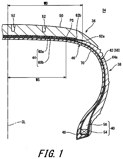
Pneumatic tire
To provide a pneumatic tire 34 in which weight reduction is achieved without deteriorating internal pressure maintaining performance.
US 9,796,244 B2 · Assignee: HONDA MOTOR CO., LTD. · Inventors: Cook; Michael D et al.
Sheet 1 of 5 from the published document. All sheets in the USPTO PDF
A thermal management system and method for a vehicle can include providing an engine, a transmission, a radiator, and a thermostat. A first heat exchanger can be in fluid communication with the transmission to heat or cool transmission fluid. A hot branch line can extend from the engine to the first heat exchanger to supply engine coolant to the first heat exchanger. The hot branch line can be in fluid communication with each of the engine and the first heat exchanger. A heat exchanger return line can be in fluid communication with each of the first heat exchanger and an inlet of the thermostat.
1 of 5 drawing sheets so far from the published document, cropped to the drawing. Every sheet is in the USPTO PDF.
What the patent claimed, word for word. All of it is now free to use.
BACKGROUND Description of the Related Art
The exhaust gas emissions of an internal combustion engine and the operating efficiency of powertrain components such as an internal combustion engine and a multiple speed ratio transmission are a function of the operating temperature of mechanical parts of the respective powertrain component and the operating temperature of the fluid(s) flowing through the respective powertrain component. At relatively low operating temperatures, the viscosity of lubricant in the engine and the transmission is relatively high and the reaction efficiency of the catalytic converter is relatively low. Thus, the operating efficiencies of the engine and the transmission are relatively low. Further, during a cold-start condition in cold weather, the warm-up rate of the passenger compartment can be relatively low. By contrast, under heavy load conditions, the components of the engine and/or the transmission can be subject to excessive thermal exposure. Thus, the operating efficiencies of the engine and the transmission can be reduced below an optimum value due to thermal stress, improper viscosity values, as well as other variables related to excessive thermal exposure.
Thus, there is a need to provide a thermal management system that can efficiently regulate the flow and temperature of fluids (such as, but not limited to, engine coolant, engine oil, engine exhaust gas, transmission lubricating oil, and transmission hydraulic fluid) in the powertrain in order to minimize powertrain warm-up, maximize heat available for warming the passenger compartment and/or maintaining the powertrain fluids at optimum operating temperatures during all powertrain loads.
According to one aspect of the disclosure a thermal management system for a vehicle having an engine and a transmission, the system can include a radiator configured for fluid communication with the engine, a thermostat including an inlet, an outlet, and a valve structure, the inlet being in fluid communication with the radiator, the outlet being configured for fluid communication with the engine, and the valve structure movable between a first position and a second position such that when the valve is in the first position the valve substantially prevents fluid communication between the inlet and the outlet, and when the valve is in the second position the inlet is in fluid communication with the outlet, a first heat exchanger in fluid communication with the transmission, a hot branch line extending from the engine to the first heat exchanger and in fluid communication with each of the engine and the first heat exchanger, and a heat exchanger return line in fluid communication with each of the first heat exchanger and the inlet of the thermostat.
According to another aspect of the disclosed subject matter, the thermal management system can include a heater core in ambient fluid communication with a passenger compartment of the vehicle, the heater core being in separate fluid communication with the engine and the outlet of the thermostat such that fluid from the heater core returns directly to the engine and fluid from the engine flows to the heater core along a first circuit, and fluid from the engine flows to the first heat exchanger along a second circuit, and the first circuit and second circuit are parallel circuits with respect to each other.
According to another aspect of the disclosed subject matter, the thermal management system can include a heater core in ambient fluid communication with a passenger compartment of the vehicle, a first fluid circuit and a second fluid circuit. The first fluid circuit can be in fluid communication with the engine and the heater core such that fluid flows from the engine to the heater core, then flows through the heater core, and then flows from the heater core to the outlet of the thermostat. The second fluid circuit can be in fluid communication with the engine and the first heat exchanger such that fluid flows from the engine to the first heat exchanger, then flows through the first heat exchanger, and then flows to the inlet of the thermostat.
According to another aspect of the disclosed subject matter, the system can include a second heat exchanger, a valve in fluid communication with the first heat exchanger, the second heat exchanger and the transmission and configured to selectively operate in a first mode and selectively operate in a second mode, wherein when in the first mode, fluid from the first heat exchanger bypasses the second heat exchanger and flows to the transmission, and when in the second mode, fluid from the first heat exchanger flows through the second heat exchanger and then flows to the transmission.
According to another aspect of the disclosed subject matter, the system can include a heater core in fluid communication with the engine, an exhaust pipe in fluid communication with the engine, and a second heat exchanger in fluid communication with the exhaust pipe and the heater core.
According to another aspect of the disclosed subject matter, a thermal management system for a vehicle can include an engine, a transmission, an exhaust pipe in fluid communication with the engine, an exhaust gas heat exchanger in fluid communication with the exhaust pipe, a transmission fluid cooler, and a valve in fluid communication with the transmission, the exhaust gas heat exchanger and the transmission fluid cooler and configured to selectively operate in a first mode and selectively operate in a second mode, wherein when in the first mode, fluid from the transmission flows through one of the exhaust gas heat exchanger and the transmission fluid cooler and bypasses the other of the exhaust gas heat exchanger and the transmission fluid cooler, and when in the second mode, fluid from the transmission flows through at least the other of the exhaust gas heat exchanger and the transmission fluid cooler.
According to another aspect of the disclosed subject matter, a vehicle can include an engine, a transmission, and a thermal management system including: a radiator configured for fluid communication with the engine, a thermostat including an inlet, an outlet, and a valve structure, the inlet being in fluid communication with the radiator, the outlet being configured for fluid communication with the engine, and the valve structure movable between a first position and a second position such that when the valve is in the first position the valve substantially prevents fluid communication between the inlet and the outlet, and when the valve is in the second position the inlet is in fluid communication with the outlet, a first heat exchanger in fluid communication with the transmission, a hot branch line extending from the engine to the first heat exchanger and in fluid communication with each of the engine and the first heat exchanger, and a heat exchanger return line in fluid communication with each of the first heat exchanger and the inlet of the thermostat.
According to another aspect of the disclosed subject matter, a method for directing fluid through a vehicle thermal management system can include providing an engine including engine fluid configured to flow through the engine, providing a radiator in fluid communication with the engine, providing a thermostat including an inlet in fluid communication with the radiator and an outlet in fluid communication with the engine, providing a transmission connected to the engine, providing a first heat exchanger in fluid communication with the transmission and in separate fluid communication with the engine and the inlet of the thermostat, circulating the engine fluid through the engine radiator, the engine, and the first heat exchanger, causing the engine fluid exiting the first heat exchanger to directly enter the inlet of the thermostat, and circulating transmission fluid through the transmission and the first heat exchanger.
The disclosed subject matter of the present application will now be described in more detail with reference to exemplary embodiments of the apparatus and method, given by way of example, and with reference to the accompanying drawings, in which:
FIG. 1 is a schematic view of an exemplary embodiment of a vehicle including a thermal management system made in accordance with principles of the disclosed subject matter.
FIG. 2 is a schematic view of a first embodiment of a thermal management system for a vehicle made in accordance with principles of the disclosed subject matter.
FIG. 3 is a schematic view of a second embodiment of a thermal management system for a vehicle made in accordance with principles of the disclosed subject matter.
FIG. 4 is a schematic view of a third embodiment of a thermal management system for a vehicle made in accordance with principles of the disclosed subject matter.
FIG. 5 is a schematic view of a fourth embodiment of a thermal management system for a vehicle made in accordance with principles of the disclosed subject matter.
FIG. 6 is a schematic view of a fifth embodiment of a thermal management for system a vehicle made in accordance with principles of the disclosed subject matter.
FIG. 7 is a schematic view of a sixth embodiment of a thermal management system for a vehicle made in accordance with principles of the disclosed subject matter.
FIG. 8 is a schematic view of a seventh embodiment of a thermal management system for a vehicle made in accordance with principles of the disclosed subject matter.
FIG. 9 is a schematic view of an eighth embodiment of a thermal management system for a vehicle made in accordance with principles of the disclosed subject matter.
FIG. 10 is a schematic view of a ninth embodiment of a thermal management system for a vehicle made in accordance with principles of the disclosed subject matter.
FIG. 1 schematically illustrates a vehicle 10 that can include an exemplary thermal management system 12 made in accordance with principles of the disclosed subject matter. The vehicle 10 can include an internal combustion engine 14 , a transmission 16 , a pair front wheels 18 L,R, a pair of rear wheels 20 L,R, and a body 22 . The body 22 can include a passenger compartment 24 (indicated schematically by a dashed line).
The system 12 can control fluid communication (indicated by the double headed arrows) between the internal combustion engine 14 , the transmission 16 , the passenger compartment 24 , and the ambient environment in order to regulate the heat transfer amongst the engine 14 , the transmission 16 , and the passenger compartment 24 . The thermal management system 12 can improve fuel efficiency of the vehicle 10 , minimize emissions resulting from combustion in the engine 14 , enhance responsiveness of the climate control for the passenger compartment 24 , and/or minimize the thermal effects on the engine 14 and/or the transmission 16 .
FIG. 2 illustrates a first exemplary embodiment of a thermal management system 112 in accordance with the principles of the disclosed subject matter. The fluids acted upon by the system 112 can be engine fluid (such as but not limited to water, ethylene glycol, a combination of water and ethylene glycol, and exhaust gas), transmission fluid (such as, but not limited to, lubricating oil and hydraulic oil (also known as automatic transmission fluid or ATF)), ambient air, and air inside the passenger compartment.
This exemplary first embodiment of the thermal management system 112 can include a radiator 114 , a reservoir 116 , a heater core 118 , a first heat exchanger 122 , a thermostat 124 , a control valve 126 , and a plurality of conduits 128 , 130 , 132 , 134 , 136 , 138 , 140 , 142 , 144 , 146 , 148 .
FIG. 2 also schematically illustrates further exemplary details of the engine 14 . The engine 14 can include one or more combustion cylinders 26 that can be arranged along a straight line, in a V-shape, in a W-shape, or horizontally opposed. In the exemplary embodiment of FIG. 2 , the engine 14 can include a plurality of cylinders 26 arranged in a first bank 28 and a second bank 30 . The first and second banks 28 , 30 can be arranged in a V-shape or the banks 28 , 30 can be horizontally opposed. Each cylinder 26 can include at least one exhaust valve 32 that can be configured to selectively connect the respective cylinder 26 for fluid communication with the ambient environment via an exhaust system, as will be described in further detail below.
The thermal management system 112 can include a water jacket formed in the engine 14 . In the exemplary embodiment schematically represented in FIG. 2 , the water jacket can include an inlet portion 34 and two bank portions 36 , 38 . The inlet portion 34 can be in fluid communication with an outlet 152 of the thermostat 124 . Each of the bank portions 36 , 38 can be in fluid communication with the inlet portion 34 and with a main fluid supply conduit 130 . Heat generated in each of the cylinders 26 can be transferred to the engine fluid flowing through the water jacket 34 , 36 , 38 and then distributed throughout the thermal management system 112 and/or the ambient environment in a manner most advantageous for the operating conditions of the vehicle and the climate control request(s) for the passenger cabin.
The thermal management system 112 can include a water pump 40 that can be in fluid communication with the water jacket 34 , 36 , 38 and can cause the engine fluid to circulate through the thermal management system 112 . The water pump 40 can be driven by the engine 14 or by a separate power source, such as but not limited to, an electric motor.
The radiator 114 can facilitate the transfer of heat from the engine fluid to the air of the ambient environment in order to cool the engine fluid. The radiator 114 can receive fluid from the engine 14 and receive air from the ambient environment. Engine fluid in the radiator 114 can be selectively returned to the engine 14 via the thermostat 124 .
During a cold-start condition, the temperature of the engine fluid flowing through the water jacket 34 , 36 , 38 is below a first predetermined temperature. When the engine fluid is below this first predetermined temperature, the viscosity of the engine oil can be relatively high. Therefore, the friction between the moving components of the engine 14 can be relatively high and the resistance required to pump the engine oil through the engine and to move the engine components through the engine oil can be relatively high. This can reduce the energy available to propel the vehicle and/or increase the fuel consumption by the engine 14 . Increased fuel consumption can reduce the effectiveness of the catalytic converter, especially if the optimum operating temperature of the catalyst has not been achieved.
Furthermore, the thermal demand on the engine fluid from the heater core 118 can be high during the cold-start condition. Since heat is lost by the engine fluid to the heater core 118 , the duration of the cold-start condition can be increased.
When the transmission fluid is below a second predetermined temperature, the viscosity of the transmission fluid can be relatively high. Therefore, the friction between the moving components of the transmission 16 can be relatively high and the resistance required to pump the transmission fluid through the transmission 16 and to move the transmission components through the transmission fluid can be relatively high. This increased friction also can reduce the energy available to propel the vehicle and/or increase the fuel consumption by the engine 14 . Increased fuel consumption can also reduce the effectiveness of the catalytic converter.
In order to minimize one or more of these potentially adverse effects, the thermal management system 112 can direct the flow of engine fluid to by-pass the radiator 114 and the first heat exchanger 122 and can simultaneously permit the flow of engine fluid to pass through the water jacket 34 , 36 , 38 , the heater core 118 and the throttle body 120 . As a result, the heat transfer rate between the engine 14 and the engine fluid can be a maximum value and the heat transfer rate between the engine fluid and each of the heater core 118 and the throttle body 120 and can be a maximum value. Thus, the time elapsed for warm-up of the engine 14 , the engine fluid, and the passenger compartment can be minimized.
The thermostat 124 can include a thermostat inlet 150 , a thermostat outlet 152 and a thermostat valve structure 154 . A main fluid return conduit 128 can extend from the radiator 114 to the thermostat inlet 150 to provide communication of engine fluid from the radiator 114 to the thermostat inlet 150 . The main fluid supply conduit 130 can extend from the engine 14 to the radiator 114 to provide communication of engine fluid from the engine 14 to the radiator 114 . An actuator can be configured to cause the thermostat valve structure 154 to selectively open and close communication of engine fluid from the thermostat inlet 150 to the thermostat outlet 152 .
The actuator can be responsive to the temperature of the fluid exiting the engine 14 in order to cause the thermostat valve structure 154 to selectively open and close the communication of engine fluid from the thermostat inlet 150 to the thermostat outlet 152 . The actuator can be configured to cause the thermostat valve structure 154 to close communication of engine fluid from the thermostat inlet 150 to the thermostat outlet 152 when the temperature of the engine fluid is less than the first predetermined temperature described above. The actuator can be configured to cause the thermostat valve structure 154 to open communication of engine fluid from the thermostat inlet 150 to the thermostat outlet 152 when the temperature of the engine fluid is equal to or greater than the first predetermined temperature described above. The actuator can be a mechanical structure such as, but not limited, to a wax motor in combination with a spring. In an alternate embodiment, the actuator can be an electrically driven device (such as, but not limited to a thermal sensor in electrical communication with a solenoid or an electric motor) that can be actuated by an input signal received from a thermal sensor and/or an electronic control unit. The thermal sensor can be in fluid communication with the engine fluid exiting the engine 14 .
When the actuator causes the thermostat valve structure 154 to close fluid communication from the thermostat inlet 150 to the thermostat outlet 152 , engine fluid from the radiator 114 can be prevented from entering the engine 14 , or at least limited to a negligible flow rate value into the engine 14 . Since the flow rate of engine fluid through the thermostat 124 can be zero or limited to a negligible value, the flow rate of engine fluid from the engine 14 to the radiator 114 via the main fluid supply conduit 130 can be zero or limited to a negligible value. Therefore, engine fluid flowing through the water jacket 34 , 36 , 38 can by-pass the radiator 114 .
When the temperature of the engine fluid is greater than or equal to the first predetermined temperature, the actuator can cause the valve structure 154 to open fluid communication from the thermostat inlet 150 to the thermostat outlet 152 . Thus, engine fluid from the radiator 114 can flow through the thermostat 124 and into the engine 14 at a flow rate sufficient to maintain the operating temperature of the engine fluid within a desired range of temperature values that can be advantageous for engine performance.
The reservoir 116 can be in fluid communication with the radiator 114 . The reservoir 116 can store fluid that can be used to replace fluid lost from the volume of fluid circulating in the thermal management system 112 . The reservoir 116 can be used to relieve the pressure of the fluid circulating in the system 112 under certain operating conditions.
The heater core 118 can facilitate the transfer of heat from the engine fluid to the ambient air in the passenger compartment (see, for example, 24 in FIG. 1 ) in order to warm the ambient air in the passenger compartment. A heater supply conduit 132 can extend from the engine 14 to the heater core 118 to provide communication of engine fluid from the engine 14 to the heater core 118 . As viewed in FIG. 2 , the heater supply conduit 132 can extend from the engine 14 at a position in fluid communication with the right bank portion 38 .
The thermal management system 112 can include a fan and ducting located in the passenger compartment. The fan and ducting are omitted from FIG. 2 for clarity. The fan and ducting can be configured to circulate the ambient air of the passenger compartment between the passenger compartment and the heater core 118 .
A heater return line 134 can extend from the heater core 118 to the thermostat outlet 152 to provide communication of engine fluid from the heater core 118 to the engine 14 . Since the heater return line 134 connects to the thermostat outlet 152 , engine fluid can circulate through the heater core 118 independently of the operation of the thermostat 124 . Thus, the thermal management system 112 can minimize the time for warming the passenger compartment.
The throttle body 120 can be configured to facilitate the transfer of heat from the engine fluid to the throttle body 120 in order to warm the throttle body. The throttle body 120 can receive engine fluid from the engine 14 . The heater core 118 and the throttle body 120 can be connected to the engine 14 in parallel fluid communication. In other words, at any given instant in time, the fluid within a circuit that contains the heater core 118 is substantially (i.e., completely or almost completely) isolated from the fluid within a circuit that contains the throttle body 120 (both circuits excluding the engine 14 and functional connectors/valves).
A throttle supply conduit 136 can extend from the engine 14 to the throttle body 120 to provide communication of engine fluid from the engine 14 to the throttle body 120 . As viewed in FIG. 2 , the throttle supply conduit 136 can extend from the engine 14 at a position in fluid communication with the right bank portion 38 .
A throttle return line 138 can extend from the throttle body 120 to the thermostat outlet 152 to provide communication of engine fluid from the throttle body 120 to the engine 14 . Since the throttle return line 138 connects to the thermostat outlet 152 , engine fluid can circulate through the throttle body 120 independently of the operation of the thermostat 124 .
Thus, the thermal management system 112 can minimize the time for warming the passenger compartment and for generally stabilizing operating temperatures of the throttle body 120 , engine 14 , and transmission 16 .
The conduits 136 , 138 can be omitted, if desired.
The first heat exchanger 122 can receive engine fluid from the engine 14 and can receive transmission fluid from the transmission 16 . In a transmission warming mode of operation of the thermal management system 112 , the first heat exchanger 122 can facilitate the transfer of heat from the engine fluid to the transmission fluid in order to warm the transmission fluid. In a transmission cooling mode of operation of the system 112 , the exchanger 122 can facilitate the transfer of heat from the transmission fluid to the engine fluid in order to cool the transmission fluid. Further details of these two modes of operation will be provided below.
The thermal management system 112 can include a hot branch line that extends from the engine 14 to the first heat exchanger 122 to be in fluid communication. The control valve 126 can include a cool inlet, a warm inlet and an outlet 149 . The hot branch line can include or can consist essentially of an exchanger supply line 140 , the control valve 126 and the valve outlet 149 . An exchanger supply conduit 140 can extend from the engine 14 to a warm inlet of the control valve 126 to provide communication of engine fluid from the engine 14 to the control valve 126 in a path parallel to each of the heater core path and the throttle body path (e.g., in a path in which no mixing of coolant occurs except upon return to the water jacket at the engine 14 , just past the thermostat 124 , for example). As viewed in FIG. 2 , the exchanger supply conduit 140 can extend from the engine 14 at a position in fluid communication with the left bank portion 36 .
An exchanger branch conduit 148 can extend from the main fluid return conduit 128 to a cool inlet of the control valve 126 to provide communication of engine fluid from the exchanger branch conduit 148 to the control valve 126 .
The valve outlet 149 can connect the control valve 126 for communication of engine fluid from the control valve 126 to the first heat exchanger 122 . If the control valve 126 is mounted directly to the first heat exchanger 122 , the valve outlet 149 can be directly connected to the inlet of the first heat exchanger 122 . If the valve 126 is mounted at a distance from the first heat exchanger 122 , the valve outlet 149 can include a conduit extending from the control valve 126 to the first heat exchanger 122 . Thus, a supply of engine fluid warmed by heat generated by the engine 14 is available to the first heat exchanger 122 and a supply of engine fluid cooled by the radiator 114 is available to the first heat exchanger 122 .
An exchanger return conduit 142 can extend from the first heat exchanger 122 to the thermostat inlet 150 to provide communication of engine fluid from the first heat exchanger 122 to the thermostat 124 . Thus, the flow of engine fluid to the first heat exchanger 122 can be controlled by the thermostat 124 . Specifically, when the thermostat 124 closes fluid communication from the thermostat inlet 150 to the thermostat outlet 152 , the flow rate of engine fluid from the bank portion 36 and/or the bank portion 38 to the exchanger supply conduit 140 can be restricted to zero or a negligible value or possibly a range between fully open and fully closed. Conversely, the thermostat 124 can permit fluid communication from the bank portion 36 and/or the bank portion 38 to the exchanger supply conduit 140 when the thermostat opens fluid communication between the inlet 150 and the outlet 152 . As a result, the rate of heat transfer from the engine fluid to the transmission fluid via the exchanger 122 can be a negligible value during the cold-start condition. This can minimize the time elapsed for the engine fluid to reach at least the first predetermined temperature and the transmission fluid to reach at least the second predetermined temperature.
A transmission supply conduit 144 can extend from the transmission 16 to the first heat exchanger 122 to provide communication of transmission fluid from the transmission 16 to the first heat exchanger 122 . A transmission return conduit 146 can extend from the exchanger 122 to the transmission 16 to provide communication of transmission fluid from the exchanger 122 to the transmission 16 .
The control valve 126 can selectively connect the first heat exchanger 122 in communication with engine fluid from either the exchanger supply conduit 140 or the exchanger branch conduit 148 . As a result, the exchanger 122 can either warm or cool the transmission fluid flowing through the exchanger 122 .
The control valve 126 can be configured to open fluid communication between the exchanger branch conduit 148 and the first heat exchanger 122 and to simultaneously close fluid communication between the exchanger supply conduit 140 and the exchanger 122 when the temperature of the transmission fluid exiting the transmission 16 is greater than or equal to a second predetermined temperature. The control valve 126 can be configured to close fluid communication between the exchanger branch conduit 148 and the first heat exchanger 122 and to simultaneously open fluid communication between the exchanger supply conduit 140 and the exchanger 122 when the temperature of the transmission fluid exiting the transmission 16 is less than a second predetermined temperature. The second predetermined temperature can correspond to an optimum operating temperature for the transmission fluid.
To accomplish this selective warming or cooling of the transmission fluid, the valve 126 can include an actuator and a valve structure. The actuator can be configured to cause the valve structure to selectively open fluid communication between the valve outlet 149 and one of the warm inlet and the cool inlet while simultaneously closing fluid communication between the valve outlet 149 and the other of the warm inlet and the cool inlet. The actuator can be a mechanical structure (such as, but not limited to, a wax motor in combination with a spring) or the actuator can be an electrically driven device (such as, but not limited to, a thermal sensor in electrical communication with a solenoid or an electric motor) that can be actuated by an input signal received from a thermal sensor and/or an electronic control unit. In the case of the actuator being configured as a mechanical structure, the communication line 156 of FIG. 1 schematically represents a conduit that can be in fluid communication with the transmission supply conduit 144 and the actuator of the valve 126 . In the case of the actuator being configured as an electrically driven device, the communication line 156 of FIG. 1 schematically represents an electrical signal line that can be in electrical communication with the control valve 122 and in electrical communication with an electronic control unit and/or a thermal sensor. The thermal sensor can be in fluid communication with the transmission supply conduit 144 .
As discussed above, when fluid communication is closed between the thermostat inlet 150 and the thermostat outlet 152 , the flow rate of engine fluid through the exchanger 122 can be zero or a negligible value because the exchanger return conduit 142 is in fluid communication with the inlet 150 .
While the thermostat 124 opens communication of engine fluid from the thermostat inlet 150 to the thermostat outlet 152 , the first heat exchanger 122 can facilitate heat transfer from the engine fluid to the transmission fluid when the control valve 126 opens communication of engine fluid from the exchanger supply line 140 to the first heat exchanger 122 and closes fluid communication between the first heat exchanger 122 and the exchanger branch conduit 148 . Thus, the time period for the transmission fluid to reach a temperature within a range of operating values can be minimized which can reduce the impact of the potentially adverse effects described above.
While the thermostat 124 opens communication of engine fluid from the thermostat inlet 150 to the thermostat outlet 152 , the first heat exchanger 122 can facilitate heat transfer from the transmission fluid to the engine fluid when the control valve 126 closes fluid communication between the exchanger supply conduit 140 and the first heat exchanger 122 and opens communication of engine fluid from the exchanger branch conduit 148 to the first heat exchanger 122 . Thus, the transmission fluid can be maintained within a range of temperature values that can be advantageous for transmission performance.
The thermal management system 112 can include an exhaust system in fluid communication with the engine 14 . The exhaust system can include an exhaust pipe 158 in selective fluid communication with the engine 14 via the exhaust valve 32 , a catalytic converter 160 in fluid communication with the pipe 158 and a muffler 162 in fluid communication with the pipe 158 . The pipe 158 can extend from the engine 14 to the converter 160 , from the converter 160 to the muffler 162 , and from the muffler 162 to terminate at an open end adjacent the rear of the vehicle. The open end of the pipe 158 can be in fluid communication with the ambient environment. In addition to expelling exhaust gas produced in the cylinders 26 of the engine 14 , the exhaust system 158 , 160 , 162 can transfer heat produced by the engine and carried by the exhaust gas to the ambient environment.
FIG. 3 illustrates a second exemplary embodiment of a thermal management system 212 in accordance with the principles of the disclosed subject matter. The fluids acted upon by the system 212 can be engine fluid (such as but not limited to water, ethylene glycol, a combination of water and ethylene glycol, and exhaust gas), transmission fluid (such as, but not limited to, lubricating oil and hydraulic oil (also known as automatic transmission fluid or ATF), ambient air, and ambient air inside the passenger compartment.
This exemplary second embodiment of the thermal management system 212 can include a radiator 214 , a reservoir 216 , a heater core 218 , a first heat exchanger 222 , a thermostat 224 , a second heat exchanger 264 , a by-pass valve 266 , and a plurality of conduits 228 , 230 , 232 , 234 , 236 , 238 , 240 , 242 , 244 , 246 , 268 .
FIG. 3 also schematically illustrates further exemplary details of the engine 14 . The engine 14 can include one or more combustion cylinders 26 , a first bank 28 , a second bank 30 , and one or more exhaust valves 32 . The thermal management system 212 can also include a water pump 40 and a water jacket 34 , 36 , 38 .
The radiator 214 can facilitate the transfer of heat from the engine fluid to the air of the ambient environment in order to cool the engine fluid. The radiator 214 can receive fluid from the engine 14 and receive air from the ambient environment. Engine fluid in the radiator 214 can be selectively returned to the engine 14 via the thermostat 224 , as will be described in detail below.
In order to minimize one or more of the potentially adverse effects discussed above, the thermal management system 212 can direct the flow of engine fluid to by-pass the radiator 214 and the first heat exchanger 222 and can simultaneously permit the flow of engine fluid to pass through the water jacket 34 , 36 , 38 , the heater core 218 and the throttle body 220 . As a result, the heat transfer rate between the engine 14 and the engine fluid can be a maximum value and the heat transfer rate between the engine fluid and each of the heater core 218 and the throttle body 220 and can be a maximum value. Thus, the time elapsed for warm-up of the engine 14 , the engine fluid, and the passenger compartment can be minimized.
The thermostat 224 can include a thermostat inlet 250 , a thermostat outlet 252 and a thermostat valve structure 254 . A main fluid return conduit 228 can extend from the radiator 214 to the thermostat inlet 250 to provide communication of engine fluid from the radiator 214 to the thermostat inlet 250 . The main fluid supply conduit 230 can extend from the engine 14 to the radiator 214 to provide communication of engine fluid from the engine 14 to the radiator 214 . The actuator can be configured to cause the thermostat valve structure 254 to selectively open and close fluid communication between the thermostat inlet 250 and the thermostat outlet 252 , for example, as described above with respect to FIG. 2 .
When the actuator causes the thermostat valve structure 254 to close fluid communication from the thermostat inlet 250 to the thermostat outlet 252 , engine fluid from the radiator 214 can be prevented from entering the engine 14 , or at least limited to a negligible flow rate value into the engine 14 . Since the flow rate of engine fluid through the thermostat 224 can be zero or limited to a negligible value, the flow rate of engine fluid from the engine 14 to the radiator 214 via the main fluid supply conduit 230 can be zero or limited to a negligible value. Therefore, engine fluid flowing through the water jacket 34 , 36 , 38 can by-pass the radiator 214 .
When the temperature of the engine fluid is greater than or equal to the first predetermined temperature, the actuator can cause the thermostat valve structure 254 to open fluid communication from the thermostat inlet 250 to the thermostat outlet 252 . Thus, engine fluid from the radiator 214 can flow through the thermostat 224 and into the engine 14 at a flow rate sufficient to maintain the operating temperature of the engine within a desired range of temperature values that can be advantageous for engine performance.
The reservoir 216 can be in fluid communication with the radiator 214 . The reservoir 216 can store fluid that can be used to replace fluid lost from the volume of fluid circulating in the thermal management system 212 . The reservoir 216 can be used to relieve the pressure of the fluid circulating in the system 212 under certain operating conditions.
The heater core 218 can facilitate the transfer of heat from the engine fluid to the ambient air in the passenger compartment 24 in order to warm the ambient air in the passenger compartment. A heater supply conduit 232 can extend from the engine 14 to the heater core 218 to provide communication of engine fluid from the engine 14 to the heater core 218 . As viewed in FIG. 3 , the heater supply conduit 232 can extend from the engine 14 at a position in fluid communication with the right bank portion 38 .
The thermal management system 212 can include a fan and ducting located in the passenger compartment. The fan and ducting are omitted from FIG. 3 for clarity. The fan and ducting can be configured to circulate the ambient air of the passenger compartment between the passenger compartment and the heater core 218 .
A heater return line 234 can extend from the heater core 218 to the thermostat outlet 252 to provide communication of engine fluid from the heater core 218 to the engine 14 . Since the heater return line 234 connects to the thermostat outlet 252 , engine fluid can circulate through the heater core 218 independently of the operation of the thermostat 224 . Thus, the thermal management system 212 can minimize the time for warming the passenger compartment and providing benefits of temperature stabilization within the radiator 16 , engine 14 , throttle body, and other components of the vehicle.
The throttle body 220 can be configured to facilitate the transfer of heat from the heated fluid in order to warm the throttle body 220 . The throttle body 220 can receive heated fluid from the engine 14 .
A throttle supply conduit 236 can extend from the engine 14 to the throttle body 220 to provide communication of engine fluid from the engine 14 to the throttle body 220 . As viewed in FIG. 3 , the throttle supply conduit 236 can extend from the engine 14 at a position in fluid communication with the right bank portion 38 .
A throttle return line 238 can extend from the throttle body 220 to the thermostat outlet 252 to provide communication of engine fluid from the throttle body 220 to the engine 14 . Since the throttle return line 238 connects to the thermostat outlet 252 , engine fluid can circulate through the throttle body 220 independently of the operation of the thermostat 224 .
Thus, the thermal management system 212 can minimize the time for warming the passenger compartment and for generally stabilizing operating temperatures of the throttle body 120 , engine 14 , and transmission 16 .
Of course, the conduits 236 , 238 can be omitted, if desired.
The description continues in the full USPTO document.
About 6,750 words. The USPTO PDF has it with every drawing.
Fees are due 3.5, 7.5 and 11.5 years after grant. This patent expired on October 24, 2025, so the fee marked "not paid" was the one that went unpaid.
THERMAL MANAGEMENT SYSTEM FOR A VEHICLE AND METHOD
Filed Jan 2014 · published Jul 2015Thermal management system for a vehicle and method
Filed Jan 2014 · granted Oct 2017Earlier publications, parents and continuations. None of them can still be enforced, or this patent would not be listed.
Prior art cited by the examiner or applicant. Useful when you check your own idea for novelty.
Everything on this page comes from the documents linked above.


