Lapsed, fee not paid8 drawings
Cameras, Displays & Optics · US 9,794,605 B2
Using time-stamped event entries to facilitate synchronizing data streams
An embodiment of a system to synchronize data streams is described.
US 9,794,619 B2 · Assignee: The Nielsen Company (US), LLC · Inventors: Lee; Morris et al.
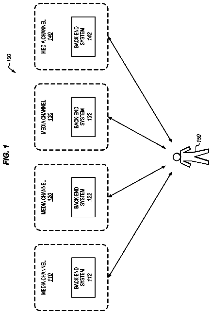
Sheet 1 of 29 from the published document. All sheets in the USPTO PDF
Methods, apparatus, and articles of manufacture for using location information to manage spillover in an audience monitoring system are disclosed. An example method involves identifying a first location of a portable metering device at a first time based on a plurality of location coordinates received from a location information system. The example method also involves generating media monitoring information corresponding to a media signal received at the first time. Additionally, the example method involves identifying the media monitoring information as being associated with a spillover signal in response to determining that a media delivery device is not located at the first location of the portable metering device at the first time.
Consuming media presentations generally involves listening to audio information and/or viewing video information such as, for example, radio programs, music, television programs, movies, still images, etc. Media-centric companies such as, for example, advertising companies, broadcasting networks, etc. are often interested in the viewing and listening interests of their audience to better market their products. A well-known technique often used to measure the exposure and/or number of audience members exposed to media involves awarding media exposure credit to a media presentation each time an audience member is exposed to the media presentation. The awarding of media exposure credit is often determined by monitoring the media consumption of audience members. The media consumption activities of audience members are often monitored using personal portable metering devices (PPMs), which are
1 of 29 drawing sheets so far from the published document, cropped to the drawing. Every sheet is in the USPTO PDF.
What the patent claimed, word for word. All of it is now free to use.
The present disclosure relates generally to media monitoring and, more particularly, to methods and apparatus for using audience member location information to monitor media consumption.
Consuming media presentations generally involves listening to audio information and/or viewing video information such as, for example, radio programs, music, television programs, movies, still images, etc. Media-centric companies such as, for example, advertising companies, broadcasting networks, etc. are often interested in the viewing and listening interests of their audience to better market their products. A well-known technique often used to measure the exposure and/or number of audience members exposed to media involves awarding media exposure credit to a media presentation each time an audience member is exposed to the media presentation.
The awarding of media exposure credit is often determined by monitoring the media consumption of audience members. The media consumption activities of audience members are often monitored using personal portable metering devices (PPMs), which are also known as portable metering devices and portable personal meters. A PPM is an electronic device that is typically worn (e.g., clipped to a belt or other apparel) or carried by an audience member. In general, PPMs are configured to use a variety of techniques to monitor the media consumption (e.g., viewing and/or listening activities) of a person. For example, one technique for monitoring media consumption involves detecting or collecting information (e.g., ancillary codes, signatures, etc.) from audio and/or video signals that are emitted or presented by media delivery devices (e.g., televisions, stereos, speakers, computers, etc.)
While wearing a PPM, an audience member or monitored individual performs their usual daily routine, which may include listening to the radio and/or other sources of audio media and/or watching television programs and/or other sources of visual media. As the audience member consumes (e.g., views, listens to, etc.) media, a PPM associated with (e.g., assigned to and carried by) that audience member may detect audio and/or video information associated with the media and generate monitoring data. In general, monitoring data may include any information that is representative of (or associated with) and/or that may be used to identify a particular media presentation (e.g., a song, a television program, a movie, a video game, etc.) For example, the monitoring data may include signatures that are collected or generated by the PPM based on the media, audio codes that are broadcast simultaneously with (e.g., embedded in) the media, etc.
As a person wearing a PPM travels throughout their household, the PPM receives audio and/or video content information provided by media delivery devices (e.g., televisions, radios, etc.) distributed throughout the household. The audio/video content may be encoded to facilitate subsequent identification of the audio/video content and/or the PPMs may be configured to use signature generation techniques to identify audio/video content received by the PPMs. In any case, each person's PPM may receive different audio/video content based on the person's unique location (e.g., within their household, at another location outside their household, etc.) and their location relative to the one or more media delivery devices to which they and their PPM are exposed.
Unfortunately, the typical household presents unique monitoring challenges to the PPM. For example, a typical household includes multiple media delivery devices, each configured to deliver media content to specific viewing and/or listening areas located within the home. A PPM, carried by a person who is located in one of the viewing and/or listening areas, is configured to detect any media content being delivered in the viewing and/or listening area and to credit the programming associated with the media content as having been consumed. Thus, the PPM operates on the premise that any media content detected by the PPM is associated with programming that was consumed by the person carrying the PPM. However, in some cases, a person's PPM may detect media content that is emitted by a media delivery device that is not located within the viewing or listening proximity of the person carrying the PPM thereby causing the detected programming to be improperly credited. The ability of the PPM to detect audio/video content being delivered outside of the viewing and/or listening proximity of the person carrying the PPM is an effect referred to as “spillover” because the media content being delivered outside of the viewing and/or listening proximity of the person carrying the PPM is described as “spilling over” into the area occupied by the person carrying the PPM. Spillover may occur, for example, in a case where a monitored individual in a bedroom is reading a book, but their PPM detects audio/video content delivered by a television in an adjacent living room, i.e., outside of their viewing/listening proximity, causing the audio/video content to be improperly credited as having been consumed.
Another effect, referred to as “hijacking” occurs when a person's PPM detects audio/video content being emitted from multiple media delivery devices at the same time. For example, an adult watching a television news program in a household kitchen may be located near a household family room in which children are watching a television cartoon program on a different television. Yet, the cartoon programming delivered by the family room television may, in some cases, have signals that overpower or “hijack” the signals associated with the news programming being emitted by the kitchen television. As a result, the adult's PPM may inaccurately credit the cartoon program as having been viewed by the adult and fail to credit the news program with any viewing. Still further, other common difficulties such as varying volume levels, varying audio/video content type (e.g., sparse, medium, rich, etc.), varying household transmission characteristics due to open/closed doors, movement and/or placement of furniture, acoustic characteristics of room layouts, wall construction, floor coverings, ceiling heights, etc. often lead to inaccurate audio/video content consumption detection by PPMs.
FIG. 1A illustrates an example area in which audience member location information may be collected and used to monitor media consumption.
FIG. 1B illustrates location analysis indicia overlaid onto the example household of FIG. 1A .
FIG. 1C illustrates an example location detection diagram overlaid onto the example household of FIG. 1A .
FIG. 2 is a block diagram of the example personal portable metering device of FIG. 1A .
FIG. 3 is a block diagram of one of the example base units of FIG. 1A .
FIGS. 4 and 5 depict example placement square grids overlaid onto example plan views of two different representative households in which the methods, apparatus and articles of manufacture described herein may be implemented.
FIGS. 6 and 7 depict example placement radial grids overlaid onto the households of FIGS. 3 and 4 .
FIGS. 8 and 9 depict media center-centric layouts in which bounded areas are used to illustrate the areas in which media content presented by each media delivery center may be detected by a PPM.
FIG. 10 depicts a detailed view of an example bounded area that may be used to implement the bounded areas of FIGS. 8 and 9 .
FIG. 11A is a flow diagram of an example method that may be used to collect time-stamped location information associated with the location of a PPM.
FIG. 11B is a flow diagram of an example method that may be used to collect time-stamped media monitoring information associated with media detected by the PPM.
FIG. 11C is a flow diagram of an example method that may be used to analyze the time-stamped location information and the time-stamped media monitoring information collected in connection with the example methods of FIGS. 11A and 11B .
FIG. 12A is a flow diagram of an example method that may be used to determine when a PPM is in a room or space that does not include any media delivery centers.
FIG. 12B is a flow diagram of an example method that may be used to generate media monitoring information based on the location of a PPM.
FIG. 13A is a flow diagram of an example method that may be used to output interference media codes.
FIG. 13B is a flow diagram of an example method that may be used to determine the location of a PPM within a room.
FIGS. 14A-14E are flow diagrams of example methods that may be used to enhance the accuracy of the location information detected using the PPM 104 .
FIG. 15 is a flow diagram of another example method that may be used to manage spillover.
FIG. 16 is a flow diagram of another example method that may be used to manage spillover.
FIG. 17 is a block diagram of an example processor system that may be used to implement some or all of the example methods and apparatus described herein.
FIG. 18 is another example location monitoring system that may be used to implement the methods and apparatus described herein.
FIGS. 19-21 are example sensor placement configurations that may be used to place the sensor units of FIG. 18 throughout a household.
FIG. 22 is a floor plan view of an example household illustrating an example placement configuration for the sensor units of FIG. 18 .
FIG. 23 is an example method that may be used to collect, manage and analyze media monitoring information and location information associated with media consumption activities of an audience member using the example location monitoring system of FIG. 18 .
FIG. 24 is an example method that may be implemented in combination with the example method of FIG. 23 and used to generate location information via the example monitoring system of FIG. 18 .
FIGS. 25A-25B illustrate an example method that may be implemented in combination with the example method of FIG. 23 and used to analyze location and media monitoring information via a central processing system.
Although the following discloses example systems including, among other components, software executed on hardware, it should be noted that such systems are merely illustrative and should not be considered as limiting. For example, it is contemplated that any or all of these hardware and software components could be embodied exclusively in hardware, exclusively in software, or in any combination of hardware and software. Accordingly, while the following describes example systems, persons having ordinary skill in the art will readily appreciate that the examples provided are not the only way to implement such systems.
In general, the example methods and apparatus described herein may be used to manage signal spillover and/or other sources of media monitoring inaccuracies in the course of an audience member's exposure to media sources or media presentations to more accurately assess the consumption of those media sources or presentations. As described in greater detail below, example methods and apparatus may be used to prevent signal spillover from adversely affecting results of media monitoring. In general, some of the example methods and apparatus for managing (e.g., preventing) signal spillover include using location detection technologies, placing media code interference apparatus throughout spaces and/or rooms in which media delivery devices are not placed, and using heuristic-based algorithms to more accurately determine the location of audience members and/or the locations of the media presentation devices via which media is consumed.
Although some of the example systems and methods are described below as monitoring media consumption by using location information to detect spillover in an audience monitoring system. The example systems and methods may also be implemented as described below to use location information to detect the location of a person in a home and to better understand media consumption habits of audience members. In some example implementations, the example methods and systems described below may use location information to determine the location of an audience member within a particular room or space of a household and to determine whether the audience member is sufficiently exposed to media presentations (e.g., radio programs, television programs, movies, computer information, etc.). An example implementation involves collecting location information associated with the location of an audience member to determine if the audience member is actively or effectively consuming a proximate or otherwise consumable media source. For example, if an audience member is within a room, space, or location that has a readily visible or audible media delivery device, the audience member is likely consuming any media presented by the media delivery device.
Although some example implementations may be used to determine that a person is generally located within a room or area of a household, other example implementations may be used to determine relatively more precise locations of a person within a particular room using, for example, X-Y location coordinates corresponding to a particular room or a particular household. Relatively more precise location coordinates provide an even better understanding of audience members' viewing habits. For example, although an audience member is located within a room having a television that is presenting or delivering a television program, the relatively more precise location information may indicate that the audience member is not facing the television, but is instead, for example, working on a computer and is not sufficiently exposed to the television to consume the television media. Of course, the example systems and methods described herein may use location information in any number of other ways to generate media monitoring information to better understand the viewing habits of consumers.
The example methods and apparatus described herein may be implemented using, for example, a PPM worn or carried by an audience member, location information systems (e.g., the global positioning system (GPS), radio frequency towers for triangulation, etc.), media code emitters, and media delivery devices, all of which may be used to collect and analyze audience member location information and/or media monitoring information. In this manner, media presentations (e.g., audio, video, still images, Internet information, computer information, etc.) may be given appropriate media exposure credit.
For purposes of clarity, the example methods and apparatus are described herein with respect to an example geographic area 100 shown in FIG. 1A . Although, the example geographic area 100 is shown by way of example as indoor and outdoor areas associated with a household 102 , the example methods and apparatus described herein may be used in any other area(s) or environment(s).
Location information is generally collected to determine rooms or locations of the household 102 within which an audience member is located while consuming or being exposed to media information. Location information may include, for example, a plurality of geographic, global, or position coordinates that may be used to analyze the movements of a person or an audience member from one location to another. As described in greater detail below, location information may be collected, obtained, generated, etc. using any suitable location detection devices, location detection systems, and/or location detection techniques. Specifically, the location detection devices described below may be worn or otherwise carried by a person or audience member.
Location information may be continuously collected in indoor environments and/or outdoor environments via, for example, an example PPM 104 that may be carried or worn by an audience member 106 as shown in FIG. 1A . In particular, the example PPM 104 may be configured to monitor the audience member 106 via one or more location detection devices and/or motion detection devices described below in connection with FIG. 2 . The location detection devices and motion detection devices may be configured to enable the example PPM 104 to collect audience member location information and/or motion information in indoor environments and/or outdoor environments. In this manner, when an audience member moves among indoor areas and outdoor areas a substantially continuous location history may be tracked or logged for each audience member to develop movement information.
Media monitoring information may include any information associated with media that is consumed (e.g., viewed, listened to, interacted with, etc.) by an audience member. Media presentations may include, for example, television programming, radio programming, movies, songs, advertisements, Internet information, and/or any other video information, audio information, still image information, and computer information to which a person may be exposed. Media monitoring information may be generated based on, for example, audio codes, signatures, radio frequency (RF) codes, and/or any other codes, information, or identifiers that may be extracted from or otherwise associated with a media presentation to which an audience member is exposed. As described in greater detail below, media monitoring information may be collected generated, obtained, etc. using any suitable media consumption detection device and/or any suitable media consumption detection technique.
In one implementation, the PPM 104 may tag media monitoring information with respective media location information to generate movement-annotated media monitoring information. In other words, in a substantially real-time process, the PPM 104 may substantially continuously combine time-stamped media monitoring information with time-stamped location information that corresponds to the locations at which the PPM 104 collected the time-stamped media monitoring information. In this manner, subsequent analyses can be used to determine the locations at which the audience member 106 was exposed to particular media. Alternatively, time-stamped media monitoring information may be combined with time-stamped location information in a post process. For example, time-stamped media monitoring information and time stamped location information may be stored within a memory (e.g., the memory 204 of FIG. 2 ) of the PPM 104 or may be stored in a storage device that is separate from the storage device (e.g., another information processing system) and may then be combined, joined, or otherwise interrelated in a subsequent process to generate location-annotated media monitoring information. Other information with which the collected information may be annotated includes, for example, audience identification information and PPM identification information.
Traditional methods for measuring media consumption typically track or log the media presentations to which an audience member is exposed and award a media exposure credit to a media source or presentation any time an audience member is in the vicinity of that media presentation or, more generally, within a distance of the media delivery device from which it is likely the audience member is consuming the media or from which it is likely a PPM will detect a media code associated with the media presentation. However, these traditional methods may produce inconsistent or inaccurate results due to spillover that occurs when the audience member 106 is in the vicinity of a media presentation, but is not adequately exposed to the media presentation. For example, within the household 102 , spillover may occur when the audience member 106 is located within a room having no media delivery device, but the PPM 104 detects media codes emanating from a media delivery device in another room. Logging the media codes that have spilled over from a space that is outside of the listening/viewing proximity of the audience member 106 results in an inaccurate representation of the media programs consumed by the audience member 106 .
As shown in FIG. 1A , the household 102 and the audience member 106 wearing the PPM 104 are located within the example geographic area 100 . As described below, the PPM 104 may be used to collect location information, motion information, and media monitoring information within the household 102 , outside of the household 102 , and within structures other than the household 102 .
The PPM 104 may be configured to substantially continuously generate, obtain, and/or collect media monitoring information, location information, and motion information. As described in greater detail below in connection with FIG. 2 , the PPM 104 may include one or more media detection devices used to detect presented media and generate or collect media monitoring information or media-related data based on, for example, audio signals, visual signals, radio frequency signals, etc. In addition, the PPM 104 may include one or more location or positioning devices that enable the PPM 104 to collect location or position information from one or more location information systems and/or to send location information to one or more location information systems. The example geographic area 100 includes one or more location information systems that may be used to communicate location information to/from the PPM 104 .
The location information systems may be implemented using, for example, one or more radio frequency (RF) transceiver towers represented in FIG. 1A by a RF transceiver tower 108 and/or one or more satellites represented in FIG. 1A by a satellite 110 . In addition, the interior environment of the household 102 may include one or more location information systems described below.
The PPM 104 may collect media monitoring information (e.g., ancillary codes, signatures, etc.) associated with any media (e.g., video, audio, movies, music, still pictures, advertising, computer information, etc.) to which the audience member 106 is exposed. For example, the PPM 104 may be configured to obtain audio codes, generate or collect signatures, etc. that may be used to identify video programs (e.g., DVD movies, television programming, etc.), audio programs (e.g., CD audio, radio programming, etc.), etc. In particular, the household 102 includes a plurality of media delivery centers 112 , each of which may include one or more media delivery devices such as, for example, a television, a radio, etc. as well as one or more media playback devices such as, for example, a DVD player, VCR, etc. Using one or more media detection devices described below in connection with FIG. 2 , the PPM 104 may collect media monitoring information associated with media presented or delivered by one or more of the media delivery centers 112 and to which the audience member 106 may be exposed.
Location information collected by the PPM 104 may be used to generate movement information and/or to analyze the movements of the audience member 106 . For example, movement information may be stored as a plurality of location coordinates or location information that may be converted to movement information during subsequent processing by generating movement paths that indicate or track the movements of an audience member. The PPM 104 may also include motion detection devices as described below in connection with FIG. 2 . Motion detection devices may be used in combination with location detection devices to more accurately determine the locations of the audience member 106 . For example, the motion detection devices may provide motion information such as, for example, acceleration, direction of travel, etc., which may be used to supplement location information and more accurately determine the locations of the audience member 106 .
The RF transceiver tower 108 may be used in combination with any RF communication technology such as, for example, a cellular communication technology (e.g., GSM, CDMA, TDMA, AMPS, etc.) In one example configuration, the RF transceiver tower 108 may be configured to transmit or broadcast position information and/or any type of signal that may be used by the PPM 104 to generate location information. For example, the RF transceiver tower 108 may transmit information having geographic location information and time codes. More specifically, the RF transceiver tower 108 may be associated with a particular or unique set of geographic location coordinates (i.e., geographic location information), that define or indicate the location of the RF transceiver tower 108 within a global positioning grid. The time codes may be associated with a time at which a particular signal is transmitted by the RF transceiver tower 108 .
The geographic location information and the time codes received from a plurality of RF transceiver towers may be used by the PPM 104 to perform triangulation processes to determine the location(s) of the PPM 104 . Triangulation processes are well known in the art and, thus, are not described further herein. Although the RF transceiver tower 108 is depicted as being located in an outdoor environment, the PPM 104 may include location technologies that communicate with the RF transceiver tower 108 when the PPM 104 is located within indoor environments (e.g., within the household 102 ) or outdoor environments.
The satellite 110 may also be used to communicate location information to/from the PPM 104 . For example, the satellite 110 may be used to implement any satellite positioning system (SPS) such as, for example, the global positioning system (GPS) that continuously broadcasts position-related information. In this manner, the PPM 104 may receive the position-related information from the satellite 110 to determine the location(s) and movement of the PPM 104 .
One or more location information systems may also be located within the household 102 . As shown in FIG. 1A , an example location information system includes a plurality of base units 114 . The base units 114 may include one or more location detection technologies, some of which are described below in connection with FIG. 3 . The base units 114 may be configured to work cooperatively with the PPM 104 to substantially continuously generate location information associated with the location of the PPM 104 as the audience member 106 moves among various areas within or around the household 102 . While the location detection technologies and capabilities are described as being integrated within the base units 114 , such technologies and capabilities could instead be incorporated within other devices or systems separate from the base units 114 .
The base units 114 may also be configured to detect media codes and/or deliver or emit media codes. For example, the base units 114 may be communicatively coupled to the media delivery centers 112 via audio and/or video communication paths and configured to obtain audio and/or video codes associated with media presentations delivered by the media delivery centers 112 . In this manner, the base units 114 may log time-stamped media monitoring information that indicates the media to which the audience member 106 may be exposed. As described in greater detail below in connection with example methods of FIGS. 11A-11C , the time-stamped media monitoring information may be compared and/or combined with time-stamped location information collected by the PPM 104 to determine the locations of the audience member 106 and the media presentations to which the audience member 106 was exposed.
The base units 114 may also generate media codes via media code generators as described in greater detail below in connection with FIG. 3 . The media code generators may be used to generate interference or disruptor media codes in areas proximate to base units 114 located within rooms or areas (e.g., hallways) having no media delivery centers. For example, a room 115 a of the household 102 has no media delivery centers while rooms 115 b and 115 c each includes the media delivery centers 112 . The base unit 114 located in the room 115 a may be configured to emit an interference media code that substantially disrupts or blocks media codes from the media delivery centers 112 that could otherwise spillover into the room 115 a . In this manner, when the PPM 104 is in the room 115 a , any media codes that spillover from the rooms 115 b and 115 c are overpowered, disrupted, blocked or otherwise obfuscated by the interference media codes broadcast by the base unit 114 in the room 115 a so that the PPM 104 only detects the interference media codes.
The interference media codes may be blank values or key values that, during subsequent analyses of the information, are used to discard or disregard information collected within rooms (e.g., the room 115 a ) or spaces (e.g., hallways) having no media delivery devices. The base unit 114 may emit the interference codes at various frequencies. For example, the frequencies at which the base units 114 emit interference codes may be selected to ensure that media codes that spill over from other rooms are disrupted (i.e., not detectable to a PPM located in the same room as the code disruptor) but allow the media codes of the room within which the PPM 104 is located to be detected by the PPM 104 . Alternatively, the base unit 114 may emit interference media codes at all of the frequencies at which the television/media audio codes of other rooms or spaces are transmitted. Additionally, the base unit 114 may include a microphone for sensing ambient noise/sound and may increase the strength at which the interference media codes are emitted when the ambient noise in the room increases. Thus, the interference media codes would have limited impact on (e.g., would not be perceptible by) people located within the vicinity of the base units 114 .
In an alternative or additional implementation, the base units 114 located in rooms or spaces having none of the media delivery centers 112 may be configured to emit a white noise or other type of interfering or masking noise or signal to prevent the PPM 104 from detecting any media codes that would otherwise spill over into the room or space having none of the media delivery centers 112 . The white noise or other type of interfering or masking noise may be delivered at a power level, strength, or volume that the human brain can tune out or easily disregard without causing annoyance (or at least minimizing the level of annoyance caused) to humans.
The base units 114 may be implemented using consoles that are placed anywhere within the rooms or spaces of a household. Alternatively or additionally, the base units 114 may be implemented as wall-mountable devices that can, for example, be plugged directly into an alternating current (AC) electrical outlet.
For cases in which the base units 114 are installed or placed only in rooms or spaces having media delivery centers (e.g., the media delivery centers 112 ), the base units 114 may be configured to emit location information associated only with their respective rooms. In this case, transmission fields of each of the base units 114 may be shaped using a shielding material to prevent, eliminate, or reduce spillover of the location information into adjacent rooms. For example, shielding materials may be operatively coupled to the base units 114 to shape RF emission fields to prevent the base units 114 from spilling RF information into adjacent rooms or spaces by positioning the shielding material to block the transmission of signals toward any walls shared by adjacent rooms. For example, the shielding material may be applied to the base units 114 to direct the emitted RF energy in a direction toward the center of the room or space corresponding to the base unit 114 . The metal shield may also be positioned to block the transmission of signals toward any walls shared by adjacent rooms. Using such a shield, a location code signal propagates away from the walls shared by adjacent rooms so that spillover of the location codes into the adjacent room is limited or substantially eliminated. Although the location codes and/or other information emitted by the base units 114 may reflect off of one or more surfaces in the room, the reflected signal would be substantially weakened to significantly degrade or minimize the ability of the reflected signal to travel through the wall. In this manner, if the PPM 104 detects audio codes and the location codes, then the corresponding programming is associated with actual viewing. If instead the audio codes are detected but the location codes are not detected, then the detected audio codes may be disregarded as being caused by spillover.
Example movement information is shown in FIG. 1A as a first movement path 116 a , a second movement path 116 b , and a third movement path 116 c . The first movement path 116 a indicates that the audience member 106 moved from one room to another. The second movement path 116 b indicates that the audience member 106 moved from a couch 117 to the media delivery center 112 and back. The third movement path 116 c indicates that the audience member 106 moved from the inside of the household 102 to a location outside of the household 102 . The example movement paths 116 a - c may be generated using location information collected by the PPM 104 in combination with any one or more suitable location information systems (e.g., the RF transceiver tower 108 , the satellite 110 , the base units 114 , etc.). For example, the location information used to generate the movement paths 116 a and 116 b may be generated using information received from the RF transceiver towers 108 , the base units 114 , or a combination thereof.
The location information used to generate the movement path 116 c may include location information generated using location information systems that function for indoor use and/or outdoor use. One such location information system may be, for example, the RF transceiver tower 108 . Alternatively, location information associated with the movement path 116 c may be generated using a combination of location information systems such as, for example, a first location information system that functions primarily or only in indoor environments and a second location information system that functions primarily or only in outdoor environments. In that case, the first location information system for indoor use may be, for example, the base units 114 and the second location information system may be, for example, the satellite 110 . Using two location information systems (e.g., the base units 114 and the satellite 110 ) in combination may require a handoff process to ensure that the PPM 104 transitions substantially seamlessly from working with one location information system to working with another. An example handoff process may include a software routine that continuously searches for the signals from both location information systems and works with the location information system providing the strongest signal. Other software and/or circuitry may provide hysteresis to enable minimum/maximum threshold levels of signal strength to be used to prevent the PPM 104 from continuously switching between location information systems.
The household 102 may also include a plurality of room differentiators 118 a and 118 b . The room differentiators 118 a and 118 b may be placed in rooms and/or areas within rooms or spaces that are prone to spillover. For example, the room differentiators 118 a and 118 b may be placed on or adjacent to opposing surfaces of a wall (e.g., a wall 119 ) separating two rooms or spaces. Each of the room differentiators 118 a and 118 b is configured to emit a code (e.g., an ancillary location code) or a signal at a particular frequency uniquely associated with a respective room. The room differentiators 118 a and 118 b may include a short range signal broadcasting or signal emitting technology that is easily attenuated by walls. In this manner, if the audience member 106 is close to the wall 119 and the PPM 104 detects media codes from two different media delivery centers 112 , the short range codes emitted by the room differentiators may be used by the PPM 104 to determine in which room the PPM 104 is located and, thus, to which media delivery center 112 the audience member 106 is exposed. The PPM 104 will only detect the short range code from the room differentiator located within the same room as the audience member 106 because the short range codes are configured to be substantially attenuated by walls. One such technology that can be tuned to be easily attenuated by walls includes ultrasound emitters. In such a configuration, the PPM 104 will include an ultrasound receiver. Of course, any other suitable technology could be used instead. For example, the room differentiators 118 a and 118 b could be implemented using 802.11 emitters that are set to a low enough signal strength to be substantially attenuated by the wall 119 .
In an example implementation in which the room differentiators 118 a and 118 b are implemented using 802.11 emitters, each of the room differentiators 118 a and 118 b may be configured to emit signals at a low power (i.e., weak signals), at a different frequency, and/or having different location codes. The differentiators 118 a and 118 b may be placed near or on the wall 119 in each room such that the audience member 106 carrying the PPM 104 in the room 115 c will be closer to the differentiator 118 b because the differentiator 118 b is located in the same room (e.g., the room 115 c ) in which the PPM 104 is located. If the PPM 104 detects signals from both of the differentiators 118 a and 118 b at substantially the same time, then the stronger signal is used to identify the one of the differentiators 118 a and 118 b that is in the same room as the PPM 104 . In this manner, the PPM 104 may log the room within which it is located and use this information in combination with location information and media monitoring information to determine a media presentation consumed by the audience member 106 .
The information received from one of the differentiators 118 a and 118 b that is within the same room as the PPM 104 may be logged by the PPM 104 and used during subsequent analyses to determine the room in which the PPM 104 was collecting audio codes from media programs. If it is determined during subsequent analyses that the room within which the PPM 104 is located contains a television or other media delivery device (e.g., the media delivery centers 112 ), any audio codes detected by the PPM 104 are associated with actual viewing. On the other hand, if the identified room does not contain a television or other media delivery device, then any audio codes detected by the PPM 104 are identified as spillover codes and are disregarded.
The room differentiators 118 a and 118 b may be implemented using a wall-mountable device that plugs directly into AC electrical outlets. Alternatively, the room differentiators 118 a and 118 b may be implemented using a console mounted to a wall or stored on the floor. A broadcasting transducer (e.g., a speaker) may be operatively coupled to and mounted within each of the room differentiators 118 a and 118 b . Alternatively, one or more broadcasting transducers may be tethered to each of the room differentiators 118 a and 118 b and distributed evenly along opposing sides of a wall (e.g., the wall 119 ).
The description continues in the full USPTO document.
About 6,350 words. The USPTO PDF has it with every drawing.
Fees are due 3.5, 7.5 and 11.5 years after grant. This patent expired on October 17, 2025, so the fee marked "not paid" was the one that went unpaid.
METHODS AND APPARATUS FOR USING LOCATION INFORMATION TO MANAGE SPILLOVER IN AN AUDIENCE MONITORING SYSTEM
Filed Mar 2007 · published Nov 2007Methods and apparatus for using location information to manage spillover in an audience monitoring system
Filed Mar 2007 · granted Jun 2010METHODS AND APPARATUS FOR USING LOCATION INFORMATION TO MANAGE SPILLOVER IN AN AUDIENCE MONITORING SYSTEM
Filed Apr 2010 · published Aug 2010Methods and apparatus for using location information to manage spillover in an audience monitoring system
Filed Apr 2010 · granted Jul 2015METHODS AND APPARATUS FOR USING LOCATION INFORMATION TO MANAGE SPILLOVER IN AN AUDIENCE MONITORING SYSTEM
Filed Jul 2015 · published Nov 2015Methods and apparatus for using location information to manage spillover in an audience monitoring system
Filed Jul 2015 · granted Oct 2017Earlier publications, parents and continuations. None of them can still be enforced, or this patent would not be listed.
Prior art cited by the examiner or applicant. Useful when you check your own idea for novelty.
Everything on this page comes from the documents linked above.