 Lapsed, fee not paid12 drawings
Hardware & Electronics · US 9,794,301 B1
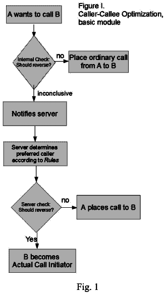
Telephone session initiation system
A method is presented that allows for coordination between parties wanting to communicate.
US 9,794,397 B2 · Assignee: LG ELECTRONICS INC. · Inventors: Min; Jihye et al.
Sheet 1 of 45 from the published document. All sheets in the USPTO PDF
A watch type mobile terminal configured to be wearable on a wrist and a control method thereof are provided. The watch type mobile terminal includes a display unit configured to display screen information, a terminal body configured to allow the display unit to be installed therein and disposed on the wrist, a sensing unit configured to sense a position in which the mobile terminal is worn, and a controller configured to allocate a particular region of the display unit, as a control region for receiving a control command based on the sensing result, and process a user's touch input applied to the control region, as a control command for controlling an operation of the mobile terminal.
Terminals may be generally classified as mobile/portable terminals or stationary terminals according to their mobility. Mobile terminals may also be classified as handheld terminals or vehicle mounted terminals according to whether or not a user can directly carry the terminal. Mobile terminals have become increasingly more functional. Examples of such functions include data and voice communications, capturing images and video via a camera, recording audio, playing music files via a speaker system, and displaying images and video on a display. Some mobile terminals include additional functionality which supports game playing, while other terminals are configured as multimedia players. More recently, mobile terminals have been configured to receive broadcast and multicast signals which permit viewing of content such as videos and television programs. Efforts are ongoing to support and inc
1 of 45 drawing sheets so far from the published document, cropped to the drawing. Every sheet is in the USPTO PDF.
What the patent claimed, word for word. All of it is now free to use.
Pursuant to 35 U.S.C. §119(a), this application claims the benefit of earlier filing date and right of priority to Korean Application Nos. 10-2013-0123519, filed on Oct. 16, 2013, and 10-2013-0147745, filed on Nov. 29, 2013, the contents of which are all hereby incorporated by reference herein in their entirety.
The present disclosure relates to a mobile terminal and, more particularly, to a watch type mobile terminal that can be worn on a user's wrist, and a control method thereof.
Terminals may be generally classified as mobile/portable terminals or stationary terminals according to their mobility. Mobile terminals may also be classified as handheld terminals or vehicle mounted terminals according to whether or not a user can directly carry the terminal.
Mobile terminals have become increasingly more functional. Examples of such functions include data and voice communications, capturing images and video via a camera, recording audio, playing music files via a speaker system, and displaying images and video on a display. Some mobile terminals include additional functionality which supports game playing, while other terminals are configured as multimedia players. More recently, mobile terminals have been configured to receive broadcast and multicast signals which permit viewing of content such as videos and television programs.
Efforts are ongoing to support and increase the functionality of mobile terminals. Such efforts include software and hardware improvements, as well as changes and improvements in the structural components.
Prompted by the improvement, terminals have evolved toward various designs, and thus, wearable terminals that may be worn on parts of users' bodies have come to prominence, for which necessity for a user interface according to characteristics of wearable terminals has emerged.
Therefore, an aspect of the detailed description is to provide a watch type mobile terminal, which can be worn on a user's wrist, capable of enhancing user convenience in displaying information thereon, and a control method thereof.
To achieve these and other advantages and in accordance with the purpose of this specification, as embodied and broadly described herein, a watch type mobile terminal configured to be wearable on a wrist may include: a display unit configured to display screen information; a terminal body configured to allow the display unit to be installed therein and disposed on the wrist; a sensing unit configured to sense a position in which the mobile terminal is worn; and a controller configured to allocate a particular region of the display unit, as a control region for receiving a control command based on the sensing result, and process a user's touch input applied to the control region, as a control command for controlling an operation of the mobile terminal.
In an exemplary embodiment of the present disclosure, the controller may allocate a region for the user to relatively easily access, as a control region, according to a position in which the mobile terminal is worn, by using the sensing result, and the position of the control region may vary depending on which of the user's wrists the mobile terminal is worn.
In an exemplary embodiment of the present disclosure, in a first state in which the mobile terminal is worn on the user's left wrist, the controller may allocate the control region to one side of the display unit, and in a second state in which the mobile terminal is worn on the user's right wrist, the controller may allocate the control region to the other side of the display unit.
In an exemplary embodiment of the present disclosure, in the first state, the control region may be positioned in a lower right portion of the display unit based on a virtual central axis of the terminal body, and in the second state, the control region may be positioned in lower left portion of the display unit based on the virtual central axis of the terminal body.
In an exemplary embodiment of the present disclosure, when a function icon for receiving a control command related to an operation of the mobile terminal needs to be output, the controller may output the function icon to the allocated control region.
In an exemplary embodiment of the present disclosure, in a state in which the function icon is not output to the allocated control region, the particular region may have the same attribute as that of other region.
In an exemplary embodiment of the present disclosure, in a state in which the function icon is not output to the allocated control region, when a pre-set type touch is applied to the allocated control region, at least one among a function icon related to the current operation of the mobile terminal and a basic operation function icon of the mobile terminal may be output to the allocated control region.
In an exemplary embodiment of the present disclosure, the sensing unit may sense a movement of the wrist on which the mobile terminal is worn, and when the sensed movement of the wrist exceeds a reference range, the controller may re-allocate a region, at least a portion thereof being different from the particular region, as a control region such that the position of the control region is changed in response to the movement of the wrist.
In an exemplary embodiment of the present disclosure, in a state in which certain screen information is displayed on the display unit, when an event occurs in the mobile terminal, information related to the generated event may be displayed in at least one region of the display unit, excluding the control region, and at least one function icon for receiving a control command related to the generated event may be displayed in the control region.
In an exemplary embodiment of the present disclosure, the sensing unit may be configured to sense at least one among a movement of the mobile terminal and a direction of the user's eyes with respect to the display unit, and the controller may determine a position in which the information related to the event is to be displayed in consideration of at least one of the movement of the mobile terminal and the direction of the user's eyes.
In an exemplary embodiment of the present disclosure, the sensing unit may sense that the terminal body is rotated based on a virtual plane parallel to the display unit, and the controller may control the display unit such that screen information displayed on the display unit is maintained to be output in the direction of the user's eyes even though the terminal body is rotated.
In an exemplary embodiment of the present disclosure, the screen information displayed on the display unit may be shifted in an opposite direction of the rotational direction of the terminal body.
To achieve these and other advantages and in accordance with the purpose of this specification, as embodied and broadly described herein, a watch type mobile terminal configured to be wearable on a wrist may include: a terminal body disposed on the wrist; a display unit installed in the terminal body and configured to output clock information and allow for a touch input; a situational information unit configured to collect situational information in environment surrounding the terminal body; and a controller configured to reflect the collected situational information in the clock information output on the display unit.
In an exemplary embodiment of the present disclosure, when a pre-set touch input is applied to the clock information, the controller may control the display unit to output at least a portion of the collected situational information.
In an exemplary embodiment of the present disclosure, the clock information may include an hour hand image, a minute hand image, and a background image representing the current time, and a form of at least one among the hour hand image, the minute hand image, and the background image may be determined based on the collected situational information.
In an exemplary embodiment of the present disclosure, the watch type mobile terminal may further include: a memory configured to store mode information regarding a plurality of situation modes classified based on the collected situational information, wherein the controller may control the display unit such that the clock information corresponds to a situation mode related to the current situational information in environment surrounding the terminal body, among the plurality of situation modes.
In an exemplary embodiment of the present disclosure, when the collected situational information is updated, if a situation mode related to the updated situational information is different from a situation mode related to the current situational information in environment surrounding the terminal body, the controller may change the clock information to correspond to the situation mode related to the updated situational information, and if the situation mode related to the updated situational information is the same as the situation mode related to the current situational information in environment surrounding the terminal body, the controller may maintain the clock information.
In an exemplary embodiment of the present disclosure, when a pre-set touch input is applied to the clock information, the controller may output at least one among a virtual hour hand image and a virtual minute hand image for setting time information related to a particular function to the display unit.
In an exemplary embodiment of the present disclosure, at least one of the virtual hour hand image and the virtual minute hand image may be movable by a drag touch, and by using time information indicated by at least one among the virtual hour hand image and the virtual minute hand image moved by the drag touch, when the current time corresponds to a pre-set time related to the time information, the controller may execute the particular function.
In an exemplary embodiment of the present disclosure, when setting of the time information using at least one of the virtual hour hand image and the virtual minute hand image is completed, the controller may output a plurality of icons corresponding to a plurality of selectable functions to the display unit, and when any one of the plurality of icons is selected, the controller may designate the selected function as the particular function and execute the particular function.
In an exemplary embodiment of the present disclosure, when the current time is close to a set time related to the time information, the controller may change the clock information in order to inform the fact that the set time nears.
In an exemplary embodiment of the present disclosure, the collected situation information may include position information of the terminal body, and when setting of the time information is completed and the user who wears the terminal body has moved by a time corresponding to the set time information from the current position of the terminal body based on the position information, the controller may output place information related to a place within a range in which the user can arrive.
In an exemplary embodiment of the present disclosure, the situational information unit may collect information regarding a movement of the terminal body, and when the movement of the terminal body exceeds a reference range, the controller may determine that the user who wears the terminal body on his or her wrist is doing exercise, and output clock information related to the exercise based on the determination result.
In an exemplary embodiment of the present disclosure, when the movement of the terminal body is repeated in a particular pattern, the controller may reflect the number of times of the repeated movements correspond to the pattern in the clock information.
In an exemplary embodiment of the present disclosure, the situational information collected through the situational information unit may include position information of the terminal body and position information of an object spaced apart from the terminal body, and the controller may control the display unit to reflect the relative position information of the object with respect to the terminal body in the clock information.
In an exemplary embodiment of the present disclosure, the situational information unit may collect information regarding weather of an area in which the terminal body is positioned and information regarding a movement of the terminal body, and when the movement of the terminal body corresponds to a pre-set gesture maintained for a particular period of time, the controller may reflect the collected situational information related to weather in the clock information.
Further scope of applicability of the present application will become more apparent from the detailed description given hereinafter. However, it should be understood that the detailed description and specific examples, while indicating preferred embodiments of the invention, are given by way of illustration only, since various changes and modifications within the spirit and scope of the invention will become apparent to those skilled in the art from the detailed description.
The accompanying drawings, which are included to provide a further understanding of the invention and are incorporated in and constitute a part of this specification, illustrate exemplary embodiments and together with the description serve to explain the principles of the invention.
In the drawings:
FIG. 1 is a block diagram of a mobile terminal according to an exemplary embodiment disclosed in the present disclosure.
FIGS. 2A and 2B are conceptual views of a communication system in which the mobile terminal according to an exemplary embodiment of the present disclosure is operable.
FIGS. 3A and 3B are conceptual vies illustrating a flexible display unit when a display unit of the mobile terminal according to an exemplary embodiment of the present disclosure is formed as a flexible display unit.
FIG. 4 is a flow chart illustrating a method for displaying information in a watch type mobile terminal according to an exemplary embodiment of the present disclosure.
FIGS. 5A, 5B, 5C, and 5D are conceptual views illustrating a control method according to the flow chart illustrated in FIG. 4 .
FIG. 6 is a conceptual view illustrating a method for allocating a control region in a mobile terminal according to an exemplary embodiment of the present disclosure.
FIGS. 7A, 7B, 8A, 8B, 8C, 9A, and 9B are conceptual views illustrating a method for displaying a control region in a mobile terminal according to an exemplary embodiment of the present disclosure.
FIGS. 10A, 10B, 11A, 11B, 11C, and 11D are conceptual views illustrating a method for changing a display state of screen information according to a position of a mobile terminal according to an exemplary embodiment of the present disclosure.
FIG. 12 is a flow chart illustrating an example of a method for displaying clock information in a mobile terminal according to an exemplary embodiment of the present disclosure.
FIGS. 13A through 13D are conceptual views illustrating a control method according to the flow chart illustrated in FIG. 12 .
FIGS. 14A and 14B are conceptual views illustrating a method for outputting situational information corresponding to a touch input applied to clock information in a mobile terminal according to an exemplary embodiment of the present disclosure.
FIGS. 15A through 15C are conceptual views illustrating a method for setting time information to perform a particular function using clock information in a mobile terminal according to an exemplary embodiment of the present disclosure.
FIG. 16 is a conceptual view illustrating a method for changing clock information in relation to time information set in a mobile terminal according to an exemplary embodiment of the present disclosure.
FIGS. 17A and 17B are conceptual views illustrating a method for providing information related to an exercise for a user by using collected situational information in a mobile terminal according to an exemplary embodiment of the present disclosure.
FIG. 18 is a conceptual view illustrating a method for providing information regarding a place around the user by using collected information for the user in a mobile terminal according to an exemplary embodiment of the present disclosure.
FIGS. 19A and 19B are conceptual views illustrating relative position information between a terminal body and an object spaced apart from the terminal body by using collected situational information in a mobile terminal according to an exemplary embodiment of the present disclosure.
FIGS. 20A and 20B are conceptual views illustrating a method for reflecting collected situational information in clock information in response to a pre-set gesture in a mobile terminal according to an exemplary embodiment of the present disclosure.
FIG. 21 is a conceptual view illustrating an example of outputting schedule information in response to a touch input applied to clock information in a mobile terminal according to an exemplary embodiment of the present disclosure.
FIG. 22 is a conceptual view illustrating an example in which clock information is changed according to collected situational information in a mobile terminal according to an exemplary embodiment of the present disclosure.
FIG. 23 is a conceptual view illustrating a method for displaying a call time in relation to clock information in a mobile terminal according to an exemplary embodiment of the present disclosure.
FIG. 24 is a conceptual view illustrating a method of displaying different types of events as occur and a control method thereof in a mobile terminal according to an exemplary embodiment of the present disclosure.
FIGS. 25A and 25B are conceptual views illustrating a method for displaying a remaining battery capacity in relation to clock information in a mobile terminal according to an exemplary embodiment of the present disclosure.
FIG. 26 is a conceptual view illustrating a method for displaying information received from other electronic device by using an edge region of a display unit in a mobile terminal according to an exemplary embodiment of the present disclosure.
FIG. 27 is a conceptual view illustrating an example in which a mobile terminal according to an exemplary embodiment of the present disclosure is controlled in response to a pre-set gesture.
FIG. 28 is a conceptual view illustrating examples in which clock information is displayed according to orientation of a terminal body in a mobile terminal according to an exemplary embodiment of the present disclosure.
The embodiments of the present invention will now be described with reference to the accompanying drawings, in which like numbers refer to like elements throughout although the embodiments are different, and a description of the like elements a first embodiment will be used for those of the different embodiment. In the following description, usage of suffixes such as ‘module’, ‘part’ or ‘unit’ used for referring to elements is given merely to facilitate explanation of the present invention, without having any significant meaning by itself. In describing the present invention, if a detailed explanation for a related known function or construction is considered to unnecessarily divert the gist of the present invention, such explanation has been omitted but would be understood by those skilled in the art. The accompanying drawings of the present invention aim to facilitate understanding of the present invention and should not be construed as limited to the accompanying drawings.
Mobile terminals described in the present disclosure may include mobile phones, smart phones, notebook computers, tablet computers, digital broadcast receivers, PDAs (Personal Digital Assistants), PMPs (Portable Multimedia Player), navigation devices, slate PCs, tablet PCs, ultra-books, and the like. However, it would be understood by a person skilled in the art that the configuration according to embodiments of the present invention can be also applicable to the fixed types of terminals such as digital TVs, desk top computers, and the like, except for any elements especially configured for a mobile purpose.
FIG. 1 is a block diagram of a mobile terminal according to an embodiment of the present invention.
The mobile terminal 100 may include a wireless communication unit 110 , an A/V (Audio/Video) input unit 120 , a user input unit 130 , a sensing unit 140 , an output unit 150 , a memory 160 , an interface unit 170 , a controller 180 , and a power supply unit 190 , etc. FIG. 1 shows the mobile terminal as having various components, but it should be understood that implementing all of the illustrated components is not a requirement. Greater or fewer components may alternatively be implemented.
The elements of the mobile terminal will be described in detail as follows.
The wireless communication unit 110 typically includes one or more modules allowing radio communication between the mobile terminal 100 and a wireless communication system or a network in which the mobile terminal is located. For example, the wireless communication unit may include at least one of a broadcast receiving module 111 , a mobile communication module 112 , a wireless Internet module 113 , a short-range communication module 114 , and a location information module 115 .
The broadcast receiving module 111 receives broadcast signals and/or broadcast associated information from an external broadcast management server (or other network entity) via a broadcast channel.
The broadcast channel may include a satellite channel and/or a terrestrial channel. The broadcast management server may be a server that generates and transmits a broadcast signal and/or broadcast associated information or a server that receives a previously generated broadcast signal and/or broadcast associated information and transmits the same to a terminal. The broadcast signal may include a TV broadcast signal, a radio broadcast signal, a data broadcast signal, and the like. Also, the broadcast signal may further include a broadcast signal combined with a TV or radio broadcast signal.
The broadcast associated information may refer to information associated with a broadcast channel, a broadcast program or a broadcast service provider. The broadcast associated information may also be provided via a mobile communication network and, in this case, the broadcast associated information may be received by the mobile communication module 112 .
The broadcast associated information may exist in various forms. For example, it may exist in the form of an electronic program guide (EPG) of digital multimedia broadcasting (DMB), electronic service guide (ESG) of digital video broadcast-handheld (DVB-H), and the like.
The broadcast receiving module 111 may be configured to receive signals broadcast by using various types of broadcast systems. In particular, the broadcast receiving module 111 may receive a digital broadcast by using a digital broadcast system such as multimedia broadcasting-terrestrial (DMB-T), digital multimedia broadcasting-satellite (DMB-S), digital video broadcast-handheld (DVB-H), the data broadcasting system known as media forward link only (MediaFLO®), integrated services digital broadcast-terrestrial (ISDB-T), etc. The broadcast receiving module 111 may be configured to be suitable for every broadcast system that provides a broadcast signal as well as the above-mentioned digital broadcast systems.
Broadcast signals and/or broadcast-associated information received via the broadcast receiving module 111 may be stored in the memory 160 .
The mobile communication module 112 transmits and/or receives radio signals to and/or from at least one of a base station, an external terminal and a server. Such radio signals may include a voice call signal, a video call signal or various types of data according to text and/or multimedia message transmission and/or reception.
The wireless Internet module 113 supports wireless Internet access for the mobile terminal. This module may be internally or externally coupled to the terminal. The wireless Internet access technique implemented may include a WLAN (Wireless LAN) (Wi-Fi), Wibro (Wireless broadband), Wimax (World Interoperability for Microwave Access), HSDPA (High Speed Downlink Packet Access), or the like.
The short-range communication module 114 is a module for supporting short range communications. Some examples of short-range communication technology include Bluetooth™, Radio Frequency IDentification (RFID), Infrared Data Association (IrDA), Ultra-WideBand (UWB), ZigBee™, and the like.
The location information module 115 is a module for checking or acquiring a location (or position) of the mobile terminal. A typical example of the location information module is a GPS (Global Positioning System) or a WiFi (Wireless Fidelity) module.
With reference to FIG. 1 , the NV input unit 120 is configured to receive an audio or video signal. The NV input unit 120 may include a camera 121 and a microphone 122 . The camera 121 processes image data of still pictures or video obtained by an image capture device in a video capturing mode or an image capturing mode. The processed image frames may be displayed on a display unit 151 .
The image frames processed by the camera 121 may be stored in the memory 160 (or other storage medium) or transmitted via the wireless communication unit 110 . Two or more cameras 121 may be provided according to the configuration of the mobile terminal.
The microphone 122 may receive sounds (audible data) via a microphone in a phone call mode, a recording mode, a voice recognition mode, and the like, and can process such sounds into audio data. The processed audio (voice) data may be converted for output into a format transmittable to a mobile communication base station via the mobile communication module 112 in case of the phone call mode. The microphone 122 may implement various types of noise canceling (or suppression) algorithms to cancel (or suppress) noise or interference generated in the course of receiving and transmitting audio signals.
The user input unit 130 may generate input data from commands entered by a user to control various operations of the mobile terminal. The user input unit 130 may include a keypad, a dome switch, a touch pad, a jog wheel, a jog switch, and the like.
The sensing unit 140 detects a current status (or state) of the mobile terminal 100 such as an opened or closed state of the mobile terminal 100 , a location of the mobile terminal 100 , the presence or absence of user contact with the mobile terminal 100 (i.e., touch inputs), the orientation of the mobile terminal 100 , an acceleration or deceleration movement and direction of the mobile terminal 100 , etc., and generates commands or signals for controlling the operation of the mobile terminal 100 . For example, when the mobile terminal 100 is implemented as a slide type mobile phone, the sensing unit 140 may sense whether the slide phone is opened or closed. In addition, the sensing unit 140 can detect whether or not the power supply unit 190 supplies power or whether or not the interface unit 170 is coupled with an external device.
The output unit 150 is configured to provide outputs in a visual, audible, and/or tactile manner (e.g., audio signal, video signal, alarm signal, vibration signal, etc.). The output unit 150 may include the display unit 151 , an audio output module 153 , an alarm unit 154 , a haptic module 155 , and the like.
The display unit 151 may display (output) information processed in the mobile terminal 100 . For example, when the mobile terminal 100 is in a phone call mode, the display unit 151 may display a User Interface (UI) or a Graphic User Interface (GUI) associated with a call or other communication (such as text messaging, multimedia file downloading, etc.). When the mobile terminal 100 is in a video call mode or image capturing mode, the display unit 151 may display a captured image and/or received image, a UI or GUI that shows videos or images and functions related thereto, and the like.
The display unit 151 may include at least one of a Liquid Crystal Display (LCD), a Thin Film Transistor-LCD (TFT-LCD), an Organic Light Emitting Diode (OLED) display, a flexible display, a three-dimensional (3D) display, and an e-ink display.
Some of them may be configured to be transparent or light-transmissive to allow viewing of the exterior, which may be called transparent displays. A typical transparent display may be, for example, a TOLED (Transparent Organic Light Emitting Diode) display, or the like. Through such configuration, the user can view an object positioned at the rear side of the terminal body through the region occupied by the display unit 151 of the terminal body.
The mobile terminal 100 may include two or more display units according to its particular desired embodiment. For example, a plurality of display units may be separately or integrally disposed on one surface of the mobile terminal, or may be separately disposed on mutually different surfaces.
Also, the display unit 151 may be configured as a stereoscopic display unit 152 displaying a stereoscopic image.
Here, the stereoscopic image may be a three-dimensional (3D) stereoscopic image, and the 3D stereoscopic image is an image refers to an image making a viewer feel that a gradual depth and reality of an object on a monitor or a screen is the same as a reality space. A 3D stereoscopic image is implemented by using binocular disparity. Binocular disparity refers to disparity made by the positions of two eyes. When two eyes view different 2D images, the images are transferred to the brain through the retina and combined in the brain to provide the perception of depth and reality sense.
The stereoscopic display unit 152 may employ a stereoscopic display scheme such as stereoscopic scheme (a glass scheme), an auto-stereoscopic scheme (glassless scheme), a projection scheme (holographic scheme), or the like. Stereoscopic schemes commonly used for home television receivers, or the like, include Wheatstone stereoscopic scheme, or the like.
The auto-stereoscopic scheme includes, for example, a parallax barrier scheme, a lenticular scheme, an integral imaging scheme, or the like. The projection scheme includes a reflective holographic scheme, a transmissive holographic scheme, or the like.
In general, a 3D stereoscopic image is comprised of a left image (a left eye image) and a right image (a right eye image). According to how left and right images are combined into a 3D stereoscopic image, the 3D stereoscopic imaging method is divided into a top-down method in which left and right images are disposed up and down in a frame, an L-to-R (left-to-right, side by side) method in which left and right images are disposed left and right in a frame, a checker board method in which fragments of left and right images are disposed in a tile form, an interlaced method in which left and right images are alternately disposed by columns and rows, and a time sequential (or frame by frame) method in which left and right images are alternately displayed by time.
Also, as for a 3D thumbnail image, a left image thumbnail and a right image thumbnail are generated from a left image and a right image of the original image frame, respectively, and then combined to generate a single 3D thumbnail image. In general, thumbnail refers to a reduced image or a reduced still image. The thusly generated left image thumbnail and the right image thumbnail are displayed with a horizontal distance difference therebetween by a depth corresponding to the disparity between the left image and the right image on the screen, providing a stereoscopic space sense.
A left image and a right image required for implementing a 3D stereoscopic image is displayed on the stereoscopic display unit 152 by a stereoscopic processing unit 152 a . The stereoscopic processing unit may receive the 3D image and extract the left image and the right image, or may receive the 2D image and change it into a left image and a right image.
Meanwhile, when the display unit 151 and a sensor (referred to as a ‘touch sensor’, hereinafter) for detecting a touch operation are overlaid in a layered manner to form a touch screen, the display unit 151 may function as both an input device and an output device. The touch sensor may have a form of a touch film, a touch sheet, a touch pad, and the like.
The touch sensor may be configured to convert pressure applied to a particular portion of the display unit 151 or a change in the capacitance or the like generated at a particular portion of the display unit 151 into an electrical input signal. The touch sensor may be configured to detect the pressure when a touch is applied, as well as the touched position and area.
When there is a touch input with respect to the touch sensor, a corresponding signal (signals) are transmitted to a touch controller. The touch controller processes the signals and transmits corresponding data to the controller 180 . Accordingly, the controller 180 may recognize which portion of the display unit 151 has been touched.
With reference to FIG. 1 , a proximity sensor 141 may be disposed within or near the touch screen. The proximity sensor 141 is a sensor for detecting the presence or absence of an object relative to a certain detection surface or an object that exists nearby by using the force of electromagnetism or infrared rays without a physical contact. Thus, the proximity sensor 141 has a considerably longer life span compared with a contact type sensor, and it can be utilized for various purposes.
Examples of the proximity sensor 141 may include a transmission type photoelectric sensor, a direct reflection type photoelectric sensor, a mirror-reflection type photoelectric sensor, an RF oscillation type proximity sensor, a capacitance type proximity sensor, a magnetic proximity sensor, an infrared proximity sensor, and the like. In case where the touch screen is the capacitance type, proximity of the pointer is detected by a change in electric field according to the proximity of the pointer. In this case, the touch screen (touch sensor) may be classified as a proximity sensor.
In the following description, for the sake of brevity, recognition of the pointer positioned to be close to the touch screen will be called a ‘proximity touch’, while recognition of actual contacting of the pointer on the touch screen will be called a ‘contact touch’. In this case, when the pointer is in the state of the proximity touch, it means that the pointer is positioned to correspond vertically to the touch screen.
By employing the proximity sensor 141 , a proximity touch and a proximity touch pattern (e.g., a proximity touch distance, a proximity touch speed, a proximity touch time, a proximity touch position, a proximity touch movement state, or the like) can be detected, and information corresponding to the detected proximity touch operation and the proximity touch pattern can be outputted to the touch screen.
When a touch sensor is overlaid on the stereoscopic display unit 152 in a layered manner, or when the stereoscopic display unit and a 3D sensor sensing a touch operation are combined, the stereoscopic display unit 152 may also be used as a 3D input device.
As examples of the 3D sensor, the sensing unit 140 may include a proximity sensor 141 , a stereoscopic touch sensing unit 142 , an ultrasonic sensing unit 143 , and a camera sensing unit 144 .
The proximity sensor 141 detects the distance between a sensing object (e.g., the user's finger or a stylus) applying a touch by using the force of electromagnetism or infrared rays without a mechanical contact and a detect surface. By using the distance, the terminal recognizes which portion of a stereoscopic image has been touched. In particular, when the touch screen is an electrostatic touch screen, the degree of proximity of the sensing object is detected based on a change of an electric field according to proximity of the sensing object, and a touch to the 3D image is recognized by using the degree of proximity.
The stereoscopic touch sensing unit 142 is configured to detect the strength or duration of a touch applied to the touch screen. For example, the stereoscopic touch sensing unit 142 senses pressure applying a touch, and the applied pressure is strong, the stereoscopic touch sensing unit 142 recognizes the touch as a touch with respect to an object positioned to be farther from the touch screen toward the interior of the terminal.
The ultrasonic sensing unit 143 is configured to recognize position information of the sensing object by using ultrasonic waves.
The ultrasonic sensing unit 143 may include, for example, an optical sensor and a plurality of ultrasonic sensors. The optical sensor is configured to sense light, and the ultrasonic sensors may be configured to sense ultrasonic waves. Since light is very faster than ultrasonic waves, light reaches the optical sensor very earlier than ultrasonic waves reach the ultrasonic sensors. Thus, based on light as a reference signal, a position of a wave generation source may be calculated by using a time difference between a time at which light reaches the optical sensor and a time at which ultrasonic waves reach the ultrasonic sensors.
The camera sensing unit 144 includes at least one of a camera, a photo sensor, and a laser sensor.
For example, the camera and the laser sensor may be combined to detect a touch of the sensing object with respect to a 3D stereoscopic image. When distance information detected by a laser sensor is added to a 2D image captured by the camera, 3D information can be obtained.
In another example, a photo sensor may be laminated on the display device. The photo sensor is configured to scan a movement of the sensing object in proximity to the touch screen. In detail, the photo sensor includes photo diodes and transistors at rows and columns to scan content mounted on the photo sensor by using an electrical signal changing according to the quantity of applied light. Namely, the photo sensor calculates the coordinates of the sensing object according to variation of light to thus obtain position information of the sensing object.
The audio output module 153 may convert and output as sound audio data received from the wireless communication unit 110 or stored in the memory 160 in a call signal reception mode, a call mode, a record mode, a voice recognition mode, a broadcast reception mode, and the like. Also, the audio output module 153 may provide audible outputs related to a particular function performed by the mobile terminal 100 (e.g., a call signal reception sound, a message reception sound, etc.). The audio output module 153 may include a speaker, a buzzer, or other sound generating device.
The alarm unit 154 outputs a signal for informing about an occurrence of an event of the mobile terminal 100 . Events generated in the mobile terminal may include call signal reception, message reception, key signal inputs, a touch input etc. In addition to video or audio signals, the alarm unit 154 may output signals in a different manner, for example, to inform about an occurrence of an event. The video or audio signals may be also outputted via the audio output module 153 , so the display unit 151 and the audio output module 153 may be classified as parts of the alarm unit 154 .
A haptic module 155 generates various tactile effects the user may feel. A typical example of the tactile effects generated by the haptic module 155 is vibration. The strength and pattern of the haptic module 155 can be controlled. For example, different vibrations may be combined to be outputted or sequentially outputted.
The description continues in the full USPTO document.
About 6,472 words. The USPTO PDF has it with every drawing.
Fees are due 3.5, 7.5 and 11.5 years after grant. This patent expired on October 17, 2025, so the fee marked "not paid" was the one that went unpaid.
WATCH TYPE MOBILE TERMINAL AND METHOD FOR CONTROLLING THE SAME
Filed Oct 2014 · published Apr 2015Watch type mobile terminal and method for controlling the same
Filed Oct 2014 · granted Oct 2017Earlier publications, parents and continuations. None of them can still be enforced, or this patent would not be listed.
Prior art cited by the examiner or applicant. Useful when you check your own idea for novelty.
Everything on this page comes from the documents linked above.


