 Lapsed, fee not paid7 drawings
Energy & Sustainability · US 9,793,726 B2
Wireless power transmission system
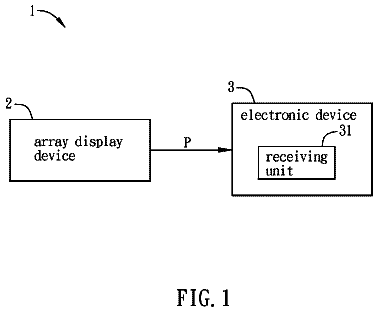
A wireless power transmission system includes an electronic device and an array display device.
US 9,793,773 B2 · Assignee: HONDA MOTOR CO., LTD. · Inventors: Iki; Tomotaka
Sheet 1 of 22 from the published document. All sheets in the USPTO PDF
One embodiment provides a stator of an electric rotary machine, including: a stator core having plural slots; a segmented coil of plural phases; and plural base plates laminated at each end of the stator core in an axial direction. While the stator core and plural coil bars of the segmented coil form a stator core assembly, and the plural base plates and plural end coil connections of the segmented coil form plural base plate assemblies. The stator is configured by the stator core assembly and the plural base plate assemblies laminated at each end of the stator core assembly.
JP-2013-027172-A discloses a technique for a stator of a motor in which a segmented coil is used not only to suppress the height of a spanning portion while ensuring a high space factor but also to simplify the fabrication process. Specifically, as shown in FIG. 22 , a stator 100 of an electric rotary machine includes a stator core assembly 101 which includes, in turn, a stator core 103 and plural coil bars 105 which are inserted individually in plural slots 104 in the stator core 103 and a pair of base plate assemblies 102 which include plural base plates 106 and plural end coil connections 107 which are individually disposed in the base plates 106 to form spanning portions to connect coil bars 105 of the same phase together. The pair of base plate assemblies 102 are disposed at axial ends of the stator core assembly 101 . In the field of electric rotary machines, it is general practice
1 of 22 drawing sheets so far from the published document, cropped to the drawing. Every sheet is in the USPTO PDF.
What the patent claimed, word for word. All of it is now free to use.
This application claims priority from Japanese Patent Application No. 2013-091302 filed on Apr. 24, 2013, the entire contents of which are incorporated herein by reference.
The embodiments described herein relate generally to a stator of an electric rotary machine which is installed in an electric vehicle, a hybrid vehicle or the like and a fabrication method therefor.
JP-2013-027172-A discloses a technique for a stator of a motor in which a segmented coil is used not only to suppress the height of a spanning portion while ensuring a high space factor but also to simplify the fabrication process. Specifically, as shown in FIG. 22 , a stator 100 of an electric rotary machine includes a stator core assembly 101 which includes, in turn, a stator core 103 and plural coil bars 105 which are inserted individually in plural slots 104 in the stator core 103 and a pair of base plate assemblies 102 which include plural base plates 106 and plural end coil connections 107 which are individually disposed in the base plates 106 to form spanning portions to connect coil bars 105 of the same phase together. The pair of base plate assemblies 102 are disposed at axial ends of the stator core assembly 101 .
In the field of electric rotary machines, it is general practice to increase the numbers of turns of coil or pole pairs as a specification of an electric rotary machine changes. However, in the stator 100 of the electric rotary machine of JP-2013-027172-A, when the numbers of turns of coil or pole pairs are attempted to be increased, the number of end coil connections 107 needs to be increased accordingly. Thus, it is necessary that the end coil connections 107 are made thinner or an outside diameter of the stator 100 is increased. When the number of end coil connections 107 is increased by making them thinner, since it is necessary to increase the number of insulation layers in association with the increase in the number of end coil connections 107 , the space factor may be reduced. In addition, it may also affect the joining of the end coil connections 107 with the coil bars 105 , which is not preferable from the viewpoint of fabrication of the stator. On the other hand, when the outside diameter of the stator 100 is increased, the installation properties of the electric rotary machine may be deteriorated, and the electric rotary machine may not satisfy the recent demand for reduction in size. Thus, there still remains room for improvement in the stator 100 .
One object of the embodiments is to provide a stator of an electric rotary machine which can increase the numbers of turns of coil or pole pairs while suppressing the increase in outside diameter of the stator or height in a spanning portion between coils and which can easily be fabricated, and a fabrication method therefor.
The embodiments provides following Aspects 1 to 8.
1. A stator (e.g., stators 10 , 10 A in embodiment) of an electric rotary machine, including:
a stator core (e.g., a stator core 21 in embodiment) having plural slots (e.g., slots 23 in embodiment);
a segmented coil (e.g., a coil 60 in embodiment) of plural phases; and
plural base plates (e.g., first base plates 31 L, 31 R, second base plates 41 L, 41 R in embodiment) laminated at each end of the stator core in an axial direction,
wherein the segmented coil includes plural coil bars (e.g., first coil bars 26 , second coil bars 27 in embodiment) which are individually inserted in the plural slots in the stator core and which extend substantially straight and plural end coil connections (e.g., plural end coil connections 50 in embodiment) which are disposed on each of the base plates to form spanning portions to connect the coil bars of the same phase together,
wherein the stator core and the plural coil bars form a stator core assembly (e.g., a stator core assembly 20 in embodiment),
wherein the plural base plates and the plural end coil connections form plural base plate assemblies (e.g., first base plate assemblies 30 L, 30 R, second base plate assemblies 40 L, 40 R in embodiment), and
wherein the stator is configured by the stator core assembly and the plural base plate assemblies laminated at each end of the stator core assembly.
2. The stator of Aspect 1,
wherein at least a first and second coil bars (e.g., a first coil bar 26 and a second coil bar 27 in embodiment) are inserted in each of the slots in the stator core so as to be aligned radially with each other, and
wherein the first and second coil bars are connected individually to the end coil connections of the different base plate assemblies.
3. The stator of Aspect 1 or 2,
wherein the coil bars which are inserted in each of the slots in the stator core include a first coil bar which is inserted radially outwards and a second coil bar which is inserted radially inwards,
wherein the first coil bar is connected to the end coil connection on a first base plate assembly (e.g., the first base plate assemblies 30 L, 30 R in embodiment) which is disposed axially outwards of the stator core assembly, and
wherein the second coil bar is connected to the end coil connection on a second base plate assembly (e.g., the second base plate assemblies 40 L, 40 R in embodiment) which is disposed axially outwards of the first base plate assembly.
4. The stator of Aspect 3,
wherein the second coil bar has an axial length which is longer than an axial length of the first coil bar.
5. The stator of Aspect 3 or 4,
wherein an outside diameter (e.g., an outside diameter D2 in embodiment) of the second base plate assembly is smaller than an outside diameter (e.g., an outside diameter D1 in embodiment) of the first base plate assembly.
6. The stator of any one of Aspects 3 to 5,
wherein an insulating member (e.g., an insulating sheet element 66 in embodiment) is interposed between the first base plate assembly and the second base plate assembly, the insulating member being locking the first base plate assembly and the second base plate assembly together and electrically insulating the end coil connections on the first base plate assembly and the end coil connections on the second base plate assembly from each other.
7. A fabrication method for a stator of an electric rotary machine including: a stator core having plural slots; a segmented coil of plural phases; and plural base plates laminated at each end of the stator core in an axial direction, wherein the segmented coil includes plural coil bars which are individually inserted in the plural slots in the stator core and which extend substantially straight and plural end coil connections which are disposed on each of the base plates to form spanning portions to connect the coil bars of the same phase together, the method including:
inserting the plural coil bars in the individual slots in the stator core to form a stator assembly;
disposing the plural end coil connections individually in the base plates to form plural base plate assemblies; and
laminating the plural base plate assemblies to each side of the stator core assembly while interposing an insulating member therebetween to assemble them.
8. The method of Aspect 7,
wherein the plural base plate assemblies are laminated together with another insulating member interposed therebetween.
According to Aspect 1, the number of turns of coil or pole pairs can be increased while suppressing the increase in outside diameter of the stator or height of the spanning portion of the coil and to execute the easy assemblage of the constituent components.
According to Aspect 2, the increase in height of the spanning portion of the coil can be suppressed while increasing the number of windings in the same slot.
According to Aspect 3, the second coil bar and the second base plate assembly can be easily assembled without being interrupted by the first coil bar and the first base plate assembly.
According to Aspect 4, the second coil bar projects axially further than the first base plate assembly, and the second coil bar and the second base plate assembly can be easily assembled after the first coil bar and the first base plate assembly are connected together.
According to Aspect 5, the volume of the stator becomes smaller, thereby enhancing the installation properties of the stator.
According to Aspect 6, the end coil connections on the first base plate assembly and the end coil connections on the second base plate assembly can be isolated electrically from each other.
According to Aspect 7, even though the number of turns of coil or pole pairs is increased, the stator can be formed without increasing the outside diameter of the stator or height in the spanning portion of the coil.
According to Aspect 8, the end coil connections of the plural base plate assemblies can be electrically isolated from each other.
FIG. 1 is a perspective view of a stator of an electric rotary machine according to a first embodiment.
FIG. 2 is an exploded perspective view of the stator shown in FIG. 1 .
FIG. 3 is a partially enlarged side view of a stator core assembly.
FIG. 4 is a perspective view of a coil bar assembly.
FIG. 5 is a vertical sectional view of the stator shown in FIG. 1 .
FIG. 6 is a perspective view showing part of the stator shown in FIG. 1 which is sectioned vertically.
FIG. 7 is a plan view of a first base plate.
FIG. 8 is a plan view of a second base plate.
FIG. 9A is a plan view of a main part of a first base plate assembly with the first base plate omitted, and FIG. 9B is a plan view of a main part of a second base plate assembly with the second base plate omitted.
FIG. 10 is a perspective view of a segmented coil of plural phases.
FIG. 11 is a rolled-out view of the stator which shows an example where coils are connected in series.
FIG. 12 is a rolled-out view of the stator which shows another example where coils are connected in series.
FIG. 13 is a rolled-out view of the stator which shows an example where coils are connected in parallel.
FIG. 14 is a rolled-out view of the stator which shows another example where coils are connected in parallel.
FIG. 15A is a schematic view which depicts a height of a spanning portion of a conventional base plate assembly, and FIG. 15B shows a schematic view which depicts a height of a spanning portion of the base plate assembly.
FIG. 16 is a diagram which explains a calculation of a spanning height of an end coil connection.
FIG. 17 is a side view of a stator of a second embodiment with base plates omitted.
FIG. 18 is a perspective view of the stator shown in FIG. 17 with the base plates omitted.
FIG. 19 is a perspective view of part of the stator shown in FIG. 17 which is taken along the line XIX-XIX therein.
FIG. 20 is a perspective view of a main part of the stator shown in FIG. 17 which shows part of coils thereof.
FIG. 21 is a perspective view of a main part of the stator shown in FIG. 17 which shows coils thereof
FIG. 22 is a vertical sectional view of a main part of a conventional stator. DETAILED DESCRIPTION First Embodiment
A stator of an electric rotary machine according to a first embodiment will be described in detail based on the accompanying drawings. The drawings should be seen in directions in which given reference numerals look normally.
As shown in FIGS. 1, 2, 5 and 6 , a stator 10 of an electric rotary machine of this embodiment is a six-pair, eight-turn double-slot type stator and includes a stator core assembly 20 , a pair of first base plate assemblies 30 L, 30 R, and a pair of second base plate assemblies 40 L, 40 R. In this stator 10 , the first and second base plate assemblies 30 L, 30 R, 40 L, 40 R are assembled to both ends of the stator core assembly 20 so as to be laminated together in an axial direction. Specifically, the pair of first base plate assemblies 30 L, 30 R are disposed individually at the axial ends of the stator core assembly 20 , and the pair of second base plate assemblies 40 L, 40 R are disposed at axial outer sides of the first base plate assemblies 30 L, 30 R, respectively.
Annular insulating sheet elements 66 of silicone, for example, are disposed individually, between the stator core assembly 20 and the first base plate assemblies 30 L, 30 R and between the first base plate assemblies 30 L, 30 R and the second base plate assemblies 40 L, 40 R, so that the stator core assembly 20 and the first base plate assemblies 30 L, 30 R and the first base plate assemblies 30 L, 30 R and the second base plate assemblies 40 L, 40 R are electrically insulated from each other by the annular insulating sheet elements 66 .
As shown in FIGS. 3 and 4 , the stator core assembly 20 includes a stator core 21 and plural ( 72 in this embodiment shown in the figures) coil bar assemblies 25 .
The stator core 21 is formed of a lamination of plural pressed-out silicon steel plates and includes 72 teeth 22 and 72 slots 23 which are defined between adjacent teeth 22 , 22 on a radially inner side thereof. The slots 23 are formed so as to penetrate the stator core 21 axially and are each formed substantially into an elliptic shape which is long in a radial direction of the stator core 21 as viewed from an axial direction of the stator core 21 , with opening portions 24 opened to an inner circumferential surface of the stator core 21 .
As shown in FIG. 4 , the coil bar assembly 25 includes a first coil bar 26 which includes, in turn, a first radially outer coil bar 26 o and a first radially inner coil bar 26 i and a second coil bar 27 which includes, in turn, a second radially outer coil bar 27 o and a second radially inner coil bar 27 i . The first radially outer coil bar 26 o , the first radially inner coil bar 26 i , the second radially outer coil bar 27 o and the second radially inner coil bar 27 i are disposed so as to be aligned into a straight line in that order and are then covered therearound by an insulating material 28 such as an injection molded resin, excluding ends thereof so as to be integrated into a single element. The second radially outer coil bar 27 o and the second radially inner coil bar 27 i are axially longer than the first radially outer coil bar 26 o and the first radially inner coil bar 26 i.
The first radially outer coil bar 26 o and the first radially inner coil bar 26 i have the same shape and the same length and are set to a length which is substantially the same as a sum of an axial length of the stator core 21 and a total thickness of three end coil connections 50 , which will be described later. A small-diameter portion 26 a having a length which is substantially the same as the thickness of the end coil connection 50 is formed at each end of the first radially outer and inner coil bars. The first radially outer coil bar 26 o and the first radially inner coil bar 26 i are disposed in parallel by being offset axially from each other by an amount equal to the thickness of the end coil connection 50 .
The second radially outer coil bar 27 o and the second radially inner coil bar 27 i have the same shape and the same length and are set to a length which is substantially the same as a sum of the axial length of the stator core 21 and a total thickness of seven end coil connections 50 . A small-diameter portion 27 a having a length which is substantially the same as the thickness of the end coil connection 50 is formed at each end of the second radially outer and inner coil bars. The second radially outer coil bar 27 o and the second radially inner coil bar 27 i are disposed in parallel by being offset axially from each other by an amount equal to the thickness of the end coil connection 50 .
As shown in FIG. 3 , the oil bar assemblies 25 are aligned in a circumferential direction of the stator core 21 to be inserted individually in the 72 slots 23 in the stator core 21 so that the first coil bar 26 is disposed radially outwards and the second coil bar 27 is disposed radially inwards in each slot 23 to thereby form the stator core assembly 20 .
As shown in FIGS. 5 and 6 , when the coil bar assembly 25 is inserted in the slot 23 in the stator core 21 , the first radially outer coil bar 26 o is inserted in the slot 23 so that the small-diameter portion 26 a projects from one end face 21 a (a left end face in FIG. 5 ) of the stator core 21 by an amount substantially equal to the thickness of one end coil connection 50 , while the small-end portion 26 a projects from the other end face 21 b (a right end face in FIG. 5 ) by an amount substantially equal to a total thickness of two end coil connections 50 .
The first radially inner coil bar 26 i is inserted in the slot 23 so that the small-diameter portion 26 a projects from the one end face 21 a of the stator core 21 by an amount substantially equal to a total thickness of two end coil connections 50 , while the small-end portion 26 a projects from the other end face 21 b by an amount substantially equal to the thickness of one end coil connection 50 .
The second radially outer coil bar 27 o is inserted in the slot 23 so that the small-diameter portion 27 a projects from the one end face 21 a of the stator core 21 by an amount substantially equal to a total thickness of three end coil connections 50 , while the small-end portion 27 a projects from the other end face 21 b by an amount substantially equal to a total thickness of four end coil connections 50 .
The second radially inner coil bar 27 i is inserted in the slot 23 so that the small-diameter portion 27 a projects from the one end face 21 a of the stator core 21 by an amount substantially equal to a total thickness of four end coil connections 50 , while the small-end portion 27 a projects from the other end face 21 b by an amount substantially equal to a total thickness of three end coil connections 50 .
In this way, the insulating material 28 which covers the first and second coil bars 26 , 27 is interposed between both the coil bars 26 , 27 and the slot 23 in the stator core 21 , whereby the electrical insulation between the coil bars and the stator core 21 is ensured thereby. The first coil bar 26 and the second coil bar 27 are covered by the insulating material 28 such that the first coil bar 26 and the second coil bar 27 are offset axially from each other so that the end portions thereof take different axial positions.
The first base plate assemblies 30 L, 30 R include the first base plates 31 L, 31 R and plural end coil connections 50 which are assembled to the first base plates 31 L, 31 R, respectively. The second base plate assemblies 40 L, 40 R include the second base plates 41 L, 41 R and plural end coil connections 50 which are assembled to the second base plates 41 L, 41 R, respectively.
The first and second base plate assemblies 30 R, 40 R are the same as the first and second base plate assemblies 30 L, 40 L in the other configurations than those in which connecting terminal portions, which will be described later, are not provided and in which the shapes of grooves and end coil connections are different. Therefore, in the following description, the first and second base plate assemblies 30 L, 40 L will mainly be described.
As shown in FIGS. 7 and 8 , the first and second base plates 31 L, 41 L are substantially annular members which are formed from a resin having insulating properties (a non-magnetic material) and which have a bore diameter and an outside diameter which are substantially the same as those of the stator core 21 . As shown in respective upper half portions of the figures, deployed portions 31 a , 41 a which extend in a segmental fashion are provided at a radially outer side of the first and second base plates 31 L, 41 L, respectively. Connecting terminal portions are provided on these deployed portions 31 a , 41 a for connection to external equipment or bus bars.
In the first base plate 31 L, 72 first radially outer through holes 32 o and first radially inner through holes 32 i and 72 second radially outer through holes 33 o and second radially inner through holes 33 i are formed on a radially inner side thereof so as to penetrate the first base plate 31 L in positions which correspond to the first radially outer coil bars 26 o and the first radially inner coil bars 26 i of the first coil bars 26 inserted in the slots 23 in the stator core 21 and the second radially outer coil bars 27 o and the second radially inner coil bars 27 i of the second coil bars 27 also inserted in the slots 23 in the stator core 21 .
The first radially outer through holes 32 o , the first radially inner through holes 32 i , the second radially outer through holes 33 o and the second radially inner through holes 33 i are located on the same straight lines L which extend radially from a center O of the first base plate 31 L. Outer circumferential holes 34 o are formed on the straight lines L and on a radially outer side of the first base plate 31 L to thereby establish a communication between an outer surface 37 and an inner surface 38 (refer to FIG. 5 ) of the first base plate 31 L. Six connecting terminal joining holes 34 t are formed in the circumferential position of the first base plate 31 L where the deployed portion 31 a is formed in positions which lie further radially outwards than the outer circumferential holes 34 o so as to be positioned in the deployed portion 31 a.
On the other hand, in the second base plate 41 L, 72 second radially outer through holes 43 o and second radially inner through holes 43 i are formed on a radially inner side thereof so as to penetrate the second base plate 41 L in positions which correspond to the second radially outer coil bars 27 o and the second radially inner coil bars 27 i of the second coil bars 27 which are inserted in the slots 23 in the stator core 21 .
The second radially outer through holes 43 o and the second radially inner through holes 43 i are located on the same straight lines L which extend radially from a center O of the second base plate 41 L. Outer circumferential holes 44 o are formed on the straight lines L and on a radially outer side of the second base plate 41 L to thereby establish a communication between an outer surface 47 and an inner surface 48 (refer to FIG. 5 ) of the second base plate 41 L. Six connecting terminal joining holes 44 t are formed in the circumferential position of the second base plate 41 L where the deployed portion 41 a is formed in positions which lie further radially outwards than the outer circumferential holes 44 o so as to be positioned in the deployed portion 41 a.
Plural ( 72 ) first left side grooves 35 , U-shaped in cross-section and opened to the outer surface 37 , and plural ( 72 ) first right side grooves 36 , U-shaped in cross-section and opened to the inner surface 38 , are formed in the outer surface 37 and the inner surface 38 of the first base plate 31 L, respectively, so as to be close to one another along involute curves in a circumferential direction of the first base plate 31 . The first left side grooves 35 which lie adjacent to one another and the first right side grooves 36 which lie adjacent to one another are separated individually by walls 31 b which are erected from the first base plate 31 L. The first left-hand side groves 35 and the first right side grooves 36 which are opposite to each other in the axial direction are separated from each other by a bulkhead 31 c . Thus, the first left side grooves 35 and the first right side grooves 36 are individually electrically insulated (refer to FIG. 5 ).
Plural ( 72 ) second left side grooves 45 , U-shaped in cross-section and opened to the outer surface 47 , and plural ( 72 ) second right side grooves 46 , U-shaped in cross-section and opened to the inner surface 48 , are formed in the outer surface 47 and the inner surface 48 of the second base plate 41 L, respectively, so as to be close to one another along involute curves in a circumferential direction of the second base plate 41 L. The second left side grooves 45 which lie adjacent to one another and the second right side grooves 46 which lie adjacent to one another are separated individually by walls 41 b which are erected from the second base plate 41 L. The second left-hand side groves 45 and the second right side grooves 46 which are opposite to each other in the axial direction are separated from each other by a bulkhead 41 c . Thus, the second left side grooves 45 and the second right side grooves 46 are individually electrically insulated (refer to FIG. 5 ).
The first and second base plates 31 L, 41 L are each set to an axial width which is substantially equal to a sum of respective depths of the left side groove 35 / 45 and the right side groove 36 / 46 which correspond to the thicknesses of the end coil connections 50 (a first left-hand side end coil connection 51 and a first right-hand side end coil connection 52 or a second left-hand side end coil connection 56 and a second right-hand side end coil connection 57 , which will be described later) and a thickness of the bulkhead 31 c / 41 c.
The first and second left side grooves 35 , 45 of the first and second base plates 31 L, 41 L are formed curvilinearly along the involute curves, as indicated by solid lines in FIGS. 7 and 8 , so as to connect together the first and second radially inner through holes 32 i , 43 i and the outer circumferential holes 34 o , 44 o which are formed on the straight lines L which pass through the first radially inner through holes 32 i , 43 i which are five holes apart in a clockwise direction from the first and second radially inner through holes 32 i , 43 i.
In the plural first and second left side grooves 35 , 45 , six first left side grooves 35 a and six second left side grooves 45 a which extend towards the deployed portions 31 a , 41 a extend along the involute curves to reach the straight lines L which pass through the first and second radially inner through holes 32 i , 43 i which are five holes apart in the clockwise direction from the first and second radially inner through holes 32 i , 43 i and thereafter connect to the connecting terminal joining holes 34 t , 44 t which are situated slightly further radially outwards than the outer circumferential holes 34 o , 44 o.
The first left side grooves 35 , 35 a and the second left side grooves 45 , 45 a are formed so as to extend radially while bending so as to avoid the first and second radially outer through holes 32 o , 43 o and thereafter to extend along the involute curves. However, since the radial positions of the first radially inner through hole 32 i and the second radially inner through hole 43 i are different, portions of the second left side grooves 45 , 45 a which extend radially are formed longer than those of the first left side grooves 35 , 35 a.
The first and second right side grooves 36 , 46 of the first and second base plates 31 L, 41 L are formed curvilinearly along the involute curves, as indicated by broken lines in FIGS. 7 and 8 , so as to connect together the first and second radially outer through holes 32 o , 43 o and the outer circumferential holes 34 o , 44 o which are formed on the straight lines L which pass through the first and second radially outer through holes 32 o , 43 o which are five holes apart in a counterclockwise direction from the first and second radially outer through holes 32 o , 43 o.
In the plural first and second right side grooves 36 , 46 , six first right side grooves 36 a and six second right side grooves 46 a which extend towards the deployed portions 31 a , 41 a extend along the involute curves to reach the straight lines L which pass through the first and second radially outer through holes 32 o , 43 o which are five holes apart in the counterclockwise direction from the first and second radially outer through holes 32 o , 42 o and thereafter connect to the connecting terminal joining holes 34 t , 44 t.
Although the first right side grooves 36 , 36 a are formed curvilinearly so as to extend directly from the first radially outer through holes 32 o along the involute curves, the second right side grooves 46 , 46 a are formed so as to extend radially along the straight lines L which pass through the second radially outer through holes 43 o to thereafter bend along the involute curves.
Consequently, as shown in FIGS. 7 and 8 , the first and second radially outer through holes 32 o , 43 o and the first and second radially inner through holes 32 i , 43 i which are situated 10 holes apart from each other in the clockwise direction (or the counterclockwise direction) continue to each other via the first and second left side grooves 35 , 45 , the outer circumferential holes 34 o , 44 o , and the first and second right side grooves 36 , 46 .
In the base plate assemblies 30 R, 40 R, respective first and second left side grooves 35 , 45 of the first and second base plates 31 R, 41 R are opened to inner surfaces 38 , 48 , and respective first and second right side grooves 36 , 46 are opened to outer surfaces 37 , 47 . The first left side grooves 35 of the base plates 31 L, 31 R have the same shape, and the first right side grooves 36 of the first base plates 31 L, 31 R also have the same shape. The second left side grooves 45 of the second base plates 41 L, 41 R have the same shape, and the second right side grooves 46 of the second base plates 41 L, 41 R also have the same shape.
The end coil connections 50 are each formed of a conductive material such as copper into something like a plate. As shown in FIGS. 5 and 9 , in the first base plate assembly 30 L, the end coil connections 50 include first left-hand side end coil connections 51 , 51 a which are inserted in the first left side grooves 35 , 35 a , respectively, and first right-hand side end coil connections 52 , 52 a which are inserted in the first right side grooves 36 , 36 a , respectively. In the second base plate 40 L, the end coil connections 50 include second left-hand side end coil connections 56 , 56 a which are inserted in the second left side grooves 45 , 45 a , respectively, and second right-hand side end coil connections 57 , 57 a which are inserted in the second right side grooves 46 , 46 a , respectively.
As indicated by solid lines in FIG. 9A , the first left-hand side end coil connections 51 have the same shape as that of the first left side grooves 35 , and connecting holes 53 a , 53 b are formed in both end portions thereof. The first left-hand side end coil connections 51 a have the same shape as that of the first left-hand side groves 35 a , and a connecting hole 53 a and a connecting terminal hole 53 c are formed in both end portions thereof.
As indicated by broken lines in FIG. 9A , the first right-hand side end coil connections 52 have the same shape as that of the first right side grooves 36 , and connecting holes 54 a , 54 b are formed in both end portions thereof. The first right-hand side end coil connections 52 a have the same shape as that of the first right-hand side groves 36 a , and a connecting hole 54 a and a connecting terminal hole 54 c are formed in both end portions thereof.
Similarly, as indicated by solid lines in FIG. 9B , the second left-hand side end coil connections 56 have the same shape as that of the second left side grooves 45 , and connecting holes 58 a , 58 b are formed in both end portions thereof. The second left-hand side end coil connections 56 a have the same shape as that of the second left-hand side groves 45 a , and a connecting hole 58 a and a connecting terminal hole 58 c are formed in both end portions thereof.
As indicated by broken lines in FIG. 9B , the second right-hand side end coil connections 57 have the same shape as that of the second right side grooves 46 , and connecting holes 59 a , 59 b are formed in both end portions thereof. The second right-hand side end coil connections 57 a have the same shape as that of the second right-hand side groves 46 a , and a connecting hole 59 a and a connecting terminal hole 59 c are formed in both end portions thereof
These connecting holes 53 a , 54 a , 58 a , 59 a have diameters which are substantially equal to the small-diameter portion 26 a of the coil bars 26 i , 26 o , 27 i , 27 o , respectively, and the connecting holes 53 b , 54 b , 58 b , 59 b have diameters which are substantially equal to that of a connecting pin 55 .
Then, the first left-hand side end coil connections 51 , 51 a are inserted in the first left side grooves 35 , 35 a , respectively, and the first right-hand side end coil connections 52 , 52 a are inserted in the first right side grooves 36 , 36 a , respectively. Connecting pins 55 which are each made of a conductive material such as copper, aluminum or the like are inserted into the connecting holes 54 b to thereby connect electrically the first left-hand side end coil connections 51 and the first right-hand end coil connections 52 together.
Similarly, the second left-hand side end coil connections 56 , 56 a are inserted in the second left side grooves 45 , 45 a , respectively, and the second right-hand side end coil connections 57 , 57 a are inserted in the second right side grooves 46 , 46 a , respectively. And, connecting pins 55 are also inserted into the connecting holes 59 b to thereby connect electrically the second left-hand side end coil connections 56 and the second right-hand end coil connections 57 together.
Thus, the first base plate assemblies 30 L, 30 R are formed such that the connecting hole 53 a in the first left-hand side end coil connection 51 and the connecting hole 54 a in the first right hand-side end coil connection 52 which are situated 10 holes apart from each other in the clockwise (or counterclockwise) direction are electrically connected together via the first left-hand side end coil connection 51 , the connecting pin 55 and the first right-hand side end coil connection 52 .
The second base plate assemblies 40 L, 40 R are formed such that the connecting hole 58 a in the second left-hand side end coil connection 56 and the connecting hole 59 a in the second right hand-side end coil connection 57 which are situated 10 holes apart from each other in the clockwise (or counterclockwise) direction are electrically connected together via the second left-hand side end coil connection 56 , the connecting pin 55 and the second right-hand side end coil connection 57 .
In the stator core assembly 20 , the first base plate assemblies 30 L, 30 R and the second base plate assemblies 40 L, 40 R which are assembled individually in the ways described above, as shown in FIGS. 2, 5 and 6 , the first base plate assemblies 30 L, 30 R and the second base plate assemblies 40 L, 40 R are assembled individually to the axial ends of the stator core assembly 20 so as to be laminated together, whereby the stator 10 is formed.
Thus, when the stator 10 is so formed, as shown in FIGS. 5 and 6 , in the first base plate assembly 30 L which is disposed at one end face 21 a (a left-hand side in the figures) of the stator core 21 , the second radially outer coil bar 27 o and the second radially inner coil bar 27 i are inserted into the second radially outer through hole 33 o and the second radially inner through hole 33 i (refer to FIG. 7 ) of the first base plate 31 L, respectively, and the small-diameter portion 26 a of the first radially outer coil bar 26 o is inserted into the connecting hole 54 a of the first right-hand side end coil connection 52 / 52 a and the small-diameter portion 26 a of the first radially inner coil bar 26 i is inserted into the connecting hole 53 a of the first left-hand side end coil connection 51 / 51 a . Thereafter, the small-diameter end portions 26 a are joined to the corresponding holes through pressing or welding. The connecting hole 53 b of the first left-hand side end coil connection 51 and the connecting hole 54 b of the first right-hand side end coil connection 52 are joined together by the connecting pin 55 . Namely, the first left-hand side end coil connection 51 / 51 a and the first right-hand side end coil connection 52 / 52 a connect the coil bars 26 of the same phase (for example, a U phase) to thereby configure the end coil connections 50 functioning as spanning portions of a coil 60 .
Similarly in the base plate assembly 30 R which is disposed at the other end face 21 b (a right-hand side in the figures) of the stator core 21 , the second radially outer coil bar 27 o and the second radially inner coil bar 27 i are inserted into the second radially outer through hole 33 o and the second radially inner through hole 33 i of the base plate 31 R, respectively, and the small-diameter portion 26 a of the first radially outer coil bar 26 o is inserted into the connecting hole 54 a of the first right-hand side end coil connection 52 / 52 a and the small-diameter portion 26 a of the first radially inner coil bar 26 i is inserted into the connecting hole 53 a of the first left-hand side end coil connection 51 . Thereafter, the small-diameter end portions are joined to the corresponding holes. The connecting hole 53 b of the first left-hand side end coil connection 51 and the connecting hole 54 b of the first right-hand side end coil connection 52 are joined together by the connecting pin 55 . Namely, the first left-hand side end coil connection 51 and the first right-hand side end coil connection 52 connect the coil bars 26 of the same phase (for example, a U phase) to thereby configure the end coil connections 50 functioning as spanning portions of the coil 60 .
Consequently, with respect to the first coil bar 26 which is disposed in one slot 23 , the first right-hand side end coil connection 52 which is connected at the one end 21 a (the left-hand side in the figures) of the first radially outer coil bar 26 o extends radially outwards and in the counterclockwise direction to be connected to the first left-hand side end coil connection 51 of the same phase, while the first right-hand side end coil connection 52 which is connected at the other end 21 b (the right-hand side in the figures) of the first radially outer coil bar 26 o extends radially outwards and in the clockwise direction to be connected to the first left-hand side end coil connection 51 of the same phase. The first left-hand side end coil connection 51 which is connected at the one end 21 a (the left-hand side in the figures) of the first radially inner coil bar 26 i extends radially outwards and in the clockwise direction to be connected to the first right-hand side end coil connection 52 of the same phase, while the first left-hand side end coil connection 51 which is connected at the other end 21 b (the right-hand side in the figures) of the first radially inner coil bar 26 i extends radially outwards and in the counterclockwise direction to be connected to the first right-hand side end coil connection 52 of the same phase.
As shown in FIGS. 5 and 6 , also, in the base plate assembly 40 L which is disposed at one end face (a left-hand side in the figures) of the base plate assembly 30 L, the small-diameter end portion 27 a of the second radially outer coil bar 27 o is inserted into the connecting hole 59 a of the second right-hand side end coil connection 57 / 57 a and the small-diameter portion 27 a of the second radially inner coil bar 27 i is inserted into the connecting hole 58 a of the second left-hand side end coil connection 56 / 56 a , whereafter the small-diameter end portions are joined to the corresponding holes. The connecting hole 58 b of the second left-hand side end coil connection 56 and the connecting hole 59 b of the second right-hand side end coil connection 57 are joined together by the connecting pin 55 . Namely, the second left-hand side end coil connection 56 / 56 a and the second right-hand side end coil connection 57 / 57 a connect the coil bars 27 of the same phase (for example, a U phase) together to thereby configure the end coil connections 50 functioning as spanning portions of the coil 60 .
The description continues in the full USPTO document.
About 7,502 words. The USPTO PDF has it with every drawing.
Fees are due 3.5, 7.5 and 11.5 years after grant. This patent expired on October 17, 2025, so the fee marked "not paid" was the one that went unpaid.
STATOR OF ELECTRIC ROTARY MACHINE AND FABRICATION METHOD THEREFOR
Filed Apr 2014 · published Oct 2014Stator of electric rotary machine and fabrication method therefor
Filed Apr 2014 · granted Oct 2017Earlier publications, parents and continuations. None of them can still be enforced, or this patent would not be listed.
Prior art cited by the examiner or applicant. Useful when you check your own idea for novelty.
Everything on this page comes from the documents linked above.


