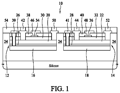
Background
In power semiconductor devices, for example, IGFETs (insulated gate field effect transistors) a load current typically flows in a vertical direction between two load electrodes formed at opposite sides of a semiconductor die that includes a weakly doped drift layer. A dopant concentration in the drift layer results from a tradeoff between blocking capability and on-state resistance of the semiconductor device. Field plate structures extending from a front side into the semiconductor die deplete a portion of the drift layer in the blocking mode such that the dopant concentration in the drift layer can be increased without adverse impact on the blocking capability. Shrinking stripe-shaped field plate structures to needle-shaped field plate structures increases an active transistor area and allows the gate structure to form a grid with larger channel width compared to stripe-shaped gate structures.
It is desirable to further improve the performance of power semiconductor devices.
Summary
According to an embodiment a semiconductor device includes a drift region that extends from a first surface into a semiconductor portion. A body region between two portions of the drift region forms a first pn junction with the drift region. A source region between two portions of the body region forms a second pn junction with the body region. The first and second pn junctions include sections perpendicular to the first surface. Gate structures including gate electrodes extend from the first surface into the body regions. Field plate structures including field electrodes separated from the gate electrodes extend from the first surface into the drift region. A gate shielding structure in a vertical projection of the gate structures is configured to reduce a capacitive coupling between the gate structures and a backplate electrode directly adjoining a second surface of the semiconductor portion opposite to the first surface.
According to another embodiment a method of forming a semiconductor device includes forming a drift region extending from a main surface into a base substrate. A body region is formed between two portions of the drift region, wherein the body region forms a first pn junction with the drift region. A source region is formed between two portions of the body region, wherein the source region forms a second pn junction with the body region. The first and second pn junctions include sections perpendicular to the main surface. Gate structures are formed that extend from the main surface into the body regions and that include a gate electrode. Field plate structures are formed that extend from the main surface into the drift region and that include a field electrode separated from the gate electrode. A gate shielding structure is formed in a vertical projection of the gate structures. The gate shielding structure is configured to reduce a capacitive coupling between the gate structures and a backplate electrode that directly adjoins a supporting surface opposite to the main surface.
Those skilled in the art will recognize additional features and advantages upon reading the following detailed description and on viewing the accompanying drawings.
Brief description of the drawings
The accompanying drawings are included to provide a further understanding of the invention and are incorporated in and constitute a part of this specification. The drawings illustrate the embodiments of the present invention and together with the description serve to explain principles of the invention. Other embodiments of the invention and intended advantages will be readily appreciated as they become better understood by reference to the following detailed description.
FIG. 1A is a schematic horizontal cross-sectional view of a portion of a semiconductor device according to embodiments referring to a vertical pn junction between a body region and a drift region and with a gate shielding structure between gate structures and a backplate electrode.
FIG. 1B is a schematic vertical cross-sectional view of the semiconductor device portion of FIG. 1A along line B-B through a contact structure.
FIG. 1C is a schematic vertical cross-sectional view of the semiconductor device portion of FIG. 1A along line C-C through gate and field plate structures.
FIG. 2A is a schematic cross-sectional view of a portion of a semiconductor device according to an embodiment including a dielectric separation layer between a drift region and a backplate electrode.
FIG. 2B is a schematic vertical cross-sectional view of the semiconductor device portion of FIG. 2A along line B-B through a contact structure.
FIG. 2C is a schematic vertical cross-sectional view of the semiconductor device portion of FIG. 2A along line C-C through gate and field plate structures.
FIG. 3A is a schematic horizontal cross-sectional view of a portion of a semiconductor device according to an embodiment including vertical metal drain conductors.
FIG. 3B is a schematic vertical cross-sectional view of the semiconductor device portion of FIG. 3A along line P-P through a contact structure.
FIG. 3C is a schematic vertical cross-sectional view of the semiconductor device portion of FIG. 3A along line C-C through gate and field plate structures.
FIG. 4A is a schematic horizontal cross-sectional view of a portion of a semiconductor device according to an embodiment including a horizontal homojunction between a drift region and a base portion of a drain structure.
FIG. 4B is a schematic vertical cross-sectional view of the semiconductor device portion of FIG. 4A along line B-B through a contact structure.
FIG. 4C is a schematic vertical cross-sectional view of the semiconductor device portion of FIG. 4A along line C-C through gate and field plate structures.
FIG. 5A is a schematic horizontal cross-sectional view of a portion of a semiconductor device according to an embodiment including an U-shaped field plate structure and a gate structure formed between the legs of the U-shaped field plate structure.
FIG. 5B is a schematic vertical cross-sectional view of the semiconductor device portion of FIG. 5A along line B-B through a contact structure.
FIG. 5C is a schematic vertical cross-sectional view of the semiconductor device portion of FIG. 5A along line C-C through gate and field plate structures.
FIG. 6A is a schematic vertical cross-sectional view of a portion of a semiconductor device according to an embodiment including a gate shielding dielectric.
FIG. 6B is a schematic vertical cross-sectional view of a portion of a semiconductor device according to an embodiment including a gate shielding zone.
FIG. 7 is a schematic horizontal cross-sectional view of a portion of a semiconductor device in accordance with an embodiment including a termination field plate structure.
FIG. 8 is a schematic vertical cross-sectional view of a portion of a semiconductor device in accordance with an embodiment including a field stop region.
FIG. 9A is a schematic horizontal cross-sectional view of a portion of a semiconductor device according to an embodiment including cross-shaped contact structures directly adjoining to both source regions and body contact zones.
FIG. 9B is a schematic horizontal cross-sectional view of a portion of a semiconductor device according to another embodiment including rectangular contact structures directly adjoining to both source regions and body contact zones.
FIG. 9C is a schematic horizontal cross-sectional view of a portion of a semiconductor device according to an embodiment including rows of drain conductors.
FIG. 9D is a schematic vertical cross-sectional view of a portion of a semiconductor device according to another embodiment including close-to-surface body contact zones.
FIG. 10 is a schematic vertical cross-sectional view of a portion of a semiconductor device according to an embodiment including a body contact zone in a vertical projection of contact structures.
FIG. 11A is a schematic horizontal cross-sectional view of a portion of a semiconductor substrate for illustrating a method of manufacturing a semiconductor device according to an embodiment that includes growing by epitaxy a drift region in epitaxy trenches, after forming the epitaxy trenches in the semiconductor substrate.
FIG. 11B is a schematic vertical cross-sectional view of the semiconductor substrate portion of FIG. 11A along line B-B.
FIG. 12A is a schematic plan view of the semiconductor substrate portion of FIG. 11A , after forming precursor drift regions above a dielectric separation structure.
FIG. 12B is a schematic vertical cross-sectional view of the semiconductor substrate portion of FIG. 12A along line B-B.
FIG. 13A is a schematic plan view of the semiconductor substrate portion of FIG. 12A , after forming precursor body regions on sidewalls of the precursor drift regions and above the dielectric separation structure.
FIG. 13B is a schematic vertical cross-sectional view of the semiconductor substrate portion of FIG. 13A along line B-B.
FIG. 14A is a schematic plan view of the semiconductor substrate portion of FIG. 13A , after planarizing the precursor drift regions, the precursor body regions and precursor source regions formed along sidewalls of the precursor body regions.
FIG. 14B is a schematic vertical cross-sectional view of the semiconductor substrate portion of FIG. 14A along line B-B.
FIG. 15A is a schematic plan view of the semiconductor substrate portion of FIG. 14A , after forming field plate structures.
FIG. 15B is a schematic vertical cross-sectional view through the semiconductor substrate portion of FIG. 15A along line B-B along a horizontal longitudinal center axis of a pair of symmetric field plate structures.
FIG. 16A is a schematic plan view of the semiconductor substrate portion of FIG. 15A , after forming gate structures.
FIG. 16B is a schematic vertical cross-sectional view through the semiconductor substrate portion of FIG. 16A along line B-B along a horizontal longitudinal center axis of a pair of symmetric field plate structures.
FIG. 17A is a schematic plan view of the semiconductor substrate portion of FIG. 16A , after forming contact structures extending into the source and body regions.
FIG. 17B is a schematic vertical cross-sectional view of the semiconductor substrate portion of FIG. 17A along line B-B through a contact structure.
FIG. 18A is a schematic plan view of a portion of a semiconductor substrate for illustrating a method of manufacturing a semiconductor device according to an embodiment including formation of a source region along a source trench and formation of body contact zones, after forming the source trench.
FIG. 18B is a schematic vertical cross-sectional view of the semiconductor substrate portion of FIG. 18A along line B-B orthogonal to a horizontal longitudinal axis of the source trench.
FIG. 19A is a schematic plan view of the semiconductor substrate portion of FIG. 18A , after forming a body region oriented along the source trench.
FIG. 19E is a schematic vertical cross-sectional view of the semiconductor substrate portion of FIG. 19A along line B-B orthogonal to the horizontal longitudinal axis of the source trench.
FIG. 20A is a schematic plan view of the semiconductor substrate portion of FIG. 19A , after forming a source region.
FIG. 20B is a schematic vertical cross-sectional view of the semiconductor substrate portion of FIG. 20A along line B-B orthogonal to the horizontal longitudinal axis of the source trench.
FIG. 21A is a schematic plan view of the semiconductor substrate portion of FIG. 20A , after filling a remaining opening of the source trench with a first sacrificial material.
FIG. 21B is a schematic vertical cross-sectional view of the semiconductor substrate portion of FIG. 21A along line B-B orthogonal to the horizontal longitudinal axis of the source trench.
FIG. 22A is a schematic plan view of the semiconductor substrate portion of FIG. 21A , after forming gate trenches, field plate trenches and drain contact trenches.
FIG. 22B is a schematic vertical cross-sectional view of the semiconductor substrate portion of FIG. 22A along line B-B along horizontal longitudinal axes of the gate and field plate trenches.
FIG. 22C is a schematic vertical cross-sectional view of the semiconductor substrate portion of FIG. 22A along line C-C through mesa portions of a drift region between neighboring lines of gate and field plate trenches and orthogonal to the horizontal longitudinal axis of the source region.
FIG. 23A is a schematic plan view of the semiconductor substrate portion of FIG. 22A , after filling the gate trenches, the field plate trenches and the drain contact trenches with a second sacrificial material.
FIG. 23B is a schematic vertical cross-sectional view of the semiconductor substrate portion of FIG. 23A along line B-B along horizontal longitudinal axes of the gate and field plate trenches filled with the second sacrificial material.
FIG. 23C is a schematic vertical cross-sectional view of the semiconductor substrate portion of FIG. 23A along line C-C through the mesa portions of the drift region.
FIG. 24A is a schematic plan view of the semiconductor substrate portion of FIG. 23A , after removing the second sacrificial material from the field plate trenches.
FIG. 24B is a schematic vertical cross-sectional view of the semiconductor substrate portion of FIG. 24A along line B-B along horizontal longitudinal axes of the field plate trenches.
FIG. 25A is a schematic plan view of the semiconductor substrate portion of FIG. 24A , after forming field plate structures in the field plate trenches.
FIG. 25B is a schematic vertical cross-sectional view of the semiconductor substrate portion of FIG. 25A along line B-B along horizontal longitudinal axes of the field plate structures.
FIG. 26A is a schematic plan view of the semiconductor substrate portion of FIG. 25A , after removing the second sacrificial material from the gate trenches and after forming a gate shielding dielectric.
FIG. 26B is a schematic vertical cross-sectional view of the semiconductor substrate portion of FIG. 26A along line B-B along horizontal longitudinal axes of the field plate structures.
FIG. 27A is a schematic plan view of the semiconductor substrate portion of FIG. 26A , after forming gate structures in the gate trenches.
FIG. 27B is a schematic vertical cross-sectional view of the semiconductor substrate portion of FIG. 27A along line B-B along horizontal longitudinal axes of the field plate structures.
FIG. 28A is a schematic plan view of the semiconductor substrate portion of FIG. 27A , after forming source contact trenches.
FIG. 28B is a schematic vertical cross-sectional view of the semiconductor substrate portion of FIG. 28A along line B-B through a source contact trench and orthogonal to a horizontal longitudinal axis of the source region.
FIG. 29A is a schematic plan view of the semiconductor substrate portion of FIG. 28A , after filling the source contact trenches with a third sacrificial material.
FIG. 29B is a schematic vertical cross-sectional view of the semiconductor substrate portion of FIG. 29A along line B-B through a source contact trench and orthogonal to a horizontal longitudinal axis of the source region.
FIG. 30A is a schematic plan view of the semiconductor substrate portion of FIG. 29A , after forming an auxiliary mask with openings exposing the second sacrificial material in the drain contact trenches and the third sacrificial material in the source contact trenches.
FIG. 30B is a schematic vertical cross-sectional view of the semiconductor substrate portion of FIG. 30A along line B-B through a source contact trench and orthogonal to a horizontal longitudinal axis of the source region.
FIG. 31A is a schematic plan view of the semiconductor substrate portion of FIG. 30A , after forming contact structures in the source contact trenches and metal drain conductors in the drain contact trenches.
FIG. 31B is a schematic vertical cross-sectional view of the semiconductor substrate portion of FIG. 31A along line B-B through a source contact trench and orthogonal to a horizontal longitudinal axis of the source region.
FIG. 32A is a schematic plan view of the semiconductor substrate portion of FIG. 31A , after forming load electrodes on opposite sides of the semiconductor substrate.
FIG. 32B is a schematic vertical cross-sectional view of the semiconductor substrate portion of FIG. 32A along line B-B through a source contact trench and orthogonal to a horizontal longitudinal axis of the source region.
FIG. 32C is a schematic vertical cross-sectional view of the semiconductor substrate portion of FIG. 32A along line C-C along a horizontal longitudinal axis of the field plate structures.
FIG. 33A is a schematic plan view of a portion of a semiconductor substrate for illustrating a method of manufacturing a semiconductor device according to an embodiment including formation of body contact zones through sidewalls of deep body contact trenches, after forming the deep body contact trenches.
FIG. 33B is a schematic vertical cross-sectional view of the semiconductor substrate portion of FIG. 33A along line B-B orthogonal to a horizontal longitudinal axis of a body region.
FIG. 34A is a schematic plan view of the semiconductor substrate portion of FIG. 33A , after forming the body contact zones.
FIG. 34B is a schematic vertical cross-sectional view of the semiconductor substrate portion of FIG. 34A along line B-B orthogonal to the horizontal longitudinal axis of the body region.
FIG. 35A is a schematic plan view of a portion of a semiconductor substrate for illustrating a method of manufacturing a semiconductor device according to an embodiment including formation of body contact zones and source zones through sidewalls of deep body contact trenches, after forming the deep body contact trenches.
FIG. 35B is a schematic vertical cross-sectional view of the semiconductor substrate portion of FIG. 35A along line B-B orthogonal to a horizontal longitudinal axis of a body region.
FIG. 36A is a schematic plan view of the semiconductor substrate portion of FIG. 35A , after forming the body contact and source zones.
FIG. 36B is a schematic vertical cross-sectional view of the semiconductor substrate portion of FIG. 36A along line B-B orthogonal to the horizontal longitudinal axis of the body region.
FIG. 37A is a schematic plan view of a portion of a semiconductor substrate for illustrating a method of manufacturing a semiconductor device according to an embodiment including formation of close-to-surface body contact zones, after forming contact structures.
FIG. 37B is a schematic vertical cross-sectional view of the semiconductor substrate portion of FIG. 37A along line B-B orthogonal to a horizontal longitudinal axis of a body region.
FIG. 38A is a schematic plan view of the semiconductor substrate portion of FIG. 37A , after forming the close-to-surface body contact zones.
FIG. 38B is a schematic vertical cross-sectional view of the semiconductor substrate portion of FIG. 38A along line B-B orthogonal to the horizontal longitudinal axis of the body region.
Detailed description
In the following detailed description, reference is made to the accompanying drawings, which form a part hereof and in which are shown by way of illustrations specific embodiments in which the invention may be practiced. It is to be understood that other embodiments may be utilized and structural or logical changes may be made without departing from the scope of the present invention. For example, features illustrated or described for one embodiment can be used on or in conjunction with other embodiments to yield yet a further embodiment. It is intended that the present invention includes such modifications and variations. The examples are described using specific language, which should not be construed as limiting the scope of the appending claims. The drawings are not scaled and are for illustrative purposes only. For clarity, the same elements have been designated by corresponding references in the different drawings if not stated otherwise.
The terms “having”, “containing”, “including”, “comprising” and the like are open, and the terms indicate the presence of stated structures, elements or features but do not preclude additional elements or features. The articles “a”, “an” and “the” are intended to include the plural as well as the singular, unless the context clearly indicates otherwise.
The term “electrically connected” describes a permanent low-ohmic connection between electrically connected elements, for example a direct contact between the concerned elements or a low-ohmic connection via a metal and/or highly doped semiconductor. The term “electrically coupled” includes that one or more intervening element(s) adapted for signal transmission may be provided between the electrically coupled elements, for example elements that are controllable to temporarily provide a low-ohmic connection in a first state and a high-ohmic electric decoupling in a second state.
The Figures illustrate relative doping concentrations by indicating “−” or “+” next to the doping type “n” or “p”. For example, “n−” means a doping concentration which is lower than the doping concentration of an “n”-doping region while an “n+”-doping region has a higher doping concentration than an “n”-doping region. Doping regions of the same relative doping concentration do not necessarily have the same absolute doping concentration. For example, two different “n”-doping regions may have the same or different absolute doping concentrations.
FIGS. 1A to 1C refer to a semiconductor device 500 including a plurality of identical transistor cells TC. The semiconductor device 500 may be or may include an IGFET, for example an MOSFET (metal oxide semiconductor FET) in the usual meaning including FETs with metal gates as well as FETs with non-metal gates. According to another embodiment, the semiconductor device 500 may be an IGBT (insulated gate bipolar transistor) or an MCD (MOS controlled diode).
The semiconductor device 500 includes a semiconductor portion 100 from a single crystalline semiconductor material such as silicon (Si), silicon carbide (SiC), germanium (Ge), a silicon germanium crystal (SiGe), gallium nitride (GaN), gallium arsenide (GaAs) or any other A.sub.IIIB.sub.V semiconductor.
FIG. 1A is a plan view of a first surface 101 at a front side of the semiconductor portion 100 , wherein the first surface 101 may be approximately planar or may be defined by a plane spanned by coplanar surface sections. A planar second surface 102 on the back of the semiconductor portion 100 is parallel to the first surface 101 . A distance between the first and second surfaces 101 , 102 may be at least 40 μm, e.g., greater than 175 μm. According to other embodiments, the distance may be in the range of several hundred μm. A lateral outer surface tilted to the first and second surfaces 101 , 102 connects the first and second surfaces 101 , 102 .
In a plane perpendicular to the cross-sectional plane the semiconductor portion 100 may have a rectangular shape with an edge length of several millimeters. A normal to the first surface 101 defines a vertical direction and directions orthogonal to the vertical direction are horizontal directions.
A drift region 121 of a first conductivity type extends from the first surface 101 into the semiconductor portion 100 . A vertical extension of the drift region 121 may be in a range from 20 μm to 2 mm, for example in a range from 20 μm to 200 μm for a blocking voltage capability of at least 100 V. A horizontal cross-sectional area of the drift region 121 may be a rectangle with a horizontal longitudinal axis and a horizontal short axis. A length of the drift region 121 along the horizontal longitudinal axis may be in a range from 20 μm to 1 mm, for example from 300 μm to 800 μm. A width of the drift region 121 along the horizontal short axis may be in a range from 100 nm to 200 μm, for example from 2 μm to 50 μm.
In the drift region 121 , a net dopant concentration may be approximately uniform along the vertical axis and along the horizontal longitudinal axis. Along the horizontal short axis, the net dopant concentration may be uniform or may gradually or in steps increase or decrease with increasing distance to a longitudinal center plane. A mean net dopant concentration in the drift region 121 may be in a range from 1E13 cm.sup.−3 to 1E17 cm.sup.−3, e.g., from 5E15 cm.sup.−3 to 5E16 cm.sup.−3.
A body region 115 of a second conductivity type complementary to the first conductivity type may extend from the first surface 101 into the drift region 121 . A width of the body region 115 is smaller than a width of the drift region 121 and a horizontal longitudinal center axis of the body region 115 may coincide with a horizontal longitudinal center axis of the drift region 121 such that the body region 115 is formed between two symmetric portions 121 a , 121 b of the drift region 121 . The body region 115 forms a first pn junction pn 1 with the drift region 121 . The first pn junction pn 1 includes sections that run vertical or approximately vertical with respect to the first surface 101 . A longitudinal extension of the body region 115 in the horizontal plane may be smaller than a longitudinal extension of the drift region 121 such that the drift region 121 surrounds the body region 115 in the horizontal plane.
A total width between two neighboring vertical first pn junctions pn 1 of the body regions 115 may be in a range from 1 μm to 15 μm. A vertical extension of the body region 115 may be equal to or smaller than the vertical extension of the drift region 121 . A net dopant concentration in the body region 115 may be approximately uniform and may be in a range from 1E16 cm.sup.−3 to 1E18 cm.sup.−3. The body region 115 may include a higher doped body contact region with a dopant concentration of, e.g., at least 5E17 cm.sup.−3.
A source region 110 of the first conductivity type extends from the first surface 101 into the body region 115 . A vertical extension of the source region 110 may be equal to or smaller than the vertical extension of the body region 115 . A width of the source region 110 is smaller than a width of the body region 115 . A horizontal longitudinal center axis of the source region 110 may coincide with the horizontal longitudinal center axis of the body region 115 such that the source region 110 separates two symmetric portions 115 a , 115 b of the body region 115 . A longitudinal extension of the source region 110 in the horizontal plane may be smaller than the longitudinal extension of the body region 115 , such that the body region 115 may surround the source region 110 in the horizontal plane. A net dopant concentration in the source region 110 may be in a range from 1E19 cm.sup.−3 to 1E20 cm.sup.−3 and may be uniform or may have a Gaussian distribution with the center of the Gaussian distribution at the longitudinal center axis.
The source region 110 forms a second pn junction pn 2 with the body region 115 . The second pn junction pn 2 includes sections that are vertical or approximately vertical.
A drain structure 129 includes collection portions 129 a , 129 b formed at opposite sides of the drift region 121 . The drain structure 129 may exclusively include the collection portions 129 a , 129 b on opposite sides of the intermediate drift region 121 or may include, in addition to the collection portions 129 a , 129 b , a horizontal base portion in the vertical projection of the drift region 121 between the drift region 121 and the second surface 102 . For IGFETs and MCDs, the drain structure 129 may have the first conductivity type and may form unipolar homojunctions hj, which include vertical sections, with the drift region 121 . For IGBTs, the drain structure 129 may have the second conductivity type and may form third pn junctions, which include vertical sections, with the drift region 121 .
Gate structures 150 extend from the first surface 101 at least into the body regions 115 . Horizontal transverse center axes of the gate structures 150 may coincide with the horizontal longitudinal center axes of the source and body regions 110 , 115 . For example, pairs of separated gate structures 150 may be formed symmetrically with respect to the horizontal longitudinal center axis of the source region 110 , wherein the two gate structures 150 may to some degree overlap with the source region 110 . According to the illustrated embodiment, one single gate structure 150 extends into both symmetric portions 115 a , 115 b of the body region 115 and into the intermediate portion of the source region 110 .
A vertical extension of the gate structure 150 may be in a range from 100 nm to 1 mm, for example in a range from 1 μm to 500 μm. A width of a gate structure 150 along the horizontal longitudinal axis of the source region 110 may be at least 100 nm, for example at least 300 nm and at most 5 μm, e.g., at most 3 μm. A vertical extension of the gate structures 150 may be equal to, smaller than or greater than the vertical extension of the body regions 115 . A center-to-center distance between neighboring gate structures 150 along the horizontal longitudinal center axis of the source region 110 may be in a range from 0.2 μm to 10 μm, e.g., from 0.5 μm to 5 μm. According to an embodiment, portions of the body regions 115 sandwiched between neighboring gate structures 150 are not fully depleted under the operation conditions the semiconductor device 500 is specified for.
The gate structures 150 include a conductive gate electrode 155 , which includes or consists of a heavily doped polycrystalline silicon layer and/or a metal-containing layer. The gate electrode 155 is insulated against the semiconductor portion 100 , wherein a gate dielectric 151 separates the gate electrode 155 from at least the body region 115 . The gate electrode 155 may be electrically connected or coupled to a gate terminal G of the semiconductor device 500 or to an output of an internal gate driver circuit integrated in the semiconductor device 500 .
The gate dielectric 151 may include or consist of semiconductor oxide, for example thermally grown or deposited silicon oxide, semiconductor nitride, for example deposited or thermally grown silicon nitride, semiconductor oxynitride, for example silicon oxynitride, or any combination thereof.
Field plate structures 160 extend from the first surface 101 into the drift region 121 . A vertical extension of the field plate structures 160 may be equal to or greater than the vertical extension of the gate structures 150 .
A horizontal longitudinal extension of the field plate structures 160 perpendicular to the horizontal longitudinal axis of the source region 110 may in a range from 500 nm to 25 μm, for example in a range from 1 μm to 12 μm. A transverse extension of the field plate structures 160 parallel to the horizontal longitudinal axis of the source region 110 may be in a range from 100 nm to 5 μm, for example in a range from 300 nm to 3 μm. A center-to-center distance between neighboring field plate structures 160 along the horizontal longitudinal center axis of the source region 110 may be in a range from 0.2 μm to 10 μm, e.g., from 0.5 μm to 5 μm. The center-to-center distance between neighboring field plate structures 160 may be equal to or greater than the center-to-center distance between neighboring gate structures 150 .
The field plate structures 160 may be arranged symmetrically with respect to the horizontal longitudinal center axis of the source region 110 . Number and placement of the field plate structures 160 may correspond to the number and placement of the gate structures 150 . For example, the number of gate structures 150 may be twice or four times the number of the field plate structures 160 . The horizontal longitudinal axes of pairs of symmetric field plate structures 160 may coincide with the longitudinal axes of the intermediate gate structure 150 or may be shifted with respect to the longitudinal axes of the gate structures 150 . According to other embodiments, the field plate structures 160 are not aligned to the gate structures 150 .
The field plate structures 160 may be separated from the gate structures 150 and portions of the drift region 121 may separate the gate structures 150 from the field plate structures 160 , respectively. According to other embodiments, the field plate structures 160 may directly adjoin to the gate structures 150 .
The field plate structures 160 may have approximately vertical sidewalls or may slightly taper at an angle of, e.g., 89° with respect to the first surface 101 . Sidewalls of the field plate structures 160 may be straight or slightly bulgy. The field plate structures 160 include a conductive field electrode 165 and a field dielectric 161 surrounding the field electrode 165 , respectively.
The field electrode 165 includes or consists of a heavily doped polycrystalline silicon layer and/or a metal containing layer and is electrically separated from the gate electrode 155 . Instead, the field electrode 165 may be electrically connected to a field electrode terminal F, to a load terminal through which a load current flows, or to an internal network node of the semiconductor device 500 , e.g., to a network node of a voltage divider circuit or to an output of an internal driver circuit.
The field dielectric 161 separates the field electrode 165 from the surrounding semiconductor material of the semiconductor portion 100 and may include or consist of a thermally grown silicon oxide layer, a deposited silicon oxide layer, e.g., a silicon oxide formed by using TEOS (tetraethylorthosilicate) as precursor material, a gap filled with a gas or vacuum, or any combination thereof.
Contact structures 315 directly adjoin to both the source and body regions 110 , 115 . The contact structures 315 may directly adjoin to the first surface 101 or may extend into the semiconductor portion 100 . The contact structures 315 may include two or more liners of conductive material and further includes a fill layer, wherein at least one of the liners contains a metal. For example, the contact structures 315 include a barrier liner containing at least one of titanium (Ti) tantalum (Ta), tungsten (W), tungsten titanium (TiW) and a metal nitride, for example tantalum nitride (TaN) or titanium nitride (TiN). The fill layer may contain tungsten (W), which may be deposited by sputtering or by CVD (chemical vapor deposition.).
The contact structures 315 may alternate with the gate structures 150 along the horizontal longitudinal center axis of the source region 110 and are electrically connected or coupled to a first load terminal L 1 . An electric connection between the source region 110 and the first load terminal L 1 may include a front side electrode 310 formed at the front side of the semiconductor device 500 .
A drain structure 129 includes collection portions 129 a , 129 b on opposite sides of the drift region 121 as well as a base portion 129 z connecting the collection portions 129 a , 129 b and directly adjoining to the second surface 102 . The drain structure 129 is electrically connected to a second load terminal L 2 . An electric connection between the drain structure 129 and the second load terminal L 2 may include a backplate electrode 320 formed directly on the second surface 102 . A load current between the first load terminal L 1 and the second load terminal L 2 basically flows in a vertical direction through the semiconductor portion 100 from the first surface 101 to the second surface 101 or vice versa, wherein in the drift zone 121 the load current flows along the horizontal direction.
The following description refers to transistor cells TC of the enhancement type and forming n-channel IGFET cells, wherein the source region 110 and the drift region 121 are n-conductive and the body region 115 is p-conductive. Similar considerations apply to embodiments with p-channel IGFET cells with p-conductive source and drift regions 110 , 121 and n-conductive body region 115 .
When in absence of a gate voltage the first pn junction pn 1 is reversed biased, the transistor cells TC block. When a sufficiently high gate voltage is applied to the gate electrode 155 , an inversion layer of minority charge carriers of the body region 115 forms a conductive channel along the gate dielectric 151 . The conductive channel by-passes the first pn junction pn 1 for minority charge carriers such that a unipolar load current can flow between the source region 110 and the drain structure 129 in a horizontal (lateral) direction parallel to the horizontal plane.
Since the vertical extension of the gate structure 150 defines a channel width, the channel width can be increased without increasing to the same degree a horizontal chip area. By extending the vertical extensions of the drift region 121 , the field plate structures 160 , and the gate structures 150 , the total drift volume can be increased without increasing to the same degree the horizontal chip area. By increasing both the total channel width and the total drift zone volume, the on state resistance of the semiconductor device 500 can be significantly reduced without that the horizontal chip area is increased.
Since in the blocking mode the field plate structures 160 deplete an intermediate portion of the drift region 121 , the dopant concentration in the drift region 121 can be increased without adverse impact on the blocking capability. The increased dbpant concentration in the drift region 121 decreases the on-state resistance RDSon of the transistor cells TC. Since the vertical extension of the field plate structures 160 defines the depletable semiconductor volume, the doping level can be kept high over the full vertical extension of the field plate structure 160 and the on state resistance is further reduced compared to conventional vertical cell concepts. A gate shielding structure 400 in a vertical projection of the gate structures 150 between the gate structures 150 and the second surface 102 reduces a capacitive coupling between the backplate electrode 320 and the gate electrode 155 , decreases the gate-to-drain capacity, facilitates higher switching frequencies and reduces switching losses.
The gate shielding structure 400 may be a dielectric structure, for example a dielectric separation layer which extends on both sides of the horizontal transverse center axis of the gate structure 150 to below or beyond the field plate structures 160 . According to other embodiments, the gate shielding structure 400 may be a gate shielding dielectric exclusively formed in the vertical projection of the gate electrode 155 . Alternatively or in addition, two symmetrically arranged field plate structures 160 and a portion of the drift region 121 extending between the two symmetrically arranged field plate structures 160 may form the gate shielding structure 400 , wherein the electric field extending from the field plate structures 160 reduces the electric field strength effective between the backplate electrode 320 and the gate electrode 155 . Alternatively or in addition, the gate shielding structure 400 may include counter-doped zones or a zone of reduced net dopant concentration in the vertical projection of the gate structures 150 .
FIGS. 2A to 2C refer to an embodiment of a semiconductor device 500 with a dielectric separation layer 410 forming the gate shielding structure 400 of FIG. 1C .
The description continues in the full USPTO document.
 Lapsed, fee not paid7 drawings