Technical field
Described herein is a wedge clutch with two cone-shaped hubs and tow wedge plates. The taper of the hubs results in thrust forces which cancel each other out during a connect (closed) mode for the clutch. Cancellation of the thrust forces eliminates undesirable axial shifting of the hubs during the connect mode.
Background
FIG. 15 is a partial cross-sectional view of prior art wedge clutch 200 . Clutch 200 includes axis of rotation AR, hub 202 , wedge plate 204 , and outer ring 206 . Actuation force AF is applied in axial direction AD 1 to close clutch 200 (connect mode). Wedge clutch 200 exhibits a tendency to disconnect during the connect mode caused by an axial movement of the hub as follows. Taper angle 208 between wedge plate 204 and hub 202 causes thrust force TF in direction AD 2 , opposite direction AD 1 . For increasing torque, hub 202 is held approximately in a same axial position due to frictional contact at the connection, for example a spline, between hub 202 and a shaft (not shown). When the relative rotation direction between hub 202 and outer ring 206 changes, torque immediately disappears, while contact forces are still present in the system. As a result, thrust force TF created at the taper between hub 202 and wedge plate 204 pushes hub in axial direction AD 2 until thrust force TF is smaller than actuation force AF. At that point, actuation force AF pushes hub 202 back to the original and desired axial location.
The displacement of hub 202 in direction AD 2 during the connect mode weakens the connection between wedge plate 204 and hub 202 , which can lead to loss of the non-rotatable connection between plate 204 and hub 202 and ring 206 and subsequent opening of clutch 200 . Also, if force TF pushes hub 202 far enough in direction AD 2 , hub 202 can extend partly or wholly past wedge plate 204 in direction AD 2 , either compromising or disabling the functioning of clutch 200 . Further, if only partial cycles of torque application are experienced by clutch 200 , that is, if clutch 200 is not fully displaced back in direction AD 1 by each partial cycle, each successive cycle displaces hub 202 further in direction AD 2 for the beginning of the next cycle. As a result, the successive partial cycles can “walk” hub 202 partially or wholly past wedge plate 204 in direction AD 2 .
Summary
According to aspects illustrated herein, there is provided a wedge clutch, including: a first hub; a second hub; an outer ring located radially outward of the first and second hubs; a first wedge plate radially disposed between the first hub and the outer ring; a second wedge plate radially disposed between the second hub and the outer ring; and a wedge pin including an actuation ramp axially disposed between the first and second hubs. To transition to a connect mode, in which the first and second hubs are non-rotatably connected to the outer ring the wedge pin is arranged to rotate in a first rotational direction about an axis of rotation for the wedge pin and the actuation ramp is arranged to displace the first and second hubs away from each other. To transition to a disconnect mode, in which the first and second hubs are rotatable with respect to the outer ring, the wedge pin is arranged to rotate in a second rotational direction, opposite the first rotational direction to reduce an axial distance between the first and second hubs.
According to aspects illustrated herein, there is provided a wedge clutch, including: a first hub; a second hub; an outer ring located radially outward of the first and second hubs; a first wedge plate radially disposed between the first hub and the outer ring; a second wedge plate radially disposed between the second hub and the outer ring; and a wedge pin including a shaft and an actuation ramp non-rotatably connected to the shaft. The actuation ramp includes: using the axis of rotation for the wedge pin as a reference, a radially outer surface; a first surface connecting the radially outer surface and the shaft; and a second surface connecting the radially outer surface and the shaft. To transition to a connect mode, in which the first and second hubs are non-rotatably connected to the outer ring the wedge pin is arranged to rotate in a first rotational direction about the axis of rotation for the wedge pin and the first and second surfaces are arranged to displace the first and second hubs axially away from each other. To transition to a disconnect mode, in which the first and second hubs are rotatable with respect to the outer ring, the wedge pin is arranged to rotate in a second rotational direction, opposite the first rotational direction, to reduce an axial space between the first and second hubs.
According to aspects illustrated herein, there is provided a wedge clutch, including: a first hub including a first cavity and a first surface disposed at least partially in a radial direction orthogonal to an axis of rotation for the wedge clutch; a second hub including a second cavity and a second surface disposed at least partially in the radial direction; an outer ring located radially outward of the first and second hubs; a first wedge plate radially disposed between the first hub and the outer ring; a second wedge plate radially disposed between the second hub and the outer ring; and a wedge pin including a shaft and an actuation ramp non-rotatably connected to the shaft. The actuation ramp includes: a portion disposed in the first and second cavities; a first circumferential end having a first extent in an axial direction parallel to an axis of rotation for the wedge pin; a second circumferential end having a second extent in the axial direction less than the first extent; using the axis of rotation for the wedge key as a reference axis, a radially outer surface; a third surface connecting the first and second circumferential ends; and a fourth surface connecting the first and second circumferential ends. To transition to a connect mode, in which the first and second hubs are non-rotatably connected to the outer ring the wedge pin is arranged to rotate in a first rotational direction about the axis of rotation for the wedge pin and the first and second surfaces are arranged to displace the first and second hubs axially away from each other. In the connect mode, the second circumferential end is radially between the axis of rotation for the wedge pin and an axis of rotation for the wedge clutch. To transition to a disconnect mode, in which the first and second hubs are rotatable with respect to the outer ring, the wedge pin is arranged to rotate in a second rotational direction, opposite the first rotational direction. In the disconnect mode, the first circumferential end is radially between the axis of rotation for the wedge pin and the axis of rotation for the wedge clutch.
Brief description of the drawings
Various embodiments are disclosed, by way of example only, with reference to the accompanying schematic drawings in which corresponding reference symbols indicate corresponding parts, in which:
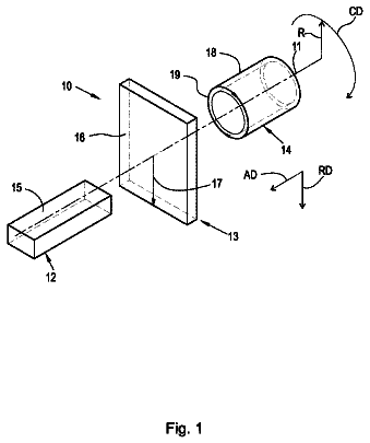
FIG. 1 is a perspective view of a cylindrical coordinate system demonstrating spatial terminology used in the present application;
FIG. 2 is a partial cross-sectional view of a wedge clutch with axially displaceable hubs in a disconnect mode;
FIG. 3 is a partial cross-sectional view of the wedge clutch shown in FIG. 2 in a connect mode;
FIG. 4 is a perspective view of the wedge pin shown in FIG. 2 ;
FIG. 5 is an end view of the wedge pin shown in FIG. 2 ;
FIG. 6 is the partial cross-sectional view of FIG. 3 with a wedge pin and actuation plate removed;
FIG. 7 is a front perspective view of the right-hand hub shown in FIG. 2 ;
FIG. 8 is a back perspective view of the left-hand hub shown in FIG. 2 ;
FIG. 9 is a front view of the right-hand hub shown in FIG. 2 ;
FIG. 10 is a back view of the left-hand hub shown in FIG. 2 ;
FIG. 11 is a front perspective view of the left-hand wedge plate shown in FIG. 2 ;
FIG. 12 is a back perspective view of the right-hand wedge plate shown in FIG. 2 ;
FIG. 13 is a back perspective view of the hubs shown in FIGS. 9 and 10 including an actuation plate and multiple wedge pins;
FIG. 14 is a back view of the actuation plate shown in FIG. 13 ; and,
FIG. 15 is a partial cross-sectional view of a prior art wedge clutch.
Detailed description
At the outset, it should be appreciated that like drawing numbers on different drawing views identify identical, or functionally similar, structural elements of the disclosure. It is to be understood that the disclosure as claimed is not limited to the disclosed aspects.
Furthermore, it is understood that this disclosure is not limited to the particular methodology, materials and modifications described and as such may, of course, vary. It is also understood that the terminology used herein is for the purpose of describing particular aspects only, and is not intended to limit the scope of the present disclosure.
Unless defined otherwise, all technical and scientific terms used herein have the same meaning as commonly understood to one of ordinary skill in the art to which this disclosure belongs. It should be understood that any methods, devices or materials similar or equivalent to those described herein can be used in the practice or testing of the disclosure.
Unless defined otherwise, all technical and scientific terms used herein have the same meaning as commonly understood to one of ordinary skill in the art to which this present disclosure belongs. It should be appreciated that the term “substantially” is synonymous with terms such as “nearly”, “very nearly”, “about”, “approximately”, “around”, “bordering on”, “close to”, “essentially”, “in the neighborhood of”, “in the vicinity of”, etc., and such terms may be used interchangeably as appearing in the specification and claims. It should be appreciated that the term “proximate” is synonymous with terms such as “nearby”, “close”, “adjacent”, “neighboring”, “immediate”, “adjoining”, etc., and such terms may be used interchangeably as appearing in the specification and claims.
FIG. 1 is a perspective view of cylindrical coordinate system 10 demonstrating spatial terminology used in the present application. The present application is at least partially described within the context of a cylindrical coordinate system. System 10 includes longitudinal axis 11 , used as the reference for the directional and spatial terms that follow. Axial direction AD is parallel to axis 11 . Radial direction RD is orthogonal to axis 11 . Circumferential direction CD is defined by an endpoint of radius R (orthogonal to axis 11 ) rotated about axis 11 .
To clarify the spatial terminology, objects 12 , 13 , and 14 are used. An axial surface, such as surface 15 of object 12 , is formed by a plane co-planar with axis 11 . Axis 11 passes through planar surface 15 ; however any planar surface co-planar with axis 11 is an axial surface. A radial surface, such as surface 16 of object 13 , is formed by a plane orthogonal to axis 11 and co-planar with a radius, for example, radius 17 . Radius 17 passes through planar surface 16 ; however any planar surface co-planar with radius 17 is a radial surface. Surface 18 of object 14 forms a circumferential, or cylindrical, surface. For example, circumference 19 is passes through surface 18 . As a further example, axial movement is parallel to axis 11 , radial movement is orthogonal to axis 11 , and circumferential movement is parallel to circumference 19 . Rotational movement is with respect to axis 11 . The adverbs “axially,” “radially,” and “circumferentially” refer to orientations parallel to axis 11 , radius 17 , and circumference 19 , respectively. For example, an axially disposed surface or edge extends in direction AD, a radially disposed surface or edge extends in direction R, and a circumferentially disposed surface or edge extends in direction CD.
FIG. 2 is a partial cross-sectional view of wedge clutch 100 with axially displaceable hubs in a disconnect mode.
FIG. 3 is a partial cross-sectional view of wedge clutch 100 shown in FIG. 2 in a connect mode.
FIG. 4 is a perspective view of the wedge pin shown in FIG. 2 .
FIG. 5 is an end view of the wedge pin shown in FIG. 2 . The following should be viewed in light of FIGS. 2 through 5 . Unless stated otherwise, the reference axis for the terminology shown in FIG. 1 is axis of rotation AR for wedge clutch 100 . Wedge clutch 100 includes: hub 102 ; hub 104 ; outer ring 106 located radially outward of hubs 102 and 104 ; wedge plate 108 radially disposed between hub 102 and outer ring 106 ; wedge plate 110 radially disposed between hub 104 and outer ring 106 ; and wedge pin 112 . Pin 112 includes shaft 114 and actuation ramp 116 non-rotatably connected to shaft 114 . By “non-rotatably connected” elements, we mean that: the elements are connected so that whenever one of the elements rotate, all the elements rotate; and relative rotation between the elements is not possible. Radial and/or axial movement of non-rotatably connected elements with respect to each other is possible, but not required.
In an example embodiment, to transition to a connect mode, for example from a disconnect mode described below, in which hubs 102 and 104 are non-rotatably connected to outer ring 106 : wedge pin 112 is arranged to rotate in rotational direction RD 1 about axis of rotation ARW for pin 112 ; and ramp 116 is arranged to slide along hubs 102 and 104 to displace hubs 102 and 104 away from each other. For example, ramp 116 exerts forces F 1 and F 2 on hubs 102 and 104 , respectively, in directions AD 2 and AD 1 , respectively, parallel to axis AR. In an embodiment, axis ARW is parallel to axis of rotation AR for clutch 100 . Rotation of pin 112 in direction RD 1 is based upon the spiral configuration (discussed below) of pin 112 . It should be understood that the spiral configuration can be reversed such that pin 112 rotates in direction RD 2 , opposite direction RD 1 , to transition to the connect mode.
To transition to a disconnect mode, for example from the connect mode, in which the hubs 102 and 104 are rotatable with respect to outer ring 106 , wedge pin 112 is arranged to: rotate in rotational direction RD 2 , opposite rotational direction RD 1 to reduce axial distance 117 between hubs 102 and 104 . The rotation of ramp 116 in direction RD 2 also relieves forces F 1 and F 2 displacing hubs away from each other. As further described below, relieving forces F 1 and F 2 enables hubs 102 and 104 to move toward each other as shown in FIG. 2 . Rotation of pin 112 in direction RD 2 is based upon the spiral configuration (discussed below) of pin 112 . It should be understood that the spiral configuration can be reversed such that pin 112 rotates in direction RD 1 to transition to the disconnect mode.
Actuation ramp 116 includes: using axis of rotation ARW as a reference axis for the terminology discussed for FIG. 1 , radially outer surface 118 ; surface 120 connecting radially outer surface 118 and shaft 114 ; and surface 122 connecting radially outer surface 118 and shaft 114 . To transition between the connect and disconnect modes, surfaces 120 and 122 are arranged to slide along hubs 102 and 104 . For the connect mode, surfaces 120 and 122 are in contact with hubs 102 and 104 to exert forces F 1 and F 2 . In an example embodiment, surfaces 120 and 122 taper axially toward each other from circumferential end 124 of ramp 116 to circumferential end 126 of actuation ramp 116 , that is, surfaces 120 and 122 taper radially outward toward each other. Stated otherwise, axial extent 128 , parallel to axis ARW, of surface 118 decreases going from end 124 to end 126 . In an example embodiment, radial distance 129 from axis ARW to surface 118 is constant. It should be understood that if pin 112 rotates in direction RD 2 to transition to the connect mode, the positions of ends 124 and 126 would be circumferentially reversed.
FIG. 6 is the partial cross-sectional view of FIG. 3 with wedge pin 112 and an actuation plate removed.
FIG. 7 is a front perspective view of hub 104 shown in FIG. 2 .
FIG. 8 is a back perspective view of hub 102 shown in FIG. 2 .
FIG. 9 is a front view of the hub 104 shown in FIG. 2 .
FIG. 10 is a back view of hub 102 shown in FIG. 2 . The following should be viewed in light of FIGS. 2 through 10 . Hub 102 includes at least one surface 130 disposed at least partially in radial direction RD orthogonal to axis of rotation AR, and hub 104 includes at least one surface 132 disposed at least partially in radial direction RD. For the connect and disconnect modes, surfaces 120 and 122 are arranged to slide along surfaces 130 and 132 . In an example embodiment: surface 130 includes surfaces 130 A and 130 B disposed at least partially in radial direction RD; and surface 132 includes surfaces 132 A and 132 B disposed at least partially in radial direction RD. Surfaces 130 B and 132 B, respectively, are radially inward surfaces 130 A and 132 A, respectively. To transition between the disconnect mode and the connect mode, surfaces 120 and 122 are arranged to slide along the surfaces 130 A, 130 B, 132 A and 132 B. In an example embodiment, hub 102 includes three sets of surfaces 130 A and 130 B and hub 104 includes three sets of surfaces 132 A and 132 B.
In the connect mode, surfaces 120 and 122 are in contact with: one or both of surfaces 130 A and 130 B; and one or both of surfaces 132 A and 132 B. In an example embodiment, in the disconnect mode, surfaces 120 and 122 are in contact with: one or both of surfaces 130 A and 130 B; and one or both of surfaces 132 A and 132 B. In an example embodiment, surfaces 133 A and 133 B of hubs 102 and 104 , respectively, are in contact.
In the connect mode: surfaces 130 A and 132 A are separated by distance 134 in axial direction AD 1 ; and, surfaces 130 B and 132 B are separated by distance 136 in axial direction AD 1 . Distance 136 is greater than distance 134 .
Hub 102 include cavity 138 facing axial direction AD 1 . Hub 104 include cavity 140 facing axial direction AD 2 . At least a portion of pin 112 is located in cavities 138 and 140 . For example, at least a portion of ramp 116 is located in cavities 138 and 140 . Hub 104 includes radial surface 142 facing direction AD 1 and channel 144 connecting cavity 140 and radial surface 142 . Shaft 114 passes through channel 144 . In an example embodiment, hub 104 includes three channels 144 . Hub 102 includes radial surface 141 facing direction AD 2 and channel 145 connecting cavity 138 and radial surface 141 . A portion of shaft 114 is located in channel 145 . In an example embodiment, hub 102 includes three channels 145 .
In an example embodiment: clutch 100 includes actuation plate 146 including opening 148 and shaft 114 includes spiral portion 150 passing through opening 148 . Actuation plate 146 is displaceable in axial direction AD 2 to rotate shaft 114 in rotational direction RD 1 . Actuation plate 146 is displaceable in axial direction AD 1 to rotate shaft 114 in rotational direction RD 2 . To transition between the disconnect mode and the connect mode, plate 146 is arranged to rotate shaft 114 . In an example embodiment, clutch 100 includes actuator 154 arranged to displace actuation plate 146 in axial directions AD 1 and AD 2 . In an example embodiment, wedge pin 112 is in a same axial position, with respect to outer ring 106 , in both the connect and disconnect modes. For example, line 156 in radial direction RD passes through point P 1 on axis AR, point P 2 on ramp 116 , and point P 3 on ring 106 in both the connect and disconnect modes. Displacement of plate 146 in axial directions AD 1 and AD 2 as noted above assumes pin 112 rotates in direction RD 1 to transition to the connect mode. It should be understood that the if pin 112 rotates in direction RD 2 to transition to the connect mode, plate 146 displaces in directions AD 1 and AD 2 to transition to the connect and disconnect modes, respectively. In an example embodiment (not shown), pin 112 extends through channel 145 in hub 102 so that ramp 116 is between hubs 102 and 104 , hub 102 is between plate 146 and hub 104 , pin 112 extends through plate 146 , and a portion of pin 112 is located in channel 144 .
FIG. 11 is a front perspective view of wedge plate 108 shown in FIG. 2 .
FIG. 12 is a back perspective view of wedge plate 110 shown in FIG. 2 . The following should be viewed in light of FIGS. 2 through 12 . Hub 102 includes radially outer surface 158 sloping radially outward toward hub 104 . Hub 104 includes radially outer surface 160 sloping radially outward toward hub 102 . Wedge plate 108 includes radially inner surface 162 sloping radially outward toward wedge plate 110 . Wedge plate 110 includes radially inner surface 164 sloping radially outward toward wedge plate 108 . For the connect mode, wedge pin 112 is arranged to hubs 102 and 104 in axial directions, AD 2 and AD 1 , respectively, to brings surfaces 158 and 162 into contact and to bring surfaces 160 and 164 into contact.
In an example embodiment: surface 158 includes ramps, for example ramp pairs 166 ; surface 160 includes ramps, for example ramp pairs 168 ; surface 162 includes ramps, for example ramp pairs 170 ; and surface 164 includes ramps, for example ramp pairs 172 . For the connect mode, ramp pairs 170 and 172 are arranged to slide radially outwardly along ramp pairs 166 and 168 , respectively, in circumferential direction CD 1 or circumferential direction CD 2 , opposite circumferential direction CD 1 . As further described below, ramps 166 and 170 are engagable and ramps 168 and 172 are engagable.
Each ramp pair 166 includes ramp 166 A extending radially outward in circumferential direction CD 1 and ramp 166 B extending radially outward in circumferential direction CD 2 . Each ramp pair 168 includes ramp 168 A extending radially outward in circumferential direction CD 1 and ramp 168 B extending radially outward in circumferential direction CD 2 . Each ramp pair 170 includes ramp 170 A extending radially outward in circumferential direction CD 1 and ramp 170 B extending radially outward in circumferential direction CD 2 . Each ramp pair 172 includes ramp 172 A extending radially outward in circumferential direction CD 1 and ramp 172 B extending radially outward in circumferential direction CD 2 . Each ramp 166 A is engagable with a respective ramp 170 A. Each ramp 166 B is engagable with a respective ramp 170 B. Each ramp 168 A is engagable with a respective ramp 172 A. Each ramp 168 B is engagable with a respective ramp 172 B.
FIG. 13 is a back perspective view of hubs 102 and 104 shown in FIGS. 9 and 10 including actuation plate 146 and multiple wedge pins 112 .
FIG. 14 is a back view of actuation plate 146 shown in FIG. 13 . The following should be viewed in light of FIGS. 2 through 14 . In an example embodiment, clutch 100 includes three wedge pins 112 and plate 146 includes three openings 148 . The discussion for FIGS. 2 through 10 is applicable to FIGS. 13 and 14 . In an example embodiment, each opening 148 in plate 146 includes protrusion 173 engaged with, for example in contact with, a respective spiral portion 150 passing through each opening 148 . As plate 146 is displaced in direction AD 2 , protrusions 173 , which are fixed with respect to pins 112 , displace through spiral portions 150 , forcing pins 112 to rotate in direction RD 1 . As plate 146 is displaced in direction AD 1 , protrusions 173 displace through spiral portions 150 , forcing pins 112 to rotate in direction RD 2 .
The following provides further detail regarding the structure and function of wedge clutch 100 . Note that torque can be applied to: hubs 102 and 104 for transmission to ring 106 ; or ring 106 for transmission to hubs 102 and 104 . For example, to initiate the connected mode as shown in FIG. 3 , hubs 102 and 104 are axially displaced away from each other by ramp 116 and torque is applied to hubs 102 and 104 in direction CD 1 . As hubs 102 and 104 axially displace away from each other, wedge plates 108 and 110 slide radially outwardly along surfaces 114 and 116 , respectively. Outer circumferential surfaces 174 and 176 of plates 108 and 110 , respectively, frictionally engage inner circumferential surface 178 of ring 106 . Hubs 102 and 104 and wedge plates 108 and 110 are rotating relative to ring 106 in direction CD 1 . Therefore, the frictional engagement of plates 108 and 110 with ring 106 causes plates 108 and 110 to rotate with respect to hubs 102 and 104 , respectively, causing ramps 170 A and 172 A to slide radially outwardly (slide up or climb) along ramps 166 A and 168 A, respectively, which in turn causes wedge plates 108 and 110 to expand radially outward. The radially outward expansion of wedge plates 108 and 110 causes wedge plates 108 and 110 to non-rotatably connect to ring 106 and to hubs 102 and 104 .
In an example embodiment, surface 178 includes chamfers 180 and wedge plates 108 and 110 includes chamfered radially outer portions 182 and 184 , respectively.
To initiate the disconnect mode shown in FIG. 2 , wedge key 112 is rotated in direction RD 2 and wedges hubs 102 and 104 are axially displaced toward each other. For example, when the compressive force on wedge plates 108 and 110 , associated with the connected mode, is released, wedge plates 108 and 110 slide down surfaces 158 and 160 , respectively, creating gaps 186 and 188 , respectively. Since there is little or no contact between wedge plates 108 and 110 and ring 106 , ring 106 and hubs 102 and 104 are able to rotate independently of each other.
The discussion for torque applied in direction CD 1 is applicable to torque applied in direction CD 2 . For example, to initiate the connected mode as shown in FIG. 3 , hubs 102 and 104 are axially displaced away from each other by ramp 116 and torque is applied to hubs 102 and 104 in direction CD 2 . As hubs 102 and 104 axially displace away from each other, wedge plates 108 and 110 slide radially outwardly along surfaces 114 and 116 , respectively. Outer circumferential surfaces 174 and 176 of plates 108 and 110 , respectively, frictionally engage inner circumferential surface 178 of ring 106 . Hubs 102 and 104 and wedge plates 108 and 110 are rotating relative to ring 106 in direction CD 2 . Therefore, the frictional engagement of plates 108 and 110 with ring 106 causes plates 108 and 110 to rotate with respect to hubs 102 and 104 , respectively, causing ramps 170 B and 172 B to slide radially outwardly (slide up or climb) along ramps 166 B and 168 B, respectively, which in turn causes wedge plates 108 and 110 to expand radially outward. The radially outward expansion of wedge plates 108 and 110 causes wedge plates 108 and 110 to non-rotatably connect to ring 106 and to hubs 102 and 104 . The discussion for the disconnect mode and torque in direction CD 1 is applicable to the disconnect mode for torque in direction CD 2 .
Note that the above discussion regarding application of torque through hubs 102 and 104 is applicable to application of torque through ring 106 .
Advantageously, pins 112 serve at least two purposes: to create an initial movement of hubs 102 and 104 to synchronize the respective speeds of outer ring 106 and plates 108 and 110 ; and to lock hubs 102 and 104 in a geometrical defined position to each other during load transmission (connect mode). Locking hubs 102 and 104 has two benefits. First, the high thrust loads generated at the contact of conic surfaces 158 and 162 and at the contact of conic surfaces 160 and 164 cancel each other. Second, hubs 102 and 104 are forced out, by pins 112 , in opposite directions AD 2 and AD 1 , respectively, due to the geometrically defined positioning of hubs 102 and 104 , such that hub movements associated with the connect mode cancel each other to prevent unintended transition from the connect mode to the disconnect mode. Therefore, there is no unintentional and undesirable opening of clutch 100 during the connect mode.
It will be appreciated that various of the above-disclosed and other features and functions, or alternatives thereof, may be desirably combined into many other different systems or applications. Various presently unforeseen or unanticipated alternatives, modifications, variations, or improvements therein may be subsequently made by those skilled in the art which are also intended to be encompassed by the following claims.
 Lapsed, fee not paid10 drawings