Technical field
The present application relates to leaning vehicles.
Background
Typically, snowmobiles have two front skis connected to a handlebar and a rear endless track connected to an engine to propel the snowmobile. In such typical snowmobiles, the snowmobile is steered by turning the handlebar in the direction in which the driver wants to turn. This is known as steer-in-direction. During a turn, the suspension assembly connected to the ski on the outside of the turn is compressed, causing the snowmobile to roll slightly toward the outside of the turn, which the driver can compensate by leaning toward the inside of the turn.
In other vehicles, such as motorcycles, the vehicle is steered by what is known as countersteering. In a motorcycle for example, the motorcycle turns by leaning in the direction of the turn. To achieve this leaning, the driver momentarily turns the handlebar in the direction opposite to the direction of the turn (i.e. the driver countersteers).
Driving a vehicle that can lean into a turn offers a much different driving experience than driving a vehicle that is steer-in-direction. It would be desirable to at least some drivers to have the driving experience of a leaning vehicle on a vehicle having three ground engaging members such as a snowmobile.
U.S. Pat. No. 7,648,148 B1, issued Jan. 19, 2010, and U.S. Pat. No. 7,530,419 B2, issued May 12, 2009, describe three-wheel vehicles that can lean in a turn. In vehicles of this type, the frame of the vehicle is pivotally connected to a shock tower (also known as a transfer frame) and the front shock absorbers associated with the two front wheels are connected at their upper end to the shock tower. During a turn, the frame pivots into the turn like on a motorcycle, but the shock tower remains essentially vertical. As a result, the front shock absorbers do not get compressed due to the leaning of the frame.
In certain conditions, however, operating the vehicle could be complicated by the relative lean between the shock tower and the frame. When traveling along a slope, traveling on areas of low adherence such as ice, or traversing rough terrain at low speeds, leaning could negatively influence the user's control of the vehicle. Further, any such condition may appear when the vehicle is in motion or already leaning away from vertical. For example, when traveling along a slope, the frame of the vehicle could lean toward the downhill side of the slope and increase the possibility of the vehicle tipping over.
Summary
One object of the present invention is to ameliorate at least some of the inconveniences of the prior art.
In one aspect, a brake assembly is provided to act as an angle limiting device to slow or stop the relative lean of a leaning vehicle. The brake assembly offers generally on-the-fly stability control, as a rider of the vehicle can slow or stop leaning motion while the vehicle is in motion, such that the rider is not required to stop the vehicle to change or lock a relative angle between the shock tower and the frame. Further, the brake assembly also allows the rider to slow or stop the leaning motion while the vehicle is already leaning away from vertical, such that the vehicle does not have to be righted before locking the relative angle between the shock tower and the frame.
In another aspect, there is provided a leaning vehicle having a frame having a front portion and a rear portion, a straddle seat mounted on the frame, a motor supported by the frame, a shock tower pivotally connected to the front portion of the frame, the frame being pivotable relative to the shock tower about a pivot axis between an upright position and a plurality of leaning positions, a front left suspension assembly and a front right suspension assembly operatively connected to the front portion of the frame, a front left ground engaging member operatively connected to the front left suspension assembly, a front right ground engaging member operatively connected to the front right suspension assembly, a steering assembly operatively connected to the front left ground engaging member and to the front right ground engaging member to steer the vehicle, the steering assembly having a steering column supported by the frame and a handlebar connected to the steering column, a rear suspension assembly operatively connected to the rear portion of the frame, a rear ground engaging member operatively connected to the rear suspension assembly. Each of the front left suspension assembly and the front right suspension assembly comprise a leg operatively connected to a corresponding one of the front left ground engaging member and the front right ground engaging member, the leg being rotatable about a steering axis, an upper suspension arm having a first end pivotally connected to the frame and a second end pivotally connected to the leg, a lower suspension arm having a first end pivotally connected to the frame and a second end pivotally connected to the leg, the lower suspension arm being lower than the upper suspension arm and a shock absorber having an upper end connected to the shock tower and a lower end connected to the lower suspension arm and a brake assembly connected to the frame and the shock tower.
In some implementations, the brake assembly comprises at least a section of a brake disc connected to one of the frame and the shock tower and a caliper and brake pad assembly connected to another one of the frame and the shock tower, the caliper and brake pad assembly being adapted to apply a braking force to the at least the section of the brake disc.
In some implementations, the braking force applied to the at least the section of the brake disc is adapted for at least one of stopping the frame from pivoting about the pivot axis and reducing a speed of rotation of the frame about the pivot axis.
In some implementations, the vehicle is a snowmobile and wherein the rear portion of the frame includes a tunnel, the front left ground engaging member is a left ski, the front right ground engaging member is a right ski, the rear ground engaging member is an endless track disposed at least in part under the tunnel, the leg of the front left suspension assembly is a left ski leg and the leg of the front right suspension assembly is a right ski leg.
In some implementations, the caliper and brake pad assembly is actuated via an actuator operable by a driver of the vehicle.
In some implementations, the actuator is a lever connected to the handlebar.
In some implementations, the at least the section of the brake disc is connected to the frame and the caliper and brake pad assembly is connected to the shock tower.
In some implementations, the at least the section of the brake disc is disposed in front of the shock tower.
In some implementations, the vehicle further comprises a left stopper connected to one of the frame and the shock tower, the left stopper being adapted to abut another one of the frame and the shock tower when the frame pivots left relative to the shock tower by a first angle thereby limiting pivoting of the frame relative to the shock tower toward the left and a right stopper connected to one of the frame and the shock tower, the right stopper being adapted to abut another one of the frame and the shock tower when the frame pivots right relative to the shock tower by a second angle thereby limiting pivoting of the frame relative to the shock tower toward the right.
In some implementations, the left stopper is a first left stopper and the right stopper is a first right stopper, the vehicle further comprising a second left stopper connected to one of the frame and the lower suspension arm of the front left suspension assembly, the second left stopper being adapted to abut another one of the frame and the lower suspension arm of the front left suspension assembly when the frame has pivoted left relative to the shock tower by the first angle and the shock absorber of the left suspension assembly is compressed by a first amount thereby limiting leaning of the vehicle relative to vertical toward the left and a second right stopper connected to one of the frame and the lower suspension arm of the front right suspension assembly, the second right stopper being adapted to abut another one of the frame and the lower suspension arm of the front right suspension assembly when the frame has pivoted right relative to the shock tower by the second angle and the shock absorber of the right suspension assembly is compressed by a second amount thereby limiting leaning of the vehicle relative to vertical toward the right.
In some implementations, when one of the left stopper and the right stopper abuts the other one of the frame and the shock tower, the steering column is disposed laterally outward of a triangle formed by connection points of the shock absorbers with the shock tower and the pivot axis.
In some implementations, the vehicle further comprises a rack connected to the shock tower, the rack defining a central aperture and a pin operatively connected to the frame and being selectively movable inside the central aperture, the pin locking the frame in the upright position when the pin is received inside the central aperture.
In some implementations, the rack has a left ratchet surface and a right ratchet surface, the pin is further selectively movable to abut the left and right ratchet surfaces when the frame is pivoted left and right respectively relative to the shock tower, when the pin abuts the left ratchet surface, the left ratchet surface prevents the frame from pivoting further toward the left and permits the frame from pivoting toward the right up to the upright position where the pin is received in the central aperture, when the pin abuts the right ratchet surface, the right ratchet surface prevents the frame from pivoting further toward the right and permits the frame from pivoting toward the left up to the upright position where the pin is received in the central aperture.
In some implementations, when the frame is in a maximum leaning position toward a left and the handlebar is turned to steer the skis toward the left, a rear end of the left ski is received in a left recess defined in a left side of the snowmobile and wherein when the frame is in a maximum leaning position toward a right and the handlebar is turned to steer the skis toward the right, a rear end of the right ski is received in a right recess defined in a right side of the snowmobile.
In some implementations, the vehicle further comprises a left side panel connected to the frame rearward of the shock absorber of the front left suspension assembly and a right side panel connected to the frame rearward of the shock absorber of the front right suspension assembly, wherein the left recess is disposed rearward of the shock absorber of the front left suspension assembly and forward of the left side panel and the right recess is disposed rearward of the shock absorber of the front right suspension assembly and forward of the right side panel.
In some implementations, when the frame is in a maximum leaning position toward a left, a center of gravity of the snowmobile is disposed to a left of a contact point between the left ski and a ground and wherein when the frame is in a maximum leaning position toward a right, the center of gravity of the snowmobile is disposed to a right of a contact point between the right ski and the ground.
In some implementations, the vehicle further comprises fairings connected to the frame, wherein when the frame is in a maximum leaning position toward a left, a lowest part of the fairings when the frame is in the maximum leaning position toward the left is disposed vertically higher than a line passing through a lowest point of the front left ground engaging member and a lowest point of the front right ground engaging member when the frame is in the maximum leaning position toward the left and when the frame is in a maximum leaning position toward a right, a lowest part of the fairings when the frame is in the maximum leaning position toward the right is disposed vertically higher than a line passing through a lowest point of the front left ground engaging member and a lowest point of the front right ground engaging member when the frame is in the maximum leaning position toward the right.
In some implementations, the vehicle further comprises a pitman arm connected to the steering column, the pitman arm being pivotable with the steering column about a pivot axis of the steering column and steering rods connecting the pitman arm to the legs, wherein the steering axes of the legs are parallel to the pivot axis of the steering column when the frame is in the upright position.
In yet another aspect, there is provided a snowmobile comprising a frame having a front portion, a straddle seat mounted on the frame, a motor supported by the frame, a front left suspension assembly and a front right suspension assembly operatively connected to the front portion of the frame, a front left ski operatively connected to the front left suspension assembly, a front right ski operatively connected to the front right suspension assembly, the front left and right suspension assemblies and the front left and right skis being pivotable about a pivot axis of the frame, a handlebar operatively connected to the front right and left skis, a rear track operatively connected to the frame, the rear track being pivotable about the pivot axis of the frame and an angle limiting device operatively connected to the frame and the front suspensions, the angle limiting device being adapted for being selectively actuated while the snowmobile is stopped or in motion, the angle limiting device being further adapted for being selectively actuated independent of an angle of rotation of the frame about the pivot axis, the angle limiting device being adapted for at least one of stopping the frame from pivoting about the pivot axis, and reducing a speed of rotation of the frame about the pivot axis.
In some implementations, the angle limiting device is controlled by a rider of the snowmobile during operation of the snowmobile.
In some implementations, the angle limiting device provides a restrictive force to at least one of the frame and the front suspensions.
In some implementations, the angle limiting device is a brake assembly operatively connected to the frame and the front suspensions.
In some implementations, the brake assembly comprises at least a section of a brake disc connected to one of the frame and the front suspensions and a caliper and brake pad assembly connected to another one of the frame and the front suspensions, the caliper and brake pad assembly being adapted to apply a braking force to the at least the section of the brake disc.
In some implementations, the brake assembly is actuated via an actuator operable by a rider of the snowmobile.
In some implementations, the actuator is a lever connected to the handlebar.
In yet another aspect, there is provided a method of operating a leaning vehicle, the method comprising operating the leaning vehicle in a normal operation mode and activating an angle limiting device, the angle limiting device being adapted for performing at least one of reducing a speed of lean of the leaning vehicle, and locking a lean angle of the leaning vehicle.
In some implementations, the activating the angle limiting device occurs while the vehicle is in forward motion.
In some implementations, the activating the angle limiting device occurs while the leaning vehicle is leaning away from vertical.
For purposes of this application, terms related to spatial orientation such as forwardly, rearwardly, upwardly, downwardly, left, and right, are as they would normally be understood by a driver of the vehicle sitting thereon in a normal riding position. Also, the term “ground engaging member” refers to a component of a vehicle making contact with the ground and on which the vehicle is displaced. Examples of ground engaging members include, but are not limited to, skis, wheels and endless tracks.
Embodiments of the present invention each have at least one of the above-mentioned object and/or aspects, but do not necessarily have all of them. It should be understood that some aspects of the present invention that have resulted from attempting to attain the above-mentioned object may not satisfy this object and/or may satisfy other objects not specifically recited herein.
Additional and/or alternative features, aspects, and advantages of embodiments of the present invention will become apparent from the following description, the accompanying drawings, and the appended claims.
Brief description of the drawings
For a better understanding of the present invention, as well as other aspects and further features thereof, reference is made to the following description which is to be used in conjunction with the accompanying drawings, where:
FIG. 1 is a left side elevation view of a leaning snowmobile;
FIG. 2 is a left side elevation view of a frame, front suspension assemblies, skis and exhaust system of the snowmobile of FIG. 1 ;
FIG. 3 is a perspective view taken from a front left side of a front portion of the snowmobile components of FIG. 2 ;
FIG. 4 is a front elevation view of the snowmobile components of FIG. 2 ;
FIG. 5 is a left side elevation view of a front portion of the snowmobile components of FIG. 2 ;
FIG. 6 is a right side elevation view of a front portion of the snowmobile components of FIG. 2 ;
FIG. 7 is a perspective view taken from a front left side of a front portion of the snowmobile components of FIG. 2 , with a portion of the frame and of the left suspension assembly removed;
FIG. 8 is a cross-sectional view of the snowmobile components of FIG. 2 taken through line 8 - 8 of FIG. 2 ;
FIG. 9 is a perspective view taken from a front left side of a front portion of the snowmobile components of FIG. 2 shown leaning toward a left side;
FIG. 10 is a front elevation view of the snowmobile components of FIG. 2 shown leaning toward a left side;
FIG. 11 is a schematic plan view of an outer portion of a track for the snowmobile of FIG. 1 ;
FIG. 12 is a cross-sectional view of the track of FIG. 11 taken through line 12 - 12 of FIG. 11 ;
FIG. 13 is a perspective view, taken from a front, left side, of an alternative embodiment of a leaning snowmobile;
FIG. 14 is a front a front elevation view of the snowmobile of FIG. 13 ;
FIG. 15 is a top plan view of the snowmobile of FIG. 13 ;
FIG. 16 is a left side elevation view of the front portion of the snowmobile of FIG. 13 ;
FIG. 17 is a left side elevation view of a left ski, a front left suspension assembly and elements of a steering assembly of the snowmobile of FIG. 13 ;
FIG. 18 is a perspective view taken from a rear, left side of front portion of the frame, the front suspension assemblies and the skis of the snowmobile of FIG. 13 ;
FIG. 19 is a front elevation view of the snowmobile components of FIG. 18 shown in an upright position;
FIG. 20 is a front elevation view of the snowmobile components of FIG. 18 shown leaning toward a left side;
FIG. 21 is a front elevation view of the snowmobile components of FIG. 18 shown leaning further toward the left side, with the frame removed for clarity;
FIG. 22 is a front elevation view of the snowmobile of FIG. 13 shown leaning toward the left side, with some fairings removed;
FIG. 23 is a left side elevation view of a front portion of the frame, the steering assembly, a left side fairing, the front suspension assemblies and the left ski of the snowmobile of FIG. 13 shown leaning toward the left side, with the left ski being countersteered toward the left and a front part of the left ski being pivoted downward; and
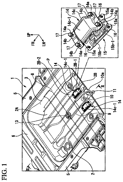
FIG. 24 is a close-up perspective view taken from a front, left side of an alternative embodiment of a shock tower being provided with a brake.
Detailed description
A leaning snowmobile 10 will be described below. It should be understood that aspects of the leaning snowmobile 10 could be applied to other types of leaning vehicles having three or more ground engaging members such as, but not limited to, a three-wheeled vehicle having left and right front wheels and one laterally centered rear wheel.
Referring to FIG. 1 , the snowmobile 10 will be described. The snowmobile 10 has a front end 12 and a rear end 14 , which are defined consistently with the forward travel direction of the snowmobile. The snowmobile 10 has a frame 16 that includes a tunnel 18 , an engine cradle portion 20 ( FIG. 2 ) and a front suspension assembly portion 22 . A motor, which in the present embodiment is an engine 24 that is schematically illustrated in FIG. 1 , is carried by the engine cradle portion 20 of the frame 16 . The engine 24 is a two-stroke, two-cylinder internal combustion engine having two-cylinders, but it is contemplated that the engine 24 could be any type of motor, such as, for example, a four-stroke internal combustion engine or an electric motor. A ski and steering assembly is provided, in which two skis 26 are positioned at the front end 12 of the snowmobile 10 , and are attached to the front suspension assembly portion 22 of the frame 16 through front suspension assemblies 28 that will be described in greater detail below. The skis 26 are operatively connected to a steering assembly including a steering column 30 and a handlebar 32 as will be described in greater detail below.
An endless drive track 34 is positioned at the rear end 14 of the snowmobile 10 and is disposed under the tunnel 18 . The endless drive track 34 is operatively connected to the engine 24 through a reduction drive (not shown) and a belt transmission system 36 which is schematically illustrated by broken lines. In one example, the belt transmission system 36 is a continuously variable transmission (CVT). Drive sprockets (not shown) disposed at a front of the tunnel 18 inside the drive track 34 are driven by the reduction drive and engage drive lugs 37 ( FIG. 12 ) extending from an inner surface of the drive track 34 and/or apertures (not shown) formed along the length of the drive track 34 . Thus, the endless drive track 34 is driven to run about a rear suspension assembly 38 for propulsion of the snowmobile 10 . Terrain lugs 40 A, B (only some of which have been labeled for clarity) are disposed circumferentially about the outer side of the drive track 34 to provide traction to the drive track 34 . Although one embodiment is provided, the specific distribution pattern and dimensions of the terrain lugs will vary depending on the application and desired characteristics of the drive track 34 . The drive track 34 will be described in greater detail below. The rear suspension assembly 38 is connected to the tunnel 18 . The rear suspension assembly 38 includes a pair of slide rails 42 , a front transverse shaft (not shown) connected to the tunnel 18 , a shock absorber 44 connected between the front transverse shaft and the slide rails 42 , and front suspension arms 46 connected between the front transverse shaft and the slide rails 42 . The rear suspension assembly 38 also includes a rear transverse shaft (not shown) connected to the tunnel 18 , a shock absorber 48 connected between the rear transverse shaft and the slide rails 42 , rear suspension arms 50 connected between the rear transverse shaft and the slide rails 42 , and torsion springs 52 (only partially shown) disposed around the rear transverse shaft and having an end supported by the slide rails 42 . A number of wheels 54 are connected to the slide rails 42 and the front and rear transverse shaft and roll along the inner surface of the endless drive track 34 when the snowmobile 10 is in movement. The above-described rear suspension assembly 38 is one possible embodiment of a rear suspension assembly that can be used with the snowmobile 10 . It is contemplated that other embodiments of rear suspension assemblies can be used with the snowmobile 10 .
At the front end 12 of the snowmobile 10 , there are provided fairings 56 that enclose the engine 24 , the reduction drive and the belt transmission system 36 , thereby providing an external shell that not only protects these components, but also make the snowmobile 10 more aesthetically pleasing. The fairings 56 include one or more panels that can be opened to allow access to the engine 24 , the reduction drive, the belt transmission system 36 and other components of the snowmobile 10 disposed inside the fairings 56 . A windshield 58 is connected to the fairings 56 near the front end 12 of the snowmobile 10 , or may alternatively be attached directly to the handlebar 32 . The windshield 58 acts as a windscreen to lessen the force of the air on the rider while the snowmobile 10 is moving.
A seat 60 is connected to and disposed on the tunnel 18 . Two footrests 62 extend laterally from the tunnel 18 on opposite sides of the snowmobile 10 below the seat 60 to accommodate the rider's feet.
The engine 24 receives fuel from a fuel supply system (not shown) including a fuel tank and fuel injectors. Air is supplied to the engine 24 by an air intake system (not shown) including an airbox, a throttle body disposed downstream of the air box, and an air intake manifold fluidly communicating the throttle body with air intake ports (not shown) of the engine 24 disposed on a rear side thereof. Other embodiments of air intake systems are contemplated. For example, one throttle body could be provide per cylinder of the engine 24 , and as such the air intake manifold would be omitted and, if necessary, replaced by one air intake pipe per cylinder for fluidly communicating each throttle body to its corresponding air intake port. Exhaust gases exit the engine 24 via the exhaust ports (not shown) of the engine 24 disposed on a front side thereof. From the exhaust ports, the exhaust gases flow into an exhaust manifold (not shown), then into an exhaust pipe in the form of a tuned pipe 64 ( FIG. 2 ), a muffler 66 ( FIG. 2 ) and finally out to the atmosphere. As can be seen in FIGS. 2 to 10 , the tuned pipe 64 is generally U-shaped and extends in part over the suspension assembly portion 22 . The muffler 66 is disposed on a right side of the engine cradle 20 . Other embodiments of exhaust systems are contemplated.
Turning now to FIGS. 2 to 10 , the suspension assembly portion 22 will be described in more detail. The suspension assembly portion 22 has a metallic extruded frame member 68 fastened to the front of the engine cradle 20 . The extruded frame member 68 is laterally centered. It is contemplated that the extruded frame member 68 could be replaced by a plurality of beams, tubes and/or brackets that are fastened, bonded or welded together. A sheet metal plate 70 is disposed forward of the extruded frame member 68 and is fastened along its top to the extruded frame member 68 . Side plates 72 are fastened to the left and right sides of the extruded frame member 68 and to the front of the engine cradle 20 . The plate 70 has side tabs disposed between the side plates 72 and the extruded frame member 68 and as such the tabs are fastened to the extruded frame members 68 by the fasteners used to fasten the side plates to the extruded frame member 68 . The lower portion of the plate 70 is disposed between a beam 74 and the extruded frame member 68 . The beam 74 is fastened to the extruded frame member 68 by fasteners passing though the lower portion of the plate 70 . A triangular member 76 ( FIG. 7 ) is fastened to the front of the upper part of the plate 70 and is laterally centered. Left and right stopper holders 78 are fastened to the side plates 72 and the side tabs of the plate 70 on either side of the suspension assembly portion 22 . Left and right stoppers 80 are fastened to and extend downwardly from their respective stopper holders 78 . It is contemplated that the stoppers 80 could be integrally formed with the stopper holders 78 or some other portion of the suspension assembly portion 22 . In the illustrated embodiment, the stoppers 80 have a cylindrical metal core with a rubberized outer shell, but other types of stoppers are contemplated. A sheet metal top plate 82 is fastened between the upper forward portions of the side plates 72 . A sheet metal front plate 84 is fastened along its upper edge to the front of the top plate 82 and along its lower edge to the front of the beam 74 . As can be seen, the front plate 84 is spaced from the plate 70 . The front plate 84 , the plate 70 , the beam 74 and the top plate 82 define a cavity therebetween. A bracket 86 is fastened to the lower portion of the front plate 84 and has a tab that is longitudinally spaced from the front plate 84 . It is contemplated that the components of the suspension assembly portion 22 could be made of materials other than metal. For example, it is contemplated that at least some the components of the suspension assembly portion 22 could be made of plastic or composite material. It is also contemplated that at least some of the components of the suspension assembly portion 22 could be bonded, welded or integrally formed with each other instead of being fastened. It is also contemplated that one or more of the plates 70 , 82 , 84 could be replaced by one or more beams, tubes and/or brackets that are fastened, bonded or welded together.
A shock tower 88 is disposed between the plates 70 and 84 . As can be seen in FIGS. 5 and 6 , a portion of the tuned pipe 64 extends forwardly of the shock tower 88 . The shock tower 88 is fixedly mounted onto a shaft 90 ( FIG. 7 ). The ends of the shaft 90 are disposed inside bearings (not shown). The front bearing is received in an aperture (not shown) in the plate 84 and the rear bearing is received in an aperture (not shown) in the plate 70 . As a result, and as will be described in greater detail below, the shaft 90 and the shock tower 88 can pivot about a pivot axis 92 relative to the frame 16 of the snowmobile 10 . The pivot axis 92 is laterally aligned with the longitudinal centerline of the snowmobile 10 when the frame 16 is in an upright position (i.e. the position of the frame 16 shown in FIGS. 2 to 8 ). The shock tower 88 is generally triangular in shape, but other shapes are contemplated. For example, the shock tower 88 could be generally T-shaped with a horizontal bar of the T being at a top of the shock tower 88 . As best seen in FIG. 7 , left and right stoppers 94 are fastened to the top of the shock tower 88 . The stoppers 94 are positioned along the top of the shock tower 88 such that when the frame 16 leans by a predetermined angle relative to the shock tower 88 , the corresponding stopper 94 (i.e. the left stopper 94 when the frame 16 leans left and the right stopper 94 when the frame 16 leans right) makes contact with a corresponding one of the contact surfaces 96 ( FIG. 7 ) defined by the triangular member 76 , as will be described in greater detail below. In the illustrated embodiment, the stoppers 94 have a cylindrical metal core with a rubberized outer shell, but other types of stoppers are contemplated. It is contemplated that the stoppers 94 could be integrally formed with the shock tower 88 . It is also contemplated that the stoppers 94 could be connected to the triangular member 76 , or some other portion of the suspension assembly portion 22 , and that the contact surfaces 96 could be defined on the shock tower 88 . As can be seen in FIG. 7 , when the frame 16 is in the upright position as shown, the stoppers 94 are vertically higher than the stoppers 80 .
A rack 98 is disposed between the plates 70 and 84 and is fastened to the front of the shock tower 88 as shown in FIG. 8 . As such, the rack 98 is fixed relative to the shock tower 88 . As can also be seen in FIG. 8 , the rack 98 has a central aperture 100 located at a lateral center of the rack 98 at a top thereof. The rack 98 also has left and right forwardly facing ratchet surfaces 102 on either sides of the central aperture 100 . The central aperture 100 and the ratchet surfaces 102 generally define an arc having the pivot axis 92 as a center of curvature.
A locking mechanism 104 is mounted onto the front of the plate 84 . The locking mechanism 104 includes an electric motor 106 , a cylinder 108 and a pin 110 ( FIG. 8 ). The pin 110 is slidably received in the cylinder 108 and passes through an aperture (not shown) in the plate 84 in alignment with the central aperture 100 of the rack 98 when the frame 16 is in the upright position. The electric motor 106 selectively slides the pin 110 rearward such that the pin 110 can be received in the central aperture 100 of the rack 98 when the frame 16 is in the upright position. When the pin 110 is received in the central aperture 100 of the rack 98 , the frame 16 is locked in the upright position and cannot pivot relative to the shock tower 88 . When the frame 16 is pivoted from the upright position relative to the shock tower 88 and the electric motor 106 slides the pin 110 rearwardly such that the pin 110 abuts one of the ratchet surfaces 102 , the interaction between the pin 110 and the ratchet surface 102 it abuts prevents the frame 16 from pivoting further away from the upright position, but permits the frame 16 to pivot back to the upright position such that the pin 110 can be received in the central aperture 100 , thereby locking the frame 16 in the upright position. For example, when the frame 16 is pivoted to the left relative to the shock tower 88 as shown in FIGS. 9 and 10 and the electric motor 106 slides the pin 110 rearward to abut the left ratchet surface 102 , the frame 16 is prevented from pivoting further towards the left relative to the shock tower 88 , but can be pivoted toward the right relative to the shock tower 88 up to the upright position. When the electric motor 106 slides the pin 110 forwardly such that the pin 110 is not received in the central aperture 100 and does not abut a ratchet surface 102 of the rack 98 , the frame 16 is free to lean relative to the shock tower 88 until one of the stoppers 94 makes contact with its corresponding contact surface 96 as will be discussed in greater detail below. It is contemplated that the electric motor 106 could be replaced by another type of actuator, such as, but not limited to, a hydraulic actuator or a solenoid. It is also contemplated that the rack 98 could be connected to the rear side of the shock tower 88 , with the ratchet surfaces 102 facing rearwardly and the locking mechanism 104 mounted to a rear surface of the plate 70 .
It is contemplated that the electric motor 106 , and therefore the position of the pin 110 , can be controlled by a switch, buttons or any other input means to be actuated by the driver of the snowmobile 10 . As a result, the driver of the snowmobile 10 can decide to operate the snowmobile 10 as a leaning vehicle by unlocking the frame 16 from the shock tower 88 or to operate the snowmobile 10 as a more typical steer-in-direction snowmobile by locking the frame 16 relative to the shock tower 88 . It is also contemplated that the electric motor 106 could be controlled to automatically move the pin rearward when the snowmobile 10 is operated below a predetermined speed or stopped.
The right front suspension assembly 28 will now be described in more detail. The left front suspension assembly 28 is a mirror image of the right front suspension assembly 28 and will therefore not be described in detail herein. Elements of the left front suspension assembly 28 corresponding to elements of the right front suspension assembly 28 have been labeled with the same reference numerals in the figures.
The right front suspension assembly 28 has upper and lower suspension arms 150 , 152 , a shock absorber 154 and a ski leg 156 .
The upper suspension arm 150 is made of two arms connected at their distal ends to form a generally V-shape. The proximal end of the rear arm of the upper suspension arm 150 is pivotally connected about an upper suspension arm pivot axis 158 in a recess formed in the extruded frame member 68 . The proximal end of the front arm of the upper suspension arm 150 is pivotally connected about the upper suspension arm pivot axis 158 to the front of plate 84 above the bracket 86 . The upper suspension arm pivot axis 158 is parallel to the pivot axis 92 and, as best seen in FIG. 4 , is slightly laterally offset from the pivot axis 92 when the frame 16 is in the upright position. A ball joint 160 is connected to the distal ends of the two arms of the upper suspension arms 150 . A fastener connects the ball joint 160 to an upper portion of the ski leg 156 such that the upper suspension arm 150 is pivotally connected to the ski leg 156 . More specifically, the ball joint 160 is connected to a rear wall of the ski leg 156 .
The lower suspension arm 152 is made of two arms and a cross-member 162 connected between these two arms. The two arms are connected at their distal ends by a connector 163 to form a generally V-shape. The proximal end of the rear arm of the lower suspension arm 152 is pivotally connected about a lower suspension arm pivot axis 164 in a recess formed in the extruded frame member 68 . The proximal end of the front arm of the lower suspension arm 152 is pivotally connected about the lower suspension arm pivot axis 164 between the front of plate 84 and the tab of the bracket 86 . The lower suspension arm pivot axis 164 is parallel to the pivot axis 92 and, as best seen in FIG. 4 , is slightly laterally offset from the pivot axis 92 when the frame 16 is in the upright position. The cross-member 162 and its corresponding stopper 80 are arranged such that the cross-member provides a contact surface for the stopper 80 to abut under certain conditions as will be described in greater detail below. It is contemplated that the stopper 80 could be attached on the cross-member 162 and that a contact surface could be provided on the frame 16 at the position where the stopper 80 is shown in the figures. A ball joint 166 ( FIG. 17 ) is connected to the connector 163 of the lower suspension arms 152 via a connector 168 ( FIG. 4 ). A fastener connects the ball joint 166 to a portion of the ski leg 156 that is vertically below and forward of the ball joint 160 such that the lower suspension arm 152 is pivotally connected to the ski leg 156 . More specifically, the ball joint 166 is connected to a front wall of the ski leg 156 . The connectors 163 and 168 each have a plurality of apertures used to fasten the two together. These apertures allow the longitudinal position of the connector 168 to be changed, which in turn changes the longitudinal position of the ball joint 166 . Changing the position of the ball joint 166 changes the caster angle of the ski leg 156 . The caster angle is the angle between the vertical and a line 170 ( FIG. 3 ) passing through the center of both ball joints 160 , 166 . It is contemplated that the longitudinal position of the lower ball joint 166 could be modified in other ways. For example, the aperture in one or both of the connectors 163 , 168 could be replaced with slots. It is also contemplated that the longitudinal position of the upper ball joint 160 could be adjustable instead of or in addition to the adjustability of the lower ball joint 166 .
The description continues in the full USPTO document.
 Lapsed, fee not paid32 drawings