Background of the invention
1. Field of the invention
The present invention relates to an image forming apparatus.
2. Description of the related art
JP2013-107275A discloses an ink jet printer as an image recording apparatus. Recording heads are disposed in the ink jet printer so as to face the peripheral surface of a platen drum. When a recording medium is transported to a gap between the peripheral surface of the platen drum and the recording head, ink is discharged from the recording head and an image is recorded on the recording medium.
In the ink jet printer, a cooling fan is provided so as to face a portion of the peripheral surface of the platen drum to which a recording medium is GX not transported, and the cooling fan is adapted to cool the platen drum. Accordingly, since the temperature distribution of a recording medium to be transported to the platen drum is suppressed, the formation of wrinkles of the recording medium is suppressed. As a result, a high-quality image can be formed.
Summary of the invention
Incidentally, ink is adjusted to a constant temperature in the ink jet printer. When the temperature of the image forming drum is higher than the temperature of ink by about several ° C., dew condensation occurs on the recording head. For this reason, the discharge of ink from the recording head becomes unstable. The image forming drum can also be cooled by the cooling fan. However, the structure of the cooling fan including a blade, a motor, and the like is complicated and the size of the cooling fan is large. For this reason, there was room for improvement on the ink jet printer.
The invention has been made in consideration of the above-mentioned fact, and an object of the invention is to obtain an image forming apparatus that can stably discharge liquid from a liquid discharge head and can be reduced in size by a simple structure.
In order to solve the above-mentioned problems, an image forming apparatus according to a first aspect of the invention comprises: a recording medium transport unit that is adapted to be capable of transporting a recording medium, which is capable of being held on an outer peripheral portion thereof, from one side of a rotation axis thereof to the other side of the rotation axis by rotating; a liquid discharge head that faces the outer peripheral portion of the recording medium transport unit in a transport range in which the recording medium transport unit is capable of transporting the recording medium and is capable of forming an image on the recording medium by discharging liquid to the recording medium, which is capable of being transported by the recording medium transport unit; and a gas compressor that faces a range positioned outside the transport range deviating from the transport range in a circumferential direction, of the outer peripheral portion of the recording medium transport unit, generates secondary compressed gas, of which the temperature is lower than the temperature of primary compressed gas supplied from the outside of the apparatus, from the primary compressed gas, and blows the secondary compressed gas to the range positioned outside the transport range.
In the image forming apparatus according to the first aspect, the recording medium transport unit can hold the recording medium on the outer peripheral portion thereof, and the recording medium can be transported from one side of a rotation axis thereof to the other side of the rotation axis when the recording medium transport unit rotates. The liquid discharge head is provided so as to face the outer peripheral portion of the recording medium transport unit in the transport range in which the recording medium transport unit is capable of transporting the recording medium. The liquid discharge head is capable of forming an image on the recording medium by discharging liquid to the recording medium that is capable of being transported by the recording medium transport unit. The secondary compressed gas is blown to the range, which is positioned outside the transport range and deviates from the transport range in a circumferential direction, of the outer peripheral portion of the recording medium transport unit from the gas compressor.
Here, since the secondary compressed gas of which the temperature is lower than the temperature of the primary compressed gas is blown to the range, which is positioned outside the transport range, of the recording medium transport unit from the gas compressor, the recording medium transport unit can be cooled. For this reason, the occurrence of dew condensation on the liquid discharge head can be effectively suppressed. Since the primary compressed gas is supplied to the gas compressor from the outside of the apparatus, only the gas compressor is provided in the apparatus and a device for generating the primary compressed gas is not provided in the apparatus. In addition, since the gas compressor generates the secondary compressed gas, of which the temperature is low, from the primary compressed gas, the structure of the gas compressor is simplified and the size of the gas compressor can be reduced.
According to a second aspect of the invention, in the image forming apparatus according to the first aspect, the gas compressor further includes an outlet that blows the secondary compressed gas along a direction of the rotation axis, and the image forming apparatus includes a guide part that guides the secondary compressed gas, which is blown from the outlet, to the range positioned outside the transport range and diffuses the secondary compressed gas in at least the direction of the rotation axis.
According to the image forming apparatus of the second aspect, the secondary compressed gas is blown along the direction of the rotation axis of the recording medium transport unit from the outlet of the gas compressor. The secondary compressed gas is guided to the range, which is positioned outside the transport range, of the recording medium transport unit from the direction of the rotation axis by the guide part, and is diffused at least in the direction of the rotation axis. For this reason, since the length of the flow passage of the secondary compressed gas to the range, which is positioned outside the transport range, from the outlet is increased, the secondary compressed gas to be blown to the recording medium transport unit can be widely diffused along the direction of the rotation axis. Accordingly, since the peripheral surface of the recording medium transport unit can be cooled in a wide range along the direction of the rotation axis, variation in cooling of the recording medium transport unit can be reduced. In addition, since the length of the flow passage of the secondary compressed gas is made along the direction of the rotation axis of the recording medium transport unit, the size of a space, which is required to ensure the length of the flow passage, is reduced. For this reason, the size of the image forming apparatus can be reduced.
According to a third aspect of the invention, in the image forming apparatus according to the second aspect, the guide part includes a guide plate that guides the flow of the secondary compressed gas, and an interior angle between a surface of the guide plate and the rotation axis of the recording medium transport unit is in the range of 30° to 50°.
According to the image forming apparatus of the third aspect, since the guide part includes the guide plate that is set at the angle, it is possible to reduce the amount of the secondary compressed gas that wastefully flows from the gas compressor in the axial direction of the recording medium transport unit. For this reason, since the secondary compressed gas can be guided toward the peripheral surface of the recording medium transport unit without waste, the cooling efficiency of the recording medium transport unit can be improved. In addition, since the secondary compressed gas can be guided by the guide plate, the structure of the guide part is simplified.
According to a fourth aspect of the invention, in the image forming apparatus according to the third aspect, guide walls, which guide the secondary compressed gas in a circumferential direction of the recording medium transport unit, stand at both end portions of the guide plate.
According to the image forming apparatus of the fourth aspect, the guide walls stand at both end portions of the guide plate and the secondary compressed gas is also guided in the circumferential direction of the recording medium transport unit by the guide walls. For this reason, since the secondary compressed gas also flows in the circumferential direction of the recording medium transport unit, the cooling efficiency of the recording medium transport unit can be further improved. In addition, it is possible to collect the secondary compressed gas, which is to be diffused in a direction in which the secondary compressed gas deviates from the recording medium transport unit, and to guide the secondary compressed gas to the peripheral surface of the recording medium transport unit by the guide plate and the guide walls of the guide part. For this reason, since the secondary compressed gas is efficiently used, the cooling efficiency of the recording medium transport unit can be further improved. Moreover, for example, in a case in which heat generating sources are present on the upstream side of the recording medium transport unit in the transport direction of the recording medium and on the downstream side of the recording medium transport unit in the transport direction of the recording medium, the secondary compressed gas is also guided in the circumferential direction of the recording medium transport unit by the guide walls. Accordingly, the wall of the secondary compressed gas can be formed between the recording medium transport unit and each heat generating source. For this reason, since heat, which is transferred to the recording medium transport unit from the heat generating sources, is blocked by the secondary compressed gas, a rise in the temperature of the recording medium transport unit can be effectively suppressed.
According to a fifth aspect of the invention, in the image forming apparatus according to any one of the second to fourth aspects, the guide part is provided immediately below the recording medium transport unit.
According to the image forming apparatus of the fifth aspect, since the guide part is provided immediately below the recording medium transport unit, the length of the flow passage to the peripheral surface of the recording medium transport unit from the guide part is shortest. For this reason, since the secondary compressed gas is blown to the peripheral surface of the recording medium transport unit while maintaining a low temperature, the cooling efficiency of the recording medium transport unit can be further improved.
According to a sixth aspect of the invention, in the image forming apparatus according to any one of the second to fourth aspects, the guide part is provided on the downstream side of a position, which is present immediately below the recording medium transport unit, in a transport direction of the recording medium.
According to the image forming apparatus of the sixth aspect, since the guide part is provided on the downstream side of a position, which is present immediately below the recording medium transport unit, in the transport direction, more secondary compressed gas can be guided to the downstream side in the transport direction than the upstream side in the transport direction in the circumferential direction of the recording medium transport unit. For example, drying processing units are provided on the downstream side of the recording medium transport unit in the transport direction in the image forming apparatus, and the drying processing units are heat generating sources that generate a large amount of heat. For this reason, since the wall of the secondary compressed gas can be formed between the recording medium transport unit and the heat generating source and heat, which is transferred to the recording medium transport unit from the heat generating source, is blocked by the secondary compressed gas, a rise in the temperature of the recording medium transport unit can be effectively suppressed.
According to a seventh aspect of the invention, in the image forming apparatus according to the second aspect, the guide part includes a curved surface or a polygonal surface that protrudes toward a peripheral surface of the recording medium transport unit and guides the secondary compressed gas, or a curved surface or a polygonal surface that is recessed toward a side opposite to the peripheral surface of the recording medium transport unit and guides the secondary compressed gas.
According to the image forming apparatus of the seventh aspect, since the guide part includes a curved surface or a polygonal surface that protrudes toward the peripheral surface of the recording medium transport unit, it is possible to further diffuse the secondary compressed gas, which is guided from the gas compressor by the guide part, in the axial direction of the recording medium transport unit. For this reason, the peripheral surface of the recording medium transport unit can be cooled in a wide range along the direction of the rotation axis. Further, since the guide part includes a curved surface or a polygonal surface that is recessed toward the side opposite to the peripheral surface of the recording medium transport unit, it is possible to cool a specific portion of the peripheral surface of the recording medium transport unit with the secondary compressed gas, which is guided from the gas compressor by the guide part, by aiming a target.
According to an eighth aspect of the invention, in the image forming apparatus according to any one of the second to seventh aspects, the guide part is made of a material that has a thermal conductivity lower than the thermal conductivity of the recording medium transport unit.
According to the image forming apparatus of the eighth aspect, since the guide part is made of a material has a low thermal conductivity, the heat loss of the secondary compressed gas can be reduced in the guide part. For this reason, since the secondary compressed gas, which is maintained at a low temperature, is blown to the peripheral surface of the recording medium transport unit from the gas compressor, the cooling efficiency of the recording medium transport unit can be further improved.
According to a ninth aspect of the invention, in the image forming apparatus according to any one of the first to eighth aspects, the recording medium transport unit is capable of holding the recording medium by receiving and winding the recording medium while rotating.
According to the image forming apparatus of the ninth aspect, the recording medium transport unit can hold a recording medium by receiving and winding the recording medium while rotating. Accordingly, the length, which has a long length, of the transport path of the recording medium in the rotation direction of the recording medium transport unit is obtained. For this reason, the size of the apparatus body can be reduced.
According to a tenth aspect of the invention, in the image forming apparatus according to any one of the first to ninth aspects, the gas compressor is connected to a compressed gas generating source that is provided outside the apparatus and supplies the primary compressed gas.
According to the image forming apparatus of the tenth aspect, since the compressed gas generating source, which supplies primary compressed gas, is provided outside the apparatus, only the gas compressor is provided in the apparatus. For this reason, the structure of an apparatus body is simplified and the size of the apparatus body can be reduced.
According to an eleventh aspect of the invention, in the image forming apparatus according to the tenth aspect, the compressed gas generating source is connected to a blower device that is provided outside the apparatus and discharges heat present in the apparatus to the outside, and is adapted to supply the primary compressed gas to the gas compressor in synchronization with an operation of the blower device.
According to the image forming apparatus of the eleventh aspect, since the primary compressed gas is supplied to the gas compressor from the compressed gas generating source in synchronization with the operation of the blower device, the apparatus body does not require control means for the supply of the primary compressed gas. For this reason, the structure of the apparatus body is simplified and the size of the apparatus body can be reduced.
According to a twelfth aspect of the invention, in the image forming apparatus according to any one of the first to eleventh aspects, the gas compressor is adapted to generate the secondary compressed gas from the primary compressed gas by a vortex effect.
According to the image forming apparatus of the twelfth aspect, the gas compressor can generate the secondary compressed gas, of which the temperature is low, from the primary compressed gas by using a vortex effect.
The invention has an excellent effect of obtaining an image forming apparatus that that can stably discharge liquid from a liquid discharge head and can be reduced in size by a simple structure.
Brief description of the drawings
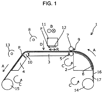
FIG. 1 is a schematic view showing the entire structure of an image forming apparatus according to a first embodiment of the invention.
FIG. 2 is a system configuration diagram of the image forming apparatus, a compressed gas generating source, and an air station including a blower device shown in FIG. 1 .
FIG. 3 is a wiring diagram of control devices of the compressed gas generating source and the air station shown in FIG. 2 .
FIG. 4 is a perspective view of main parts of an image forming drum and gas compressors of the image forming apparatus shown in FIG. 1 seen from the downstream side in a transport direction of a recording medium.
FIG. 5 is an enlarged view of main parts of the image forming drum and a drying processing unit of the image forming apparatus shown in FIG. 1 seen from the side orthogonal to the transport direction.
FIG. 6 is an enlarged perspective view of the gas compressor shown in FIG. 4 .
FIG. 7 is a sectional view of the gas compressor and a guide part shown in FIG. 6 taken along an axial direction.
FIG. 8A is a perspective view of the guide part shown in FIG. 7 , FIG. 8B is a side view of the guide part shown in FIG. 8A seen in a direction of an arrow BL, and FIG. 8C is a front view of the guide part shown in FIG. 8A seen in a direction of an arrow CL.
FIG. 9 is a view showing a positional relationship between the gas compressor, the guide part, and the image forming drum and illustrating a cooling effect and a diffusion effect of compressed gas of the first embodiment.
FIGS. 10A and 10B are views showing relationships between the flow rates of compressed gas of the first embodiment and cooling temperatures.
FIG. 11 is a timing chart showing operations of the image forming drum, the blower device, the compressed gas generating source, and the gas compressor of the image forming apparatus shown in FIG. 2 .
FIGS. 12A to 12D are side views of a guide part of an image forming apparatus according to a second embodiment of the invention corresponding to FIG. 8B . DESCRIPTION OF THE PREFERRED EMBODIMENTS First embodiment
An image forming apparatus according to a first embodiment of the invention will be described with reference to FIGS. 1 to 11 .
(Entire Structure of Image Forming Apparatus)
As shown in FIG. 1 , an image forming apparatus 10 according to this embodiment is adapted to form an image on a sheet-like recording medium (sheet) P with aqueous UV ink (ultraviolet curable ink using an aqueous medium) as photocurable ink by an ink jet method. The image forming apparatus 10 includes, a sheet feed section 12 that feeds a recording medium P, transport means for transporting a recording medium P, a treatment liquid applying section 14 , a treatment liquid drying processing section 16 , an image forming section 18 , an ink fixing processing section 20 that includes a drying processing section 21 and a light irradiation section 22 , control means (not shown) for controlling the entire system, and a sheet discharge section 24 that discharges a recording medium P, as main components.
1. Structure of Sheet Feed Section
The sheet feed section 12 is adapted to feed recording media P, which are loaded on a sheet feed tray 30 , to the treatment liquid applying section 14 one by one. The sheet feed section 12 mainly includes a sheet feed tray 30 , a sucker device 32 , a pair of sheet feed rollers 34 , a feeder board 36 , a front stopper part 38 , and a sheet feed drum 40 .
Recording media P are placed on the sheet feed tray 30 in the form of a bundle in which a plurality of recording media are stacked. The sheet feed tray 30 can be moved up and down by a sheet feed tray lift (not shown). An operation for moving up and down the sheet feed tray is controlled in the sheet feed tray lift while being linked with an increase/decrease in the number of recording media P loaded on the sheet feed tray 30 . In detail, the sheet feed tray is controlled so that the uppermost recording medium P of the bundle is always positioned at a constant height. The recording medium P is not particularly limited, but general-purpose printing sheets, which are used in general offset printing or the like, (sheets using cellulose as a main component, such as so-called high-quality paper, coated paper, and art paper) are used as the recording medium P.
In the sucker device 32 , the recording media P loaded on the sheet feed tray 30 are lifted from the top one by one and are fed to the pair of sheet feed rollers 34 . The sucker device 32 includes a suction foot 32 A that is provided so as to freely move up and down and oscillate. The upper surface of a recording medium P is held by suction by the suction foot 32 A, and the recording medium P is transferred to the pair of sheet feed rollers 34 from the sheet feed tray 30 . In this case, the suction foot 32 A is adapted to hold the upper surface of an end portion of the uppermost recording medium P of the bundle by suction, to lift the recording medium P, and to insert the end of the lifted recording medium P into the pair of sheet feed rollers 34 .
The pair of sheet feed rollers 34 are formed of a pair of upper and lower rollers 34 B and 34 A that come into pressure contact with each other. One of the pair of upper and lower rollers 34 B and 34 A is used as a driving roller (for example, the roller 34 A), and the other thereof is used as a driven roller (for example, the roller 34 B). The driving roller is connected to a motor (not shown), and is driven and rotated by the drive of the motor. The motor is driven while being linked with the feeding of the recording medium P. When the recording medium P is fed from the sucker device 32 , the motor rotates the driving roller at the time of the feeding of the recording medium P. The recording medium P, which is inserted into the pair of sheet feed rollers 34 , is nipped and sent in an installation direction of the feeder board 36 by the pair of sheet feed rollers 34 .
The feeder board 36 is formed so as to correspond to the transport width of the recording medium P and so as to have a width larger than the transport width, and is adapted to guide the recording medium P, which is sent from the pair of sheet feed rollers 34 , to the front stopper part 38 . The downstream portion of the feeder board 36 in a transport direction is inclined downward. For this reason, the recording medium P, which is positioned on a transport path on the feeder board 36 , slides down on the transport path and is guided to the front stopper part 38 .
A plurality of tape feeders 36 A of which a longitudinal direction is parallel to the transport direction are installed in the feeder board 36 at intervals in a width direction intersecting the transport direction. The tape feeders 36 A are adapted to transport a recording medium P. The tape feeders 36 A are formed in the shape of an endless belt, and are adapted to use a motor (not shown) as a driving source and to transport a recording medium P by belts.
Further, retainers 36 B and a roller 36 C are installed on the feeder board 36 . A plurality of retainers 36 B are disposed along the transport path of the recording medium P. The retainers 36 B are used as leaf springs that allow the recording medium P come into pressure contact with the tape feeders 36 A. When the recording medium P, which is transported by the tape feeders 36 A, passes through the retainers 36 B, the irregularity of the recording medium P is corrected. The roller 36 C is provided between the retainer 36 B that is positioned on the upstream side in the transport direction and the retainer 36 B that is positioned on the downstream side in the transport direction, and is adapted to press the recording medium P.
The front stopper part 38 is adapted to correct the posture of the recording medium P during the transport of the recording medium P. The front stopper part 38 is formed of a plate-like member that is orthogonal to the transport direction and comes into contact with the end of the recording medium P in the transport direction. Further, the front stopper part 38 is connected to a motor (not shown), and is driven by the motor so as to be capable of oscillating between the transport path and a non-transport path. The recording medium P of which the posture has been corrected during the transport thereof by the front stopper part 38 is delivered to the sheet feed drum 40 .
The sheet feed drum 40 is adapted to transport the delivered recording medium P to the treatment liquid applying section 14 . The sheet feed drum 40 is a cylindrical rotating body of which an axial direction is parallel to a direction orthogonal to the transport direction, and is adapted to be rotated by a motor (not shown). A gripper 40 A is provided on the outer peripheral surface of the sheet feed drum 40 , and an end of the recording medium P is gripped by the gripper 40 A. The sheet feed drum 40 grips an end of the recording medium P by the gripper 40 A and rotates. Accordingly, the sheet feed drum 40 transports the recording medium P to the treatment liquid applying section 14 while winding the recording medium P around the peripheral surface thereof.
2. Structure of Treatment Liquid Applying Section
The treatment liquid applying section 14 is adapted to apply predetermined treatment liquid to the surface (image forming surface) of the recording medium P. The treatment liquid applying section 14 mainly includes a treatment liquid applying drum 42 that transports a recording medium P, and a treatment liquid applying unit 44 that applies predetermined treatment liquid to the image forming surface of the recording medium P transported by the treatment liquid applying drum 42 . The treatment liquid, which is applied to the surface of the recording medium P, is an aggregating agent having a function to allow a color material (pigment), which is contained in photocurable ink to be discharged (ejected) to the recording medium P in the image forming section 18 provided on the downstream side in the transport direction, to aggregate. Since photocurable ink is discharged after the treatment liquid is applied to the surface of the recording medium P, it is possible to form a high-quality image without causing landing interference and the like even though general-purpose printing sheets are used.
The treatment liquid applying drum 42 is a cylindrical rotating body of which an axial direction is parallel to the axial direction of the sheet feed drum 40 , and is adapted to be rotated by a motor (not shown). A gripper 42 A is provided on the outer peripheral surface of the treatment liquid applying drum 42 , and an end of the recording medium P is gripped by the gripper 42 A. The treatment liquid applying drum 42 grips an end of the recording medium P by the gripper 42 A and rotates. Accordingly, the treatment liquid applying drum 42 transports the recording medium P to the treatment liquid drying processing section 16 while winding the recording medium P around the peripheral surface thereof. When the treatment liquid applying drum 42 makes one rotation, one recording medium P is transported. The rotation of the treatment liquid applying drum 42 and the rotation of the sheet feed drum 40 are controlled so that the time of the reception of the recording medium P and the time of the delivery of the recording medium P correspond to each other. That is, the treatment liquid applying drum 42 and the sheet feed drum 40 are driven so that the circumferential speed of the treatment liquid applying drum 42 and the circumferential speed of the sheet feed drum 40 are equal to each other, and are driven so that the positions of the grippers 40 A and 42 A of the treatment liquid applying drum 42 and the sheet feed drum 40 correspond to each other.
In the treatment liquid applying unit 44 , treatment liquid is applied on the surface of the recording medium P transported by the treatment liquid applying drum 42 . The treatment liquid applying unit 44 mainly includes: an applying roller 44 A that applies treatment liquid to the recording medium P; a treatment liquid tank 44 B in which treatment liquid is stored; and a scooping roller 44 C that scoops treatment liquid, which is stored in the treatment liquid tank 44 B, up and supplies the treatment liquid to the applying roller 44 A.
Treatment liquid has been applied by the applying roller 44 A in this embodiment, but a method of applying treatment liquid is not limited. An applying method using discharge heads having the same structure as ink discharge heads 56 M, 56 K, 56 C, and 56 Y of the image forming section 18 or an applying method using a spray can be used as the method of applying treatment liquid.
3. Structure of Treatment Liquid Drying Processing Section
The treatment liquid drying processing section 16 is adapted to dry the treatment liquid that is applied to the surface of the recording medium P. The treatment liquid drying processing section 16 mainly includes a treatment liquid drying processing drum 46 that transports a recording medium P, a sheet transport guide 48 , and treatment liquid drying processing units 50 that dry treatment liquid by blowing dry air to the image forming surface of the recording medium P transported by the treatment liquid drying processing drum 46 .
The treatment liquid drying processing drum 46 is adapted to receive a recording medium P from the treatment liquid applying drum 42 of the treatment liquid applying section 14 and to transport the recording medium P to the image forming section 18 . The treatment liquid drying processing drum 46 is a cylindrical rotating body of which an axial direction is parallel to the axial direction of the treatment liquid applying drum 42 , and is adapted to be rotated by a motor (not shown). Grippers 46 A are provided on the outer peripheral surface of the treatment liquid drying processing drum 46 , and ends of recording media P are gripped by the grippers 46 A. The treatment liquid drying processing drum 46 grips the ends of the recording media P by the gripper 46 A and rotates. Accordingly, the treatment liquid drying processing drum 46 transports the recording media P to the image forming section 18 . Since the treatment liquid drying processing drum 46 of this embodiment includes the grippers 46 A at two positions on the outer peripheral surface, the treatment liquid drying processing drum 46 is adapted to transport two recording media P during one rotation. The rotation of the treatment liquid drying processing drum 46 and the rotation of the treatment liquid applying drum 42 are controlled so that the time of the reception of the recording medium P and the time of the delivery of the recording medium P correspond to each other. That is, the treatment liquid drying processing drum 46 and the treatment liquid applying drum 42 are driven so that the circumferential speed of the treatment liquid drying processing drum 46 and the circumferential speed of the treatment liquid applying drum 42 are equal to each other, and are driven so that the positions of the grippers 46 A and 42 A of the treatment liquid drying processing drum 46 and the treatment liquid applying drum 42 correspond to each other.
The sheet transport guide 48 is provided along the transport path of the recording medium P so as to face the outer peripheral surface of the treatment liquid drying processing drum 46 . The sheet transport guide 48 is adapted to guide the recording medium P so that the recording medium P does not deviate from the treatment liquid drying processing drum 46 (transport path).
The treatment liquid drying processing units 50 are provided inside the treatment liquid drying processing drum 46 , and are adapted to perform drying processing by blowing dry air to the surface of the recording medium P transported by the treatment liquid drying processing drum 46 . Accordingly, a solvent component contained in the treatment liquid is removed, so that an ink aggregation layer is formed on the surface of the recording medium P. In this embodiment, two treatment liquid drying processing units 50 are provided in the treatment liquid drying processing drum 46 .
4. Structure of Image Forming Section
The image forming section 18 is adapted to form (print, record, or draw) a color or monochrome image on the image forming surface of the recording medium P by discharging liquid droplets of photocurable ink having colors of magenta (M), black (K), cyan (C), and yellow (Y) to the image forming surface of the recording medium P. The image forming section 18 mainly includes an image forming drum 52 serving as a recording medium transport unit, a recording medium pressing roller 54 , ink discharge heads 56 M, 56 K, 56 C, and 56 Y serving as a liquid discharge head, an in-line sensor 58 , and a mist filter 60 . Ink having a magenta color is discharged from the ink discharge head 56 M. Ink having a black color is discharged from the ink discharge head 56 K, ink having a cyan color is discharged from the ink discharge head 56 C, and ink having a yellow color is discharged from the ink discharge head 56 Y. Photocurable ink is used as the ink discharged from each of the ink discharge heads 56 M, 56 K, 56 C, and 56 Y as described above. The photocurable ink is cured by being irradiated with light (here, ultraviolet light) after being discharged.
The image forming drum 52 is adapted to rotate to receive the recording medium P from the treatment liquid drying processing drum 46 of the treatment liquid drying processing section 16 , to be capable of holding the recording medium P on the outer peripheral portion thereof, and to be capable of transporting the recording medium P to the ink fixing processing section 20 . As shown in FIGS. 4 and 5 , the image forming drum 52 is a cylindrical rotating body of which a direction of a rotation axis C is parallel to the axial direction of the treatment liquid drying processing drum 46 , and is adapted to be rotated by a motor (not shown). As shown in FIGS. 1 and 5 , grippers 52 A are provided on the outer peripheral surface of the image forming drum 52 and ends of recording media P are gripped by the grippers 52 A. The image forming drum 52 grips the ends of the recording media P by the gripper 52 A and rotates. Accordingly, the image forming drum 52 transports the recording media P to the ink fixing processing section 20 while winding the recording media P around the peripheral surface thereof.
Here, as shown in FIG. 5 , the peripheral surface (outer peripheral portion) of the image forming drum 52 , which extends in a counterclockwise direction from the treatment liquid drying processing section 16 positioned on one side of the rotation axis C (that is, the upstream side in the transport direction) to the ink fixing processing section 20 positioned on the other side of the rotation axis C (that is, the downstream side in the transport direction), is used as a transport range TR for the recording medium P. In detail, a range between the position, which is denoted by reference numeral P 1 , and the position, which is denoted by reference numeral P 2 , in a counterclockwise direction in FIG. 5 is used as the transport range TR that is a part of the image forming drum in a circumferential direction. Further, a range on the peripheral surface between the position P 2 and the position P 1 in the counterclockwise direction (the other portion of the peripheral surface in the circumferential direction) is used as a non-transport range NT in which the transport of the recording medium P is not performed. That is, the non-transport range NT is a range that deviates from the transport range TR on the outer peripheral portion of the image forming drum 52 in the circumferential direction and is positioned outside the transport range TR. As shown in FIG. 4 , the peripheral surface of the image forming drum 52 as the non-transport range NT is denoted by reference numeral 52 S. That is, two thirds of the upper portion of the image forming drum 52 is used as the transport range TR, and one third of the lower portion thereof is used as the non-transport range NT. Accordingly, while rotating, the image forming drum 52 receives the recording medium P from the treatment liquid drying processing drum 46 at the position P 1 , which is the starting point of the transport range TR, and winds the recording medium P around the peripheral surface thereof by the rotation thereof. Then, while rotating, the image forming drum 52 transports the recording medium P and delivers the recording medium P to the ink fixing processing section 20 at the position P 2 that is the end point of the transport range TR.
Further, a plurality of suction holes (not shown) are formed in a predetermined pattern on the peripheral surface of the image forming drum 52 . Since the recording medium P, which is wound around the peripheral surface of the image forming drum 52 , is sucked through the suction holes, the recording medium P can be transported while being held on the peripheral surface of the image forming drum 52 by suction. Accordingly, the recording medium P can be transported with high smoothness. Suction from the suction holes is performed on the transport path TR. Furthermore, a method of holding the recording medium P is not limited to a suction method using negative pressure, and an attraction method using static electricity may be used.
Moreover, since the grippers 52 A are provided at two positions on the outer peripheral surface of the image forming drum 52 of this embodiment as in the case of the treatment liquid drying processing drum 46 , the image forming drum 52 can transport two recording media P during one rotation. The rotation of the image forming drum 52 and the rotation of the treatment liquid drying processing drum 46 are controlled so that the time of the reception of the recording medium P and the time of the delivery of the recording medium P correspond to each other. That is, the image forming drum 52 and the treatment liquid drying processing drum 46 shown in FIG. 1 are driven so that the circumferential speed of the image forming drum 52 and the circumferential speed of the treatment liquid drying processing drum 46 are equal to each other, and are driven so that the positions of the grippers 52 A and 46 A of the image forming drum 52 and the treatment liquid drying processing drum 46 correspond to each other.
The description continues in the full USPTO document.
 Lapsed, fee not paid8 drawings