 Lapsed, fee not paid19 drawings
Medical Devices · US 9,788,957 B2
Glenoid vault fixation
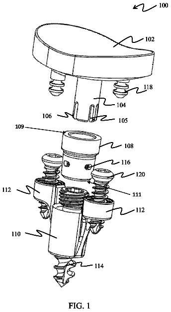
A system is provided which includes an articulating component, a post, a reception member and a bone engaging member.
US 9,788,966 B2 · Assignee: NuVasive, Inc. · Inventors: Steinberg; Amiram
Sheet 1 of 257 from the published document. All sheets in the USPTO PDF
A method of performing a computer-assisted surgical procedure on the spine of a patient comprising the steps of: planning, on a computer, a surgical procedure based on at least one of two- and three-dimensional images of the patient's spine; affixing a robotic assembly over an operative region of the patient; determining, with a computer in communication with the robotic assembly, a desired trajectory of a surgical tool along at least one of an access path and an implant path towards the surgical target site; and placing at least a portion of the surgical tool through the aperture along said desired trajectory along at least one of said access path and said implant path towards the surgical target site.
There exists in the U.S. patent literature a substantial collection of patents relating to apparatus and techniques for treatment of spinal disorders. The following U.S. patents are believed to represent the state of the art: D377,527; D377,096; D377,095; U.S. Pat. Nos. 5,772,661; 5,766,254; 5,755,732; 5,741,261; 5,741,253; 5,735,899; 5,735,852; 5,733,284; 5,730,706; 5,728,127; 5,728,098; 5,728,097; 5,725,582; 5,720,751; 5,720,748; 5,718,877; 5,718,240; 5,716,415; 5,716,357; 5,704,936; 5,702,455; 5,702,449; 5,702,395; 5,702,393; 5,700,292; 5,700,291; 5,700,239; 5,697,929; 5,697,889; 5,690,629; 5,688,274; 5,688,273; 5,688,272; 5,683,464; 5,683,390; 5,676,703; 5,676,701; 5,676,665; 5,675,850; 5,674,296; 5,674,295; 5,672,175; 5,669,909; 5,667,506; 5,665,122; 5,662,686; 5,658,335; 5,653,708; 5,651,789; 5,649,945; 5,647,872; 5,645,598; 5,645,084; 5,643,329; 5,643,263; 5,643,262; 5,643,260; 5,
1 of 257 drawing sheets so far from the published document, cropped to the drawing. Every sheet is in the USPTO PDF.
What the patent claimed, word for word. All of it is now free to use.
The present invention relates to the treatment of spinal disorders generally and more particularly to apparatus and techniques for treatment of spinal disorders. The present invention may also have applicability to other types of surgery employing cannulae.
There exists in the U.S. patent literature a substantial collection of patents relating to apparatus and techniques for treatment of spinal disorders. The following U.S. patents are believed to represent the state of the art: D377,527; D377,096; D377,095; U.S. Pat. Nos. 5,772,661; 5,766,254; 5,755,732; 5,741,261; 5,741,253; 5,735,899; 5,735,852; 5,733,284; 5,730,706; 5,728,127; 5,728,098; 5,728,097; 5,725,582; 5,720,751; 5,720,748; 5,718,877; 5,718,240; 5,716,415; 5,716,357; 5,704,936; 5,702,455; 5,702,449; 5,702,395; 5,702,393; 5,700,292; 5,700,291; 5,700,239; 5,697,929; 5,697,889; 5,690,629; 5,688,274; 5,688,273; 5,688,272; 5,683,464; 5,683,390; 5,676,703; 5,676,701; 5,676,665; 5,675,850; 5,674,296; 5,674,295; 5,672,175; 5,669,909; 5,667,506; 5,665,122; 5,662,686; 5,658,335; 5,653,708; 5,651,789; 5,649,945; 5,647,872; 5,645,598; 5,645,084; 5,643,329; 5,643,263; 5,643,262; 5,643,260; 5,643,259; 5,634,925; 5,634,891; 5,630,816; 5,630,802; 5,624,442; 5,624,441; 5,620,458; 5,618,315; 5,611,800; 5,609,636; 5,609,635; 5,609,592; 5,599,287; 5,599,279; 5,593,409; 5,593,407; 5,591,235; 5,591,165; 5,584,831; 5,571,102; 5,562,736; 5,562,663; 5,562,662; 5,558,674; 5,556,428; 5,549,607; 5,545,166; 5,545,163; 5,540,690; 5,536,268; 5,534,030; 5,534,002; 5,531,745; 5,527,314; 5,522,899; 5,520,690; 5,520,687; 5,505,732; 5,499,983; 5,498,263; 5,498,262; 5,498,233; 5,496,281; 5,489,308; 5,476,464; 5,476,463; 5,476,462; 5,474,555; 5,454,551; 5,458,638; 5,454,812; 5,443,514; 5,439,463; 5,437,669; 5,415,661; 5,415,659; 5,413,576; 5,403,314; 5,390,683; 5,383,884; 5,363,841; 5,314,432; 5,306,309; 5,306,307; 5,306,275; 5,282,862; 5,279,310; 5,267,999; 5,261,913; 5,261,912; 5,261,910; 5,258,019; 5,209,751; 5,112,332; 5,090,758; 5,059,193; 4,854,304; 4,836,196; 4,759,769; 4,714,469; 4,686,970; 4,573,454; 4,445,513; 4,401,112; 4,085,744; 4,047,524; 4,041,939.
The current state of the art relating to lumbar disc surgery is described in Current and Future Approaches to Lumbar Disc Surgery (A Literature Review) by C. H. Alleyne Jr. and G. E. Rodts Jr. Medscape Orthopedics & Sports Medicine which appears on the Internet on http://www.medscape.coni/Medscape/OrthoSportsMed/1997/v01.n11; mos30518/07/98mos3, as well as in the references cited therein. The disclosures of all patent and literature references, mentioned in this Background of the Invention section, are hereby incorporated by reference.
The present invention seeks to provide improved apparatus and techniques for treatment of spinal disorders. The present invention also seeks to provide apparatus and techniques for other types of surgical treatment employing cannulae.
According to a first aspect of the present invention there is provided an implant for use in spinal surgery comprising:
a resilient element having an inflatable cavity, the resilient element being formed of a biologically compatible material and being arranged for placement between end plates of adjacent vertebra.
In an embodiment, the resilient element comprises an inflation valve operatively associated with the inflatable cavity, which permits inflation of the cavity to cause the resilient element to be in an inflated state and subsequent sealing of the cavity to retain the resilient element in the inflated state.
In a further embodiment the resilient element comprises an inflation conduit communicating with the inflation valve and extending outwardly thereof at least to a periphery of the end plates.
In yet a further embodiment the resilient element comprises a plurality of lateral projections for engagement with a disc replacement coil.
In yet a further embodiment there is provided a disc replacement coil lead wound about the resilient element.
According to a second aspect of the present invention there is provided an implant for use in spinal surgery comprising:
a disc replacement coil, the disc replacement coil being formed of a biologically compatible material and being arranged for placement between end plates of adjacent vertebra.
A preferred embodiment also comprises a resilient element having an inflatable cavity, the resilient element being formed of a biologically compatible material and being arranged for placement between end plates of adjacent vertebra interiorly of the disc replacement coil.
In yet a further embodiment a seat element is seated in a recess formed in the resilient element, the seat element defining a generally circular inner recess, which defines a bearing race and retains therein a plurality of balls, thus defining a bearing.
In yet a further embodiment the seat element defines an outer recess which corresponds to the recess formed in the resilient element and also defines an outer flange which rests against a surface of the resilient element.
In yet a further embodiment a circular sprocket is rotatably seated in the outer recess of the seat element in bearing relationship with the balls in the bearing race.
In yet a further embodiment the circular sprocket includes an underlying bearing race defining a circular recess, an inner circular array of outwardly facing teeth, which is engaged by a toothed drive belt and an outer circular array of outwardly facing teeth, each of which is formed with a transverse recess.
In yet a further embodiment the outer circular array of outwardly facing teeth drivingly engages a correspondingly configured upstanding disc replacement coil for winding thereof.
In yet a further embodiment the sprocket also includes an overlying bearing race defining a circular recess which retains therein a plurality of balls, thus defining a bearing.
In yet a further embodiment the resilient element comprises a slightly curved generally planar, oval-shaped cover portion which corresponds in shape to a machined configuration of an adjacent facing plate of a vertebra, for secure seating therein and optimized distribution of pressure and forces thereon and shock absorbing.
In yet a further embodiment an outer surface of the cover portion includes a slightly curved generally planar surface, first and second elongate edge surfaces and a curved edge surface, the edge surfaces being joined together so as to define a continuous peripheral edge surface and being joined with the planar surface in a generally seamless manner to define a smooth outer surface of the resilient element.
In yet a further embodiment the cover portion is formed with a generally circularly ring-shaped bearing race, defining a recess at an inner facing surface.
In yet a further embodiment there is provided a base member which underlies the resilient element and which corresponds in shape to a machined configuration of an adjacent facing plate of a vertebra, for secure seating therein and optimized distribution of pressure and forces thereon and shock absorbing.
In yet a further embodiment there is provided first and second generally oval ring-shaped recesses formed in a surface of the resilient element.
In yet a further embodiment there is provided a rigid peripheral band formed at peripheral surfaces of the resilient element and which is secured in a peripheral recess.
In yet a further embodiment there is provided a seat element having a circular array of bearing roller retaining recesses and corresponding cylindrical bearing rollers which are disposed on an inner surface of an outer recess and having a central recess, located interiorly of the circular array of bearing roller retaining recesses.
In yet a further embodiment there is provided a second sprocket having a motor which provides rotation of outwardly facing teeth.
In yet a further embodiment the outwardly facing teeth are formed with a transverse recess.
In yet a further embodiment there is provided a base member which has formed on an outer facing peripheral surface thereof a bearing race defining an outer facing recess.
In yet a further embodiment the disc replacement coil comprises a sprocket engagement belt having inwardly facing teeth arranged for operative engagement with an outer circular array of outwardly facing teeth of a sprocket.
In yet a further embodiment the belt is assembled over the sprocket and is retained thereon by means of an inner facing peripheral protrusion which engages a transverse recess formed in the outwardly facing teeth.
In yet a further embodiment there is provided an upstanding coil winding portion extending from the engagement belt.
In yet a further embodiment the upstanding coil winding portion is formed with an extra thick portion which, when wound about the resilient element, seats under the engagement belt.
In yet a further embodiment, the upstanding coil winding portion is formed with either or both of a fiber reinforcing layer and a compression wire.
In yet a further embodiment, the upstanding coil winding portion is formed with a varying thickness, whereby the thickness of the upstanding coil when wound at various locations thereat corresponds to the desired configuration of the resulting replacement disc.
In yet a further embodiment, the upstanding coil winding portion is formed with varying mechanical properties, whereby the characteristics of the upstanding coil when wound at various locations thereat correspond to the desired characteristics of the resulting replacement disc.
In yet a further embodiment, the upstanding coil winding portion is wound about the resilient element by rotation of the sprocket, causing the upstanding coil winding portion to be tightly wound about the engagement belt and thus about the resilient element.
In yet a further embodiment, the upstanding coil winding portion is retained in a desired wound arrangement by means of engagement between one or more suitably disposed protrusions and corresponding sockets disposed adjacent an outer end of the coil winding portion.
In yet a further embodiment, the upstanding coil winding portion is formed with a series of apertures or outwardly facing sockets which may be engaged by an auxiliary coiling tool to assist in winding the coil winding portion about the resilient element.
In yet a further embodiment, the upstanding disc replacement coil includes a bearing race defining protrusion or recess retaining bearing balls therein, the protrusion or recess being located on a portion of the coil winding portion adjacent an engagement belt and positioned so that upon winding thereof about the engagement belt, bearing balls engage the bearing race.
In yet a further embodiment, the upstanding disc replacement coil includes a bearing race defining protrusion or recess engaging bearing rollers, the protrusion or recess being located on a portion of the coil winding portion adjacent an engagement belt and positioned so that upon winding thereof about the engagement belt, bearing rollers engage the bearing race.
In yet a further embodiment, the upstanding disc replacement coil includes a non flat cross-section along at least part of its length, wherein the coil winding portion terminates in a tail portion which is readily separable therefrom by a perforation.
In yet a further embodiment, the non flat cross-section defines at least one elongate recess on a first surface of a portion thereof and at least one pair of matching elongate recesses on a second surface of the portion.
In yet a further embodiment, the relative locations of the first and second surfaces are selected such that when the coil winding portion is tightly wound about the resilient element, the recesses on the first and second surfaces face each other and together define an enclosed space suitable for insertion thereinto of a flowable elastomer.
In yet a further embodiment, a non-flat cross-section is located along either or both of the top and bottom edges of the upstanding disc replacement coil.
In yet a further embodiment, either or both of the top and bottom edges are configured to at least partially lockingly engage with one or more of the peripheral recesses formed by suitable machining of end plates of vertebrae.
In yet a further embodiment, the peripheral recesses are formed with an undercut configuration and the cross-sections of at least one of the top and bottom edges are correspondingly configured.
In yet a further embodiment, the disc replacement coil comprises multiple turns of a generally flat coil element.
In yet a further embodiment, the end plates lie generally in parallel planes and wherein the generally flat coil element lies generally in planes parallel to the parallel planes of the end plates.
In yet a further embodiment, the generally flat coil element includes portions having convex rounded cross-sectional surfaces which are seated in peripheral channels of respective ones of the end plates.
In yet a further embodiment, the generally flat coil element includes portions having undercut concave cross-sectional surfaces which face peripheral channels of respective ones of the end plates and a flowable polymer is inserted to fill interstices between adjacent coils at the concave cross-sectional surfaces and at the peripheral channels.
In yet a further embodiment, the generally flat coil element includes portions having undercut convex cross-sectional surfaces which lockingly seat in peripheral channels of respective ones of the end plates.
In yet a further embodiment, the generally flat coil element includes at least one rib and at least one lip, which engage hook-like portions of respective ones of the coils.
In yet a further embodiment, the generally flat coil element includes at least one flat disc replacement coil having formed thereon protrusions seating in respective recesses formed thereon.
In yet a further embodiment, the generally flat coil element includes at least one flat disc replacement coil which is held together by engagement elements.
In yet a further embodiment, the engagement elements lie in peripheral recesses formed in the end plates and are retained therein by means of a flowable polymer.
In yet a further embodiment, the generally flat coil element includes a double coil installed in situ between facing vertebrae.
In yet a further embodiment, the end plates lie generally in parallel planes and wherein the generally flat coil element lies generally perpendicular to the parallel planes of the end plates.
In yet a further embodiment, the resilient element comprises an inflation valve operatively associated with the inflatable cavity, which permits inflation of the cavity to cause the resilient element to be in an inflated state and subsequent sealing of the cavity to retain the resilient element in the inflated state.
In yet a further embodiment, the resilient element comprises an inflation conduit communicating with the inflation valve and extending outwardly thereof at least to a periphery of the end plates.
In yet a further embodiment, the resilient element comprises at least one generally bandlike peripheral protrusion having peripheral edges.
In yet a further embodiment, the peripheral edges are undercut.
In yet a further embodiment, the at least one protrusion comprises two discrete protrusions.
In yet a further embodiment, there is provided an implant portion which extends to the periphery of the end plates and enables injection of body substances earlier removed from a nucleus pulposus to the region between the end plates.
In yet a further embodiment, there is provided one or more disc replacement bands.
In yet a further embodiment, the disc replacement band has an overall configuration generally corresponding to a peripheral edge of the inflatable implant.
In yet a further embodiment, each disc replacement band is formed with an aperture on an outer facing side surface thereof, for engagement by a tool.
In yet a further embodiment, each disc replacement band is formed with retaining sockets at an inner facing side surface thereof.
In yet a further embodiment, each disc replacement band is formed of mechanically suitable, biologically compatible elastomer and includes a fiber reinforcing layer and/or a compression wire.
In yet a further embodiment, each disc replacement band is a solid band having respective top and bottom peripheral protrusions of generally partially circular cross-section and inner and outer side surfaces which are respectively concave and convex.
In yet a further embodiment, each disc replacement band is a solid band having respective top and bottom peripheral protrusions of generally partially circular cross-section and inner and outer side surfaces which respectively bear a peripheral undercut protrusion and a peripheral undercut socket, having undercut top and bottom edges.
In yet a further embodiment, each disc replacement band is a solid band having respective top and bottom peripheral protrusions of generally partially circular cross-section and inner and outer side surfaces, the inner side surface being formed with a peripheral undercut socket.
In yet a further embodiment, each disc replacement band is a solid band having respective top and bottom peripheral protrusions of generally partially circular cross-section and inner and outer side surfaces which respectively bear peripheral sockets, having undercut top and bottom edges.
In yet a further embodiment, each disc replacement band is a hollow band having a void and having respective top and bottom peripheral protrusions of generally partially circular cross-section and inner and outer side surfaces which are respectively concave and convex.
In yet a further embodiment, each disc replacement band includes recesses formed at two facing inner side surface locations which are adapted to receive corresponding protrusions of the inflatable implant.
In yet a further embodiment, the recesses include a generally concave inner side surface and a generally convex outer side surface
In yet a further embodiment, the recesses are defined by a tapering surface, which terminate at an inner surface.
In yet a further embodiment, each disc replacement band is formed with an aperture on an outer facing side surface thereof, for engagement by a tool.
In yet a further embodiment, each disc replacement band is formed with retaining sockets at an inner facing side surface thereof.
In yet a further embodiment, each disc replacement band is a solid band having respective top and bottom peripheral protrusions of generally partially circular cross-section.
In yet a further embodiment, each disc replacement band is formed of a mechanically suitable, biologically compatible elastomer and includes at least one of a fiber reinforcing layer and at least one compression wire.
In yet a further embodiment, each disc replacement band is formed with two injection conduits for injection thereinto of a flowable polymer.
In yet-a further embodiment, each disc replacement band is formed with a generally U-shaped cross-section defining a slightly convex outer side surface and generally flat top and bottom surfaces, defining inwardly facing edges having a cross-sectional curvature which matches the configuration of peripheral edges of the inflatable implant.
In yet a farther embodiment, each disc replacement band is configured at top and bottom surfaces thereof with apertures distributed along the circumference of the band, whereby flowable polymers, injected into spaces between adjacent bands and between the inflatable implant and a band, flows outwardly through the apertures into undercut recesses in the end plates.
In yet a further embodiment, each disc replacement band is configured with outer facing top and bottom corner edge recesses as well as apertures distributed along the circumference of its side surface.
In yet a further embodiment, each disc replacement band comprises generally flat top and bottom surfaces defining inwardly facing edges.
In yet a further embodiment, the disc replacement coil comprises a main coil portion including a plurality of coils having at least three differing cross-sections and a tail portion which is removably connected to the main coil portion.
In yet a further embodiment, the disc replacement coil comprises a head portion having a generally conical configuration and a lead coil portion, the head portion having a maximum cross-sectional dimension which is slightly greater than the maximum cross-sectional dimension of the lead coil portion.
In yet a further embodiment, the disc replacement coil comprises a main coil portion including a plurality of coils at least one of which having a first generally omega-shaped cross-section.
In yet a further embodiment, the first generally omega-shaped cross-section comprises a central region including a convex rounded cross-sectional surface which corresponds to a cross-sectional configuration of a channel formed in an end plate and a concave rounded cross-sectional surface.
In yet a further embodiment, the plurality of coils includes at least one coil having a generally rectangular cross-section and a central rounded protrusion at the center thereof, defining a plurality of convex rounded cross-sectional surfaces at least one of which being configured to seat in the concave rounded surface.
In yet a further embodiment, the plurality of coils includes at least one coil having a second generally omega-shaped cross-section.
In yet a further embodiment, the second generally omega-shaped cross-section is a mirror-image of the first generally omega-shaped cross-section.
In yet a further embodiment, the plurality of coils includes at least one coil having a third generally omega-shaped cross-section, identical to the second generally omega-shaped cross-section.
In yet a further embodiment, the plurality of coils includes at least one coil which includes at an inner facing edge thereof a hook-like portion which is configured to lockingly engage a lip and a rib of an inflatable implant.
In yet a further embodiment, the plurality of coils includes at least one coil which is formed with a transverse recess which permits access to an inflation valve.
In yet a further embodiment, the plurality of coils includes at least one coil having inner facing edges formed to define channels which are configured to lockingly engage corresponding surfaces of a protrusion of an inflatable implant.
In yet a further embodiment, the disc replacement coil comprises a connector coupled to a main coil portion via a perforated junction.
In yet a further embodiment, the connector is configured and adapted to be readily mechanically coupled to an engagement socket of a coiled lead of an inflatable implant.
In yet a further embodiment, the disc replacement coil is formed with undercut recesses on each of respective top and bottom surfaces thereof.
In yet a further embodiment, the recesses extend substantially along the entire length of the coil.
In yet a further embodiment, the disc replacement coil is formed with a generally rectangular cross-section having a first hook-like portion at an inner, bottom facing corner thereof and having a second hook-like portion at an outer, top facing corner thereof.
In yet a further embodiment, the disc replacement coil is formed with a generally rectangular cross-section having a central slanted recess at a top facing surface thereof.
In yet a further embodiment, the disc replacement coil is formed with a generally rectangular cross-section having two differing widths along its length defining a corrugated configuration.
In yet a further embodiment, the disc replacement coil is formed with teeth and corresponding recesses which do not extend over the entire width of the coil, and thus serve to mutually align the individual coils in three dimensions.
In yet a further embodiment, the disc replacement coil is formed with opposing engagement elements of two different types which are designed for secure engagement therebetween.
According to a third aspect of the present invention there is provided an implant for use in spinal surgery comprising:
a disc replacement band assembly, the disc replacement band assembly being formed of a biologically compatible material and being arranged for placement between end plates of adjacent vertebra.
In an embodiment, there is further provided a resilient element having an inflatable cavity, the resilient element being formed of a biologically compatible material and being arranged for placement between end plates of adjacent vertebra interiorly of the disc replacement band assembly.
In yet a further embodiment, the disc replacement band assembly comprises at least one generally flat band element.
In yet a further embodiment, the end plates lie generally in parallel planes and the at least one generally flat band element lies generally perpendicular to the parallel planes of the end plates.
In yet a further embodiment, the resilient element comprises an inflation valve operatively associated with the inflatable cavity, which permits inflation of the cavity to cause the resilient element to be in an inflated state and allows subsequent sealing of the cavity to retain the resilient element in the inflated state.
In yet a further embodiment, the resilient element comprises an inflation conduit communicating with the inflation valve and extending outwardly thereof at least to a periphery of the end plates.
According to a fourth embodiment of the present invention there is provided an implant for use in spinal surgery comprising:
a wound disc replacement element, the wound disc element being formed of a biologically compatible material and being arranged for placement between end plates of adjacent vertebra.
In yet a further embodiment, the wound disc replacement element comprises a wound filament.
In yet a further embodiment, the wound disc replacement element comprises a wound strip.
In yet a farther embodiment, a resilient element has an inflatable cavity, is preferably formed of a biologically compatible material and is preferably arranged for placement between end plates of adjacent vertebra interiorly of a disc replacement coil.
In yet a further embodiment, the resilient element comprises an inflation valve operatively associated with the inflatable cavity, which permits inflation of the cavity to cause the resilient element to be in an inflated state and allows subsequent sealing of the cavity to retain the resilient element in the inflated state.
In yet a further embodiment, the resilient element comprises an inflation conduit communicating with the inflation valve and extending outwardly thereof at least to a periphery of the end plates.
In yet a further embodiment, the resilient element comprises a pair of generally planar surfaces and a peripheral edge surface, which are configured to correspond to the configuration of a corresponding recess formed in at least one end plate for secure seating therein, optimization of distribution of pressure and forces thereon and shock absorbing.
In yet a further embodiment, the resilient element also comprises a multi-coil spiral outwardly extending rib located on the peripheral edge surface.
In yet a further embodiment, the resilient element also comprises a lip formed onto the multi-coil spiral outwardly extending rib for providing enhanced locking engagement of a disc replacement implant with the resilient element.
In yet a further embodiment, the resilient element also comprises a protrusion formed onto the multi-coil spiral outwardly extending rib for providing enhanced locking engagement of a disc replacement implant with the resilient element.
A yet further embodiment comprises a lead coiled about the resilient element along the multi-coil spiral outwardly extending rib.
In yet a further embodiment, the lead is formed with engagement elements at opposite ends thereof, one of such engagement elements being adapted to be attached to a forward end of a flat disc replacement coil, another one of such engagement elements being adapted to be hooked onto by a suitable pulling tool.
In yet a further embodiment, the disc replacement coil comprises a head, a lead coil portion, a main coil portion and a tail portion.
In yet a further embodiment, the main coil portion comprises, at an inner facing edge thereof, a hook-like portion which is configured to lockingly engage the resilient element.
In yet a further embodiment, the main coil portion is formed with at least one undercut recess on at least one surface thereof, the recess extending along the length of the main coil portion.
In yet a further embodiment, the main coil portion is also formed with at least one undercut protrusion on a surface thereof, the protrusion extending along the length of the main coil portion and being configured for locking engagement with the at least one undercut recess.
In yet a further embodiment, the main coil portion is formed with a first hooking portion on a surface thereof, the first hooking portion extending along the length of the main coil portion.
In yet a further embodiment, the main coil portion is also formed with a second hooking portion on a surface thereof, the second hooking portion extending along the length of the main coil portion and being configured for locking engagement with the first hooking portion.
In yet a further embodiment, at least a portion of the disc replacement coil has a generally rectangular cross-section having toothed opposite facing surfaces.
In yet a further embodiment, the toothed opposite facing surfaces do not extend over the entire width of the coil, and thus serve to mutually align overlapping portions of the coil in three dimensions.
In yet a further embodiment, at least a portion of the disc replacement coil is formed with opposite facing hook-type mutually engaging surfaces.
A yet further embodiment, has an overall wedge shaped configuration.
According to a fifth aspect of the present invention there is provided a method of performing spinal surgery on a patient comprising:
securely mounting a patient onto a patient support table;
imaging a spinal region of the patient;
building up a three dimensional image file of the spinal region of the patient;
storing the image file;
utilizing the image file for planning and carrying out computer controlled spinal surgery on the patient.
In an embodiment, there is further provided the step of planning and visualizing a computer controlled surgical approach path, in order to maximize avoidance of vital organs, nerves and blood vessels.
In a further embodiment, the utilizing step employs patient data stored in a computer memory as well as imaging data derived from earlier patient imaging and reference medical data, and the reference medical data includes medical imaging information currently available on computer networks.
In yet a further embodiment, the imaging step comprises determining a desired patient orientation for pre-operative imaging and performing computer simulated imaging based on the desired patient orientation.
In yet a further embodiment, the securely mounting step includes orienting the support table by downloading data indicating a desired patient orientation from a computer.
In yet a further embodiment, patient imaging is supplemented in a region of interest with medical reference data and composite images are provided, characterized in that patient imaging data is clearly distinguished from overlaid reference data.
In yet a further embodiment there are provided the steps of determining a navigation path of a first cannula subassembly in three spatial dimensions and over time; and
determining an anchoring location for the first cannula subassembly.
In yet a further embodiment, there is provided a second cannula subassembly, and there are further provided the steps of:
determining the pathway and timing of the insertion of a third cannula subassembly over first and second cannula subassemblies; and
determining an intended anchoring location for the third cannula subassembly.
In yet a further embodiment, the utilizing step comprises:
determining the timing of removal from the body of the patient of a first cannula subassembly, a second cannula subassembly and an inner portion of a third cannula subassembly; and
determining the timing and technique to be used for suctioning of a disc.
In yet a further embodiment, the utilizing step comprises:
planning restoration of end plates of vertebrae utilizing surgical vehicles and milling tools.
In yet a further embodiment, the restoration includes an initial milling stage defining a recess for a generally “bean shaped” inflatable pillow.
In yet a further embodiment, the restoration also comprises defining at least one channel in the end plate.
In yet a further embodiment, there is provided the step of planning insertion of an inflatable implant in a recess formed in at least one end plate.
In yet a further embodiment, the restoration comprises insertion of a top surface plate following suitable machining of the top surface of an end plate.
In yet a further embodiment, the restoration comprises providing a recess encompassing a buckled portion of an end plate for receiving a bone graft and inserting a bone graft in the recess.
In yet a further embodiment, the restoration comprises providing treatment for scoliosis by providing a seat and a channel for securely receiving a bone graft and inserting a bone graft at the seat and the channel with precise dimensions corresponding to those of the seat and the channel such that a portion of the bone graft protrudes from a top surface of the end plate.
In yet a further embodiment, there is provided the step of planning insertion of an inflatable implant between end plates of adjacent vertebra by employing tools including an inflation tool in association with a surgical vehicle.
In yet a further embodiment, there is provided the step of planning insertion of a disc replacement implant surrounding the inflatable implant.
In yet a further embodiment, the disc replacement implant comprises a flat disc replacement coil.
In yet a further embodiment, the disc replacement implant comprises an upstanding disc replacement coil.
In yet a further embodiment, the utilizing step comprises carrying out a simulated operation on a computer in an off-line manner.
In yet a further embodiment, the step of carrying out a simulated operation employs stored patient image data and is linked to the intended configuration of the implant and its operating environment.
In yet a further embodiment, during the step of carrying out a simulated operation, the surgeon modifies at least one aspect of a planned operation.
A yet further embodiment includes applying computerized analysis to the simulated operation.
A yet further embodiment includes providing computer generated comments and warnings to an operator based on the computerized analysis.
In yet a further embodiment, there is provided the additional step of planning disc suctioning.
In yet a further embodiment, the step of utilizing the image file for planning and carrying out computer controlled spinal surgery on the patient, comprises the steps of:
extracting a cannula entry position from a final real time starting operation plan;
positioning the patient as required; and
inserting the first cannula subassembly into the patient in accordance with the final real time starting operation plan as modified interactively in real time by the surgeon.
In yet a further embodiment, the step of inserting the first cannula subassembly into the patient comprises the steps of:
initiating penetration of the first cannula subassembly into the patient; and
using the final real time starting operation plan as modified interactively in real time by the surgeon, causing a desired sequence of coordinated movements of the first cannula subassembly, the coordinated movements including one or more of linear forward motions of the first cannula subassembly, rotation of the first cannula subassembly and curvature control of the first cannula subassembly.
In yet a further embodiment, the step of causing a desired sequence of coordinated movements of the first cannula subassembly is effected by provision of synchronized instructions to a controller for operation of at least one motor and at least one piston of a steering subassembly.
In yet a further embodiment, the step of causing a desired sequence of coordinated movements of the first cannula subassembly is effected by employing real-time imaging.
In yet a further embodiment, the provision of synchronized instructions is terminated upon engagement of the first cannula subassembly with a disc.
In yet a further embodiment, the engagement of the first cannula subassembly with a disc is evidenced at least partially by real-time imaging.
In yet a further embodiment, there is provided a step of anchoring of the first cannula subassembly into the disc at an anchoring location.
Preferably, the step of anchoring the first cannula subassembly into the disc at an anchoring location comprises rotational threaded engagement of an anchoring screw of the first cannula subassembly into the disc.
In yet a further embodiment, there is provided a step of sliding the second cannula subassembly over the first cannula subassembly.
Preferably, the sliding step takes place after the steering subassembly is removed from the first cannula subassembly.
In yet a further embodiment, the sliding step comprises the following steps:
inserting the second cannula subassembly along the outside of the first cannula subassembly, under initiation by the surgeon;
providing a desired sequence of movements of the second cannula subassembly, derived from the final real time starting operation plan as modified interactively in real time by the surgeon;
providing linear forward motion of the second cannula subassembly, using a motor in response to inputs supplied thereto by a controller;
when the second cannula subassembly reaches the disc, turning off the motor by the controller; and
thereafter, locking the second cannula subassembly into engagement with the first cannula subassembly.
In yet a further embodiment, there is provided a step of sliding the third cannula subassembly over the second cannula subassembly.
In yet a further embodiment, the step of sliding the third cannula subassembly takes place in accordance with a final real time operation plan as modified interactively in real time by the surgeon.
In yet a further embodiment, a step of sliding the third cannula subassembly comprises the following steps:
inserting the third cannula subassembly along the outside of the second cannula subassembly under initiation by the surgeon;
providing a desired sequence of movements of the third cannula subassembly, which sequence is derived from the final real time starting operation plan as modified interactively in real time by the surgeon;
providing linear forward motion of the third cannula subassembly, using a motor in response to inputs supplied thereto by a controller; and
turning off the motor from the controller when an intended target location of the third cannula subassembly is reached.
In yet a further embodiment, the step of sliding the third cannula subassembly employs at least one blade disposed adjacent a forward edge of the third cannula subassembly.
In yet a farther embodiment, the step of sliding the third cannula subassembly also includes location corrections to the locations of the first and second cannula subassemblies.
In yet a further embodiment, the location corrections are achieved by modifying a curvature of the third cannula subassembly through use of a steering subassembly.
In yet a further embodiment, the step of modifying the curvature of the third cannula subassembly through use of a steering subassembly is achieved using real time high accuracy imaging information.
In yet a further embodiment, a step is preferably provided of coupling the third cannula subassembly to the second cannula subassembly.
The description continues in the full USPTO document.
About 6,138 words. The USPTO PDF has it with every drawing.
Fees are due 3.5, 7.5 and 11.5 years after grant. This patent expired on October 17, 2025, so the fee marked "not paid" was the one that went unpaid.
Method and apparatus for computerized surgery
Filed Sep 2001 · published Aug 2002Method and apparatus for computerized surgery
Filed Sep 2001 · granted Mar 2008Method and apparatus for computerized surgery
Filed Dec 2004 · published Aug 2005Method and apparatus for computerized surgery
Filed Dec 2004 · published Sep 2005Method and apparatus for computerized surgery
Filed Dec 2004 · granted Feb 2009Method and apparatus for computerized surgery
Filed Dec 2004 · granted Mar 2009Method and apparatus for computerized surgery
Filed Nov 2006 · published Apr 2007Method and apparatus for computerized surgery
Filed Mar 2007 · published Mar 2008METHOD AND APPARATUS FOR COMPUTERIZED SURGERY
Filed Oct 2007 · published Mar 2008METHOD AND APPARATUS FOR COMPUTERIZED SURGERY
Filed Oct 2007 · published Mar 2008METHOD AND APPARATUS FOR COMPUTERIZED SURGERY
Filed Oct 2007 · published Mar 2008METHOD AND APPARATUS FOR COMPUTERIZED SURGERY
Filed Oct 2007 · published May 2008METHOD AND APPARATUS FOR COMPUTERIZED SURGERY
Filed Oct 2007 · published May 2008METHOD AND APPARATUS FOR COMPUTERIZED SURGERY
Filed Oct 2007 · published Jun 2008Method and apparatus for computerized surgery
Filed Oct 2007 · granted Apr 2015Method and apparatus for computerized surgery
Filed Oct 2007 · granted Jun 2017Methods and apparatus for performing spine surgery
Filed Oct 2007 · granted Nov 2017Method and Apparatus for Computerized Surgery
Filed Mar 2012 · published Sep 2012Spinal implant system
Filed Mar 2012 · granted Jun 2014Spinal Implant System
Filed Jun 2014 · published Dec 2014Spinal implant system
Filed Jun 2014 · granted Jul 2016Method and Apparatus for Computerized Surgery
Filed Apr 2015 · published Mar 2016Method and apparatus for computerized surgery
Filed Apr 2015 · granted Oct 2017Earlier publications, parents and continuations. None of them can still be enforced, or this patent would not be listed.
Prior art cited by the examiner or applicant. Useful when you check your own idea for novelty.
Everything on this page comes from the documents linked above.


