 Lapsed, fee not paid7 drawings
Consumer Products · US 9,785,122 B2
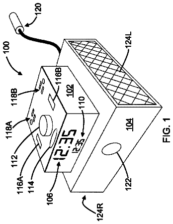
Alarm clock with charging ports
An alarm clock is provided that has a housing, one or more charging ports, an audio transducer, an alarm control device, a display, and a controller.
US 9,786,115 B2 · Assignee: UNIVERSAL ENTERTAINMENT CORPORATION · Inventors: Hirato; Jun et al.
Sheet 1 of 74 from the published document. All sheets in the USPTO PDF
There is provided a gaming machine capable of providing an effect for symbol display during a stop and/or rotation of a reel, by use of a totally non-conventional effect element, which is an angle of a line of sight to an outer circumferential surface of the reel. Reel strips M 32 each having symbols 501 are respectively disposed on outer circumferential surfaces of cylindrical reels M 31 each configured to be rotated with its cylinder central axis being held at a predetermined position. Each reel strip M 32 includes a color shifting layer M 321 configured to selectively reflect and transmit predetermined wavelengths of visible light depending on the incident angle.
1 of 74 drawing sheets so far from the published document, cropped to the drawing. Every sheet is in the USPTO PDF.
What the patent claimed, word for word. All of it is now free to use.
The present application claims priority from Japanese Patent Application Nos. 2013-194566 filed on Sep. 19, 2013, and 2014-103624 filed on May 19, 2014, the disclosure of which is herein incorporated by reference in its entirety. BACKGROUND OF THE INVENTION Field of the Invention
The present invention relates to a reel strip and a gaming machine.
Conventionally, as a gaming machine, there is a slot machine (for example, see Specification of U.S. Patent Application Publication No. 2004/0009807). Such a slot machine includes a plurality of reels each having a reel strip with a plurality of symbols. When a game is run, the plurality of reels are rotated and then stopped to rearrange the symbols, and based on the rearranged symbols, its game result is determined. In such a gaming machine, effects for the reels are provided by displaying effect images on a transparent liquid crystal panel disposed in front of the reels (for example, see U.S. Pat. No. 8,105,154).
In such a gaming machine, a backlight for illuminating the reel strip is disposed inside each reel to improve the visibility of the symbols. It has been general to provide an effect for the mechanical reel strips by changing the intensity and/or the color of the backlight.
In view of the above, an object of the present invention is to provide a gaming machine capable of providing an effect for symbol display during a stop and/or rotation of a reel, by use of a totally non-conventional effect element, which is an angle of a line of sight to an outer circumferential surface of the reel.
A reel strip according to an embodiment of the present invention has symbols placed thereon, and the reel strip is disposed on an outer circumferential surface of a cylindrical reel configured to be rotated with its cylinder central axis being held at a predetermined position. The reel strip includes a color shifting layer configured to selectively reflect and transmit predetermined wavelengths of visible light depending on an incident angle of the light.
In the above structure, the color shifting layer of the reel strip is configured to selectively reflect and transmit predetermined wavelengths of visible light depending on the incident angle of the light. Therefore, the colors of visible light viewed at different viewing angles to the outer circumferential surface of the reel are different from each other since the incident angles of the visible light, corresponding to the respective viewing angles, to the outer circumferential surface of the reel are different from each other. The reel is rotated while being held at the predetermined position, and therefore, as long as the viewing angle is maintained, the incident angle of visible light is also maintained. Accordingly, there is no change in the perceived color of visible light on the reel. Conventionally, an effect for symbol display has been provided by changing the intensity and/or the color of light applied to the reel formed of layers each configured to merely transmit and/or reflect light uniformly. However, the above structure makes it possible to provide an effect for symbol display during a stop and/or rotation of the reel, by use of a totally unconventional effect element, which is the angle of a line of sight (viewing angle) to the outer circumferential surface of the reel. As a result, the following effect is possible, for example: the appearance of the reel and/or the symbols perceived by a player is different that perceived by a person other than the player.
The reel strip according to an embodiment of the present invention may further include: a diffusion layer laminated at a position inward of the color shifting layer and configured to diffuse incident light to be outputted; and a symbol-printed layer laminated at a position outward of the color shifting layer, on which symbol-printed layer the placed symbols are printed.
A gaming machine according to an embodiment of the present invention includes: a reel including a reel strip provided on an outer circumferential surface of the reel, the reel strip having symbols placed thereon; and a reel drive mechanism configured to rotate the reel at a predetermined position to rearrange the symbols. The reel strip includes a color shifting layer configured to selectively reflect and transmit predetermined wavelengths of visible light depending on an incident angle of the light.
In the above structure, the color shifting layer of the reel strip is configured to selectively reflect and transmit predetermined wavelengths of visible light depending on the incident angle of the light. Therefore, the colors of visible light viewed at different viewing angles to the outer circumferential surface of the reel are different from each other since the incident angles of the visible light, corresponding to the respective viewing angles, to the outer circumferential surface of the reel are different from each other. The reel is rotated while held at the predetermined position, and therefore, as long as the viewing angle is maintained, the incident angle of visible light is also maintained. Accordingly, there is no change in the color of the reel perceived by the player. Conventionally, an effect for symbol display has been provided by changing the intensity and/or the color of light applied to the reel formed of layers each configured to merely transmit and/or reflect light uniformly. However, the above structure makes it possible to provide an effect for symbol display during a stop and/or rotation of the reel, by use of a totally unconventional effect element, which is the angle of a line of sight (viewing angle) to the outer circumferential surface of the reel. This enables, for example, an effect that a player and a person other than the player see the reel and/or the symbols differently from each other.
The gaming machine according to an embodiment of the present invention may further include: a display window through which the symbols on the reel strip are visible from the outside; a backlight unit configured to emit backlight illuminating light including the predetermined wavelengths of visible light from a position inside the reel toward a portion of the reel strip which portion is located within the display window; and, a front light unit configured to emit front light illuminating light including the predetermined wavelengths of visible light from a position outside the reel toward the reel strip.
In this structure, the backlight illuminating light and the front light illuminating light are applied to the reel strip at their respective incident angles, and they are reflected and transmitted in the manners corresponding to their respective incident angles. As a result, the external player sees visible light formed by combining transmitted light of the backlight illuminating light and reflected light of the front light illuminating light. Further, the display window is mainly lighted by the transmitted light of the backlight illuminating light, while the outside of the display window is mainly lighted by the reflected light of the front light illuminating light. This enables a gradation of colors over the range of visible light to be used as an effect for reel display and symbol display.
The gaming machine according to an embodiment of the present invention may further include a backlight control device configured to control an emission manner of the backlight illuminating light emitted from the backlight unit. The backlight unit may include a plurality of illuminating light sources arranged in a width direction and a longitudinal direction of the reel strip, with which light sources an amount of the emitted backlight illuminating light is adjustable to multiple levels; and the backlight control device may be configured to control the plurality of illuminating light sources individually.
In the above structure, it is possible to cause a change in the gradation of colors over the range of visible light produced by combining the reflected and transmitted light of the backlight illuminating light and the reflected and transmitted light of the front light illuminating light, by changing the emission manner of the backlight illuminating light using the backlight control device. This increases the freedom in the effect for reel display and symbol display.
The gaming machine according to an embodiment of the present invention may further include a front light control device configured to control an emission manner of the front light illuminating light emitted from the front light unit. The front light unit may include a plurality of illuminating light sources arranged in the width direction of the reel strip, with which light sources an amount of the emitted front light illuminating light is adjustable to multiple levels; and the front light control device may be configured to control the plurality of illuminating light sources individually.
In the above structure, it is possible to cause a change in the gradation of colors over the range of visible light is produced by combining the reflected and transmitted light of the backlight illuminating light and the reflected and transmitted light of the front light illuminating light, by changing the emission manner of the front light illuminating light using the front light control device. This increases the freedom in the effect for reel display and symbol display.
In the gaming machine according to an embodiment of the present invention, each of the illuminating light sources may be a full color light-emitting diode.
In the above structure, it is possible to easily emit various wavelengths of visible light including the predetermined wavelengths of visible light from a single light source.
In the gaming machine according to an embodiment of the present invention, the reel may have a cylindrical shape, and may be configured to be rotated with its cylinder central axis being held at the predetermined position by the reel drive mechanism, and the front light unit may be disposed at a position along a direction of rotation of the reel and outside the display window.
In the above structure, light emitted from the front light unit is applied to the reel strip at an incident angle falling within a range defined by a normal line and a tangent line to the reel strip. Thus, the incident angle of the light to the reel strip continuously varies within the ranges from 0 to 90 degrees as the location on the reel strip where the light is applied varies. This provides a continuous gradation of colors over the range of the reflected light. Therefore, the color of the symbols on the reel strip and the color of the region around each symbol vary with the rotation of the reel. Conventionally, there has been an effect of light-dark gradation in which, for example, the intensity of light from the front light unit is increased as the symbols are moved toward the outside of the display window with the rotation of the reel. However, there has not been realized an effect of a gradation of colors using the color shifting layer, but now, a totally new effect is available.
In the reel strip according to an embodiment of the present invention, the color shifting layer may be a color film of which color perceived by a viewer changes depending on a viewing angle.
In the reel strip according to an embodiment of the present invention, the color shifting layer may be a multilayer optical film having a plurality of layers each configured to selectively reflect specific wavelengths of light.
In the reel strip according to an embodiment of the present invention, the color shifting layer may have a characteristic that its reflection band shifts toward a shorter wavelength band and becomes narrower as the incident angle decreases.
In the reel strip according to an embodiment of the present invention, the color shifting layer may have a characteristic that when visible light is applied to the color shifting layer at an incident angle of 90 degrees, the color shifting layer transmits violet, blue, green, and longer-wavelength red light, while the color shifting layer reflects yellow, orange, and shorter-wavelength red light.
In the reel strip according to an embodiment of the present invention, the color shifting layer may have a characteristic that: when visible light is applied to the color shifting layer at an incident angle of 90 degrees, the color shifting layer transmits violet, blue, green, and longer-wavelength red light, while the color shifting layer reflects yellow, orange, and shorter-wavelength red light; and when visible light is applied to the color shifting layer at an incident angle of 60 degrees, the color shifting layer transmits violet, shorter-wavelength blue, yellow, orange, and red light, while the color shifting layer reflects longer-wavelength blue and green light.
The reel strip according to an embodiment of the present invention may further include a symbol-printed layer on which the symbols are printed. A picture pattern in various colors may be printed in a region of the symbol-printed layer which region is other than regions where the symbols are located; and the color shifting layer may be laminated in the region other than the regions where the symbols are located.
In the gaming machine according to an embodiment of the present invention, the color shifting layer may be a color film of which color perceived by a viewer changes depending on a viewing angle.
In the gaming machine according to an embodiment of the present invention, the color shifting layer may be a multilayer optical film having a plurality of layers each configured to selectively reflect specific wavelengths of light.
In the gaming machine according to an embodiment of the present invention, the color shifting layer may have a characteristic that its reflection band shifts toward a shorter wavelength band and becomes narrower as the incident angle decreases.
In the gaming machine according to an embodiment of the present invention, the color shifting layer may have a characteristic that when visible light is applied to the color shifting layer at an incident angle of 90 degrees, the color shifting layer transmits violet, blue, green, and longer-wavelength red light, while the color shifting layer reflects yellow, orange, and shorter-wavelength red light.
In the gaming machine according to an embodiment of the present invention, the color shifting layer may have a characteristic that: when visible light is applied to the color shifting layer at an incident angle of 90 degrees, the color shifting layer transmits violet, blue, green, and longer-wavelength red light, while the color shifting layer reflects yellow, orange, and shorter-wavelength red light; and when visible light is applied to the color shifting layer at an incident angle of 60 degrees, the color shifting layer transmits violet, shorter-wavelength blue, yellow, orange, and red light, while the color shifting layer reflects longer-wavelength blue and green light.
In the gaming machine according to an embodiment of the present invention, the reel strip may include a symbol-printed layer on which the symbols are printed; a picture pattern in various colors may be printed in a region of the symbol-printed layer which region is other than regions where the symbols are located; and the color shifting layer may be laminated in the region other than the regions where the symbols are located.
In the present invention, it is possible to provide an effect for symbol display during a stop and/or rotation of a reel, by use of a totally non-conventional effect element, which is an angle of a line of sight to an outer circumferential surface of the reel.
FIG. 1 is an explanatory diagram showing an operation of a gaming machine.
FIG. 2 is a graph showing an example of reflection and transmission characteristics of a color shifting layer to incident light at an incident angle of 90 degrees.
FIG. 3 is a graph showing an example of reflection and transmission characteristics of the color shifting layer to incident light at an incident angle of 60 degrees.
FIG. 4 is an explanatory diagram showing a relationship between a reel and a viewing angle of a player.
FIG. 5 is an explanatory diagram showing a function flow of the gaming machine.
FIG. 6 is an explanatory diagram showing a function flow of an external controller.
FIG. 7 is an explanatory diagram showing an overall structure of a game system.
FIG. 8 is a front view of a slot machine in the gaming machine.
FIG. 9 is an exploded perspective view of a reel device and a reel cover.
FIG. 10 is a perspective view of the reel device.
FIG. 11 is a front view of the reel cover.
FIG. 12 is an exploded perspective view of the reel device and the reel cover.
FIG. 13 is an exploded view of the reel device and the reel cover.
FIG. 14 is an exploded perspective view of a part of the reel device and a part of the reel cover.
FIG. 15 is an exploded view of the reel device and the reel cover.
FIG. 16 is a front view of the reel cover.
FIG. 17 is an explanatory diagram showing layers of a reel strip.
FIG. 18 is an explanatory diagram showing the layers of the reel strip.
FIG. 19 is an explanatory diagram showing a section of the reel strip.
FIG. 20 is a front view of a reel frame and a backlight unit.
FIG. 21 is an explanatory diagram showing a structure of a top box decoration unit.
FIG. 22 is an explanatory diagram showing a structure of a topper display device.
FIG. 23 is an explanatory diagram showing a structure of a front portion of the topper display device.
FIG. 24 is an explanatory diagram showing a structure of a side portion of the topper display device.
FIG. 25 is an explanatory diagram showing an internal structure of the topper display device.
FIG. 26 is an explanatory diagram showing the internal structure of the topper display device.
FIG. 27 is an exploded perspective view of the topper display device.
FIG. 28 is a side view of a first diffusion member.
FIG. 29 is a side view of a second diffusion member.
FIG. 30 is a side view of a third diffusion member.
FIG. 31 is an explanatory diagram showing diffusion of light by the topper display device.
FIG. 32 is an explanatory diagram showing internal reflection of light in the topper display device.
FIG. 33 is an electric block diagram of the slot machine.
FIG. 34 is a block diagram showing a process of a main game program run by a motherboard.
FIG. 35 is an exemplary symbol code table used for designating symbols on outer circumferential surfaces of reel units.
FIG. 36 is a diagram showing a state in which a predetermined number or more of trigger symbols are arranged on a symbol matrix, and showing an example of a trigger condition for shifting to a bonus game.
FIG. 37 is a diagram showing paylines in the gaming machine of the first embodiment.
FIG. 38 is an exemplary normal game symbol determination table.
FIG. 39 is an exemplary bonus game symbol determination table.
FIG. 40 is an exemplary bonus game symbol determination table.
FIG. 41 is an exemplary bonus game symbol determination table.
FIG. 42 is an exemplary bonus game symbol determination table.
FIG. 43 is an exemplary bonus game symbol determination table.
FIG. 44 is an exemplary bonus game symbol determination table.
FIG. 45 is an exemplary bonus game symbol determination table.
FIG. 46 is an exemplary bonus game symbol determination table.
FIG. 47 is an exemplary bonus game symbol determination table.
FIG. 48 is an exemplary bonus game symbol determination table.
FIG. 49 is an exemplary payout table.
FIG. 50 is an exemplary symbol determination table random determination table.
FIG. 51 is a diagram showing an example of image display on a VFD of the gaming machine.
FIG. 52 is a diagram showing an example of image display on an upper image display panel.
FIG. 53 is a diagram showing an example of image display on the upper image display panel.
FIG. 54 is a diagram showing an example of image display on a display window and on the VFD.
FIG. 55 is a diagram showing an example of image display on the display window and on the VFD.
FIG. 56 is a diagram showing an example of image display on the upper image display panel.
FIG. 57 is a diagram showing an example of image display on the upper image display panel.
FIG. 58 is a diagram showing an example of image display on the upper image display panel.
FIG. 59 is a diagram showing an example of image display on the display window and on the VFD.
FIG. 60 is a diagram showing an example of image display on the upper image display panel.
FIG. 61 is a diagram showing an example of image display on the display window and on the VFD.
FIG. 62 is a diagram showing an example of image display on the display window and on the VFD.
FIG. 63 is a diagram showing an example of image display on the upper image display panel.
FIG. 64 is a diagram showing an example of image display on the upper image display panel.
FIG. 65 is a diagram showing an example of image display on the upper image display panel.
FIG. 66 is a diagram showing an example of image display on the upper image display panel.
FIG. 67 is a diagram showing an example of image display on the display window and on the VFD.
FIG. 68 is a diagram showing an example of image display on the upper image display panel.
FIG. 69 is a diagram showing an example of image display on the upper image display panel.
FIG. 70 is a diagram showing an example of image display on the display window and on the VFD.
FIG. 71 is a diagram showing an example of image display on the upper image display panel.
FIG. 72 is a diagram showing an example of image display on the upper image display panel.
FIG. 73 is a diagram showing an example of an indication effect on the display window.
FIG. 74 is a diagram showing an example of the indication effect on the display window.
FIG. 75 is a table showing the relationship between a remaining count-up number and the number of seconds.
FIG. 76 is a table showing the relationship between a multiplying factor and the number of seconds.
FIG. 77 is a flowchart showing a general process executed in the gaming machine of the first embodiment.
FIG. 78 is a flowchart showing a normal game process.
FIG. 79 is a flowchart showing details of a symbol determination process.
FIG. 80 is a flowchart showing a bonus game process.
FIG. 81 is an explanatory diagram showing layers of a reel strip of a modification.
FIG. 82 is an explanatory diagram showing the layers of the reel strip of the modification.
FIG. 83 is a side view of the reel strip of the modification with its partial exploded sectional views.
FIG. 84 is a perspective view of a three-dimensional symbol portion of the modification.
(Overview of Gaming Machine)
As shown in FIG. 1 , in a gaming machine of the present embodiment, reel strips M 32 each having symbols 501 placed thereon are respectively disposed on outer circumferential surfaces of cylindrical reels M 32 each configured to be rotated with its cylinder central axis being held at a predetermined position. Each reel strip M 32 includes a color shifting layer M 321 configured to selectively reflect and transmit predetermined wavelengths of visible light depending on an incident angle of the light. That is, the gaming machine includes: the reels M 31 each including the reel strip M 32 provided on the outer circumferential surface of the reel, the reel strip having the symbols 501 placed thereon; and a reel device M 1 (a reel drive mechanism) configured to rotate each reel M 31 at the predetermined position to rearrange the symbols 501 . Each reel strip M 32 includes the color shifting layer M 321 configured to selectively reflect and transmit predetermined wavelengths of visible light depending on an incident angle of the light. Note that the following description assumes that the gaming machine is a multiple-player type gaming machine including a plurality of slot machines 10 ; however, the gaming machine may be a single slot machine 10 intended for a single player.
To be more specific, each of the slot machines 10 functioning as the gaming machine includes: the reels M 31 each having the reel strip M 32 with the plurality of symbols 501 , the reel strip M 32 provided on the entire circumference of the corresponding reel M 31 ; a display window 150 through which the symbols 501 on each reel strip M 32 are visible from the outside; a backlight unit M 7 configured to emit backlight illuminating light including the predetermined wavelengths of visible light from a position inside the reels M 31 toward a portion of the reel strips M 32 which is located within the display window 150 ; and a front light unit R 1 configured to emit front light illuminating light including the predetermined wavelengths of visible light from positions outside the reels M 31 toward the reel strips M 32 .
With the above structure, the color shifting layer M 321 of each reel strip M 32 is configured to selectively reflect and transmit the predetermined wavelengths of visible light depending on the incident angle of the light. The colors of visible light viewed at different angles of lines of sight (at different viewing angles) to the outer circumferential surfaces of the reels M 31 are different from each other since the incident angles of visible light, corresponding to the respective viewing angles, to the outer circumferential surfaces of the reels M 31 are different from each other. Each reel M 31 is rotated while being held at the predetermined position, and therefore, as long as the viewing angle is maintained, the incident angle of visible light is maintained. Accordingly, there is no change in visible light coming from the reels M 31 . Conventionally, the effect for display of the symbols 501 has been provided by changing the intensity and/or the color of light emitted to the reels M 31 each formed of one or more layers configured to merely transmit and/or reflect light uniformly. However, the above structure makes it possible to provide an effect for display of the symbols 501 during a stop and/or rotation of the reels M 31 , by use of a totally unconventional effect element, which is an angle of a line of sight (viewing angle) to the outer circumferential surfaces of the reels M 31 . As a result, the following effect is possible, for example: the appearance of each reel M 31 and/or the symbols 501 perceived by a player is different that perceived by a person other than the player.
As described above, the color shifting layer M 321 is a color film of which color perceived by a viewer changes depending on a viewing angle. The color shifting layer M 321 of the present embodiment is a multilayer optical film having a plurality of layers each configured to selectively reflect specific wavelengths of light. The color shifting is caused, for example, by interference of light reflected by the layers. As the color shifting layer M 321 , a film described in Japanese Unexamined Patent Publication No. 2011-085959 may be used, for example.
Now, specific description will be given for the display state on the reels M 31 of the present embodiment. The following description will be given on an assumption that visible light is white light having a wavelength range of 380 nm to 780 nm; however, the visible light is not limited to this. As shown in FIG. 2 , the color shifting layer M 321 has the following characteristic: when visible light is applied to the color shifting layer M 321 at an incident angle of 90 degrees, the color shifting layer M 321 transmits violet (approximately 380 nm to 450 nm), blue (approximately 450 nm to 495 nm), green (approximately 495 nm to 570 nm), and longer-wavelength red (approximately 620 nm to 780 nm) light; while the color shifting layer M 321 reflects yellow (approximately 570 nm to 590 nm), orange (approximately 590 nm to 620 nm), and shorter-wavelength red light. Further, as shown in FIG. 3 , the color shifting layer has a characteristic that when visible light is applied thereto at an incident angle of 60 degrees, the color shifting layer M 321 transmits violet, shorter-wavelength blue, yellow, orange, and red light, while the color shifting layer M 321 reflects longer-wavelength blue and green light. Thus, the color shifting layer M 321 has a characteristic that its reflection band shifts toward a shorter wavelength band (toward the blue light band) and becomes narrower, as the incident angle decreases. In other words, the color shifting layer M 321 has a characteristic that longer wavelength colors such as yellow, orange, and red are perceived when the incident angle decreases.
The present embodiment is configured so that the emission manner (amount of light, color, time interval between emissions, timing of emission, and the like) of backlight illuminating light emitted from the backlight unit M 7 is controllable, and so that the emission manner (amount of light, color, time interval between emissions, timing of emission, and the like) of front light illuminating light emitted from the front light unit R 1 is controllable. When the amount of the backlight illuminating light is decreased, for example, (or when the amount of the front light illuminating light is increased), light reflected by the color shifting layers M 321 is greater on the reel strips M 32 , with the result that the longer-wavelength colors such as yellow, orange, and red are highly perceived by the player. Meanwhile, when the amount of the front light illuminating light is decreased (or when the amount of the backlight illuminating light is increased), light transmitted by the color shifting layer M 321 is greater on the reel strips M 32 , with the result that shorter-wavelength colors such as violet, blue, and green are highly perceived by the player.
Further, if there is a person other than the player next to the player playing the slot machine 10 , the longer-wavelength colors of such as yellow, orange, and red are highly perceived as the person other than the player gets away from the player (as the viewing angle to the reel strip M 32 decreases). That is, the person other than the player perceives that the longer wavelength-colors of the reel strips M 32 fade as the person gets closer to the slot machine 10 .
Further, on each reel M 31 , the reel strip M 32 is annularly placed as shown in FIG. 1 . Therefore, it is perceived as if each reel M 31 has a gradation of colors. Now, description will be given for an exemplary case where a target point B on the reel M 31 which point is leveled with the center of the reel M 31 and a target point C on the reel M 31 which point is displayed on an upper area of the display window 150 are viewed from a viewing position A leveled with the center of the reel M 31 , as shown in FIG. 4 . The backlight unit M 7 emits backlight illuminating light 903 including the predetermined wavelengths of visible light from the position inside the reel M 31 toward a portion of the reel strip M 32 which is located within the display window 150 . Further, the front light unit R 1 emits front light illuminating light 904 including the predetermined wavelengths of visible light toward the reel strip M 32 from positions outside the reel M 31 and above and below the display window 150 .
Since the front light illuminating light 904 is emitted from the positions above and below the display window 150 , light traveling from the target point B to the viewing position A is mainly constituted by backlight transmitted light 903 a which is the backlight illuminating light 903 transmitted by the reel strip M 32 . Accordingly, the color of the target point B of the reel M 31 perceived at the viewing position A is greatly affected by the color of light transmitted by the color shifting layer M 321 . Meanwhile, light traveling from the target point C to the viewing position A is mainly constituted by front light reflected light 904 a which is the front light illuminating light 904 reflected by the reel strip M 32 . Accordingly, the color of the target point C of the reel M 31 perceived at the viewing position A is greatly affected by the color of light reflected by the color shifting layer M 321 . Thus, when the player sees each reel M 31 through the display window 150 , the color of each reel M 31 changes, in directions from the center to the upper and the lower ends of the reel M 31 , from a color affected by the color of light transmitted by the color shifting layer M 321 to a color affected by the color of light reflected by the color shifting layer M 321 . This way, it is perceived as if the reels M 31 seen through the display window 150 have a gradation of colors over the range of visible light.
As described above, each reel strip M 32 has the color shifting layer M 321 configured to selectively reflect and transmit predetermined wavelengths of visible light depending on an incident angle of the light, and this allows the reels M 31 to have the following functions. The reels M 31 have a function of changing the color of the reels M 31 through adjustment of the amount of the backlight illuminating light and/or the front light illuminating light. Further, the reels M 31 have a function of causing the player and a person other than the player to perceive different colors of the reels M 31 . Furthermore, the reels M 31 have a function of causing the player to perceive as if the reels M 31 have a gradation of colors over the range of visible light.
The slot machine 10 with the above described structure is provided to a multiple-player type gaming machine 300 , as shown in FIG. 7 . The gaming machine 300 includes a plurality of slot machines 10 each serving as the gaming terminal having the reel device M 1 , which are connected to a center controller 200 in such a manner that data communication is possible. The gaming machine 300 enables running of a basic game such as a slot game independently in each of the slot machines 10 , and enables running of a common game by synchronizing the slot machines 10 with each other.
Note that the connection between the slot machine 10 and the center controller 200 may be wired or wireless, or may be a combination of these. The unit of a bet amount may be a national or local currency such as Dollar, Yen, and Euro, or a game point used only in the field or halls having the gaming machine 300 .
More specifically, the gaming machine 300 has: an input device configured to enable an input from outside; the plurality of slot machines 10 each configured to run a basic game independently of another and having a terminal controller programmed to run various processes for conducting a common game which is run in the slot machines 10 ; and a center controller 200 connected to and in communication with the slot machines 10 and programmed to run various processes.
The terminal controller of the gaming machine 300 is configured to execute at least: a process of running a basic game upon an input of a start operation through the input device; a process of running a common game upon reception of a game start command from the center controller 200 ; and a process of determining a game result of the common game, based on game result information from the center controller 200 .
Here, the “common game” here is a sub game which is different from a basic game (main game) which is an essential game of the gaming machine 300 . The common game is run in parallel to the basic game or during a period in which the basic game is stopped. For example, the common game may be craps game, baseball game, and soccer game.
As shown in FIG. 5 , the center controller 200 of the gaming machine 300 is configured to execute at least: a process of outputting a game start command to a slot machine 10 satisfying a game running condition at a predetermined timing; a process of determining a game result of the common game; a process of outputting the game result determined as the game result information to the slot machine 10 .
Here, the “game running condition” is a condition for enabling participation into the common game. For example, the condition may be an accumulated value of the bet amount on the basic game being the minimum bet amount or more, or the number of games in the basic game being a minimum number of times or more. Note that the “game running condition” can be satisfied by the player based on his/her will, immediately before the common game is started. For example, if the game running condition is not satisfied due to the accumulated value of the bet amount of the basic game falling short of the minimum bet amount, the player may satisfy the game running condition by paying a difference between the minimum bet amount and the accumulated value of the bet amount before the common game is started, or by paying an amount to meet the predetermined condition. Further, if the condition is not satisfied due to the number of basic games played falling short, the player may satisfy the game running condition by paying an amount to compensate the shortage, or by paying an amount to meet the predetermined condition.
Further, the predetermined timing for outputting the game start command is a timing at which the common game start condition is satisfied in any one of the slot machine 10 . The “common game start condition” relates to the accumulated bet amount information or an accumulated number of basic games. The present embodiment deals with a case where the gaming machine 300 having the center controller 200 apart from the slot machine 10 ; however, the present invention is not limited to this. The gaming machine 300 may be arranged such that one or more slot machines 10 have the function of the center controller 200 and the slot machines 10 are connected to be able to communicate with one another.
The slot machine 10 above is a kind of the gaming terminals in the gaming machine 300 . Although the present embodiment deals with the slot machine 10 as an example of the gaming terminal, the disclosure is not limited to this and any type of device having a terminal controller that is able to independently run a basic game may be used as the gaming terminal.
The basic game in the present embodiment is run by the slot machine 10 . The basic game is a slot game of rearranging a plurality of symbols 501 . The basic game is not limited to the slot game but is any type of games capable of being independently run at a gaming terminal such as the slot machine 10 .
Rearrangement of symbols 501 in the slot game is executed by the reel device M 1 (symbol display device). The slot game includes a process of running a normal game of rearranging symbols 501 on the reel device M 1 on condition that a gaming value is bet and awarding a normal payout based on the rearranged symbols 501 , and a process of running a bonus game of rearranging symbols 501 with the assumption that the payout rate is higher than that of the normal game when the rearranged symbols 501 achieve a predetermined condition and awarding a bonus payout based on the rearranged symbols 501 .
The description continues in the full USPTO document.
About 6,753 words. The USPTO PDF has it with every drawing.
Fees are due 3.5, 7.5 and 11.5 years after grant. This patent expired on October 10, 2025, so the fee marked "not paid" was the one that went unpaid.
REEL STRIP AND GAMING MACHINE
Filed Sep 2014 · published Mar 2015Reel strip and gaming machine
Filed Sep 2014 · granted Oct 2017Earlier publications, parents and continuations. None of them can still be enforced, or this patent would not be listed.
Prior art cited by the examiner or applicant. Useful when you check your own idea for novelty.
Everything on this page comes from the documents linked above.


