Cross-reference to related applications
This application is based on and claims priority under 35 USC 119 from Japanese Patent Application No. 2015-019432 filed Feb. 3, 2015.
Background
The present invention relates to an image forming apparatus.
Summary
According to an aspect of the invention, there is provided an image forming apparatus including a first forming unit that forms a first image with a substantially flat toner containing a substantially flat metal pigment on a moving movable body; a second forming unit that forms a second image with a substantially non-flat toner on the movable body; a transfer unit that forms a nip with the movable body while circulating and transfers the first image and the second image on a medium transported to the nip; a removing unit that includes a rotational body and removes the toners adhering to the transfer unit, the rotational body having an axis and being configured to rotate around the axis; and a controller that, if the controller causes the first forming unit to form the first image, stops the rotation of the rotational body around the axis.
Brief description of the drawings
Exemplary embodiments of the present invention will be described in detail based on the following figures, wherein:
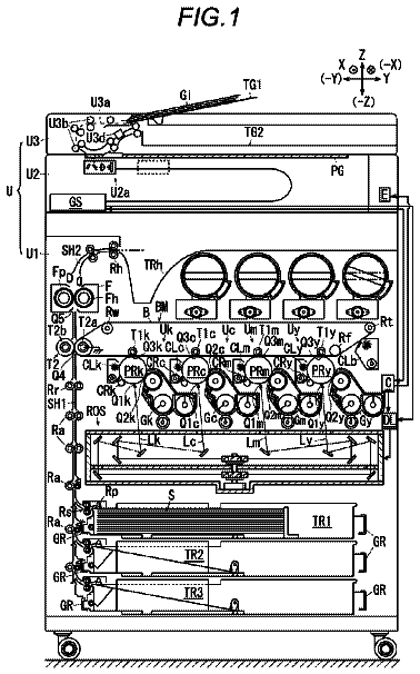
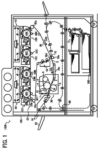
FIG. 1 is schematic view (front view) of an image forming apparatus according to a first exemplary embodiment;
FIG. 2 is a schematic view (front view) of a toner image forming unit configuring the image forming apparatus according to the first exemplary embodiment;
FIG. 3 is a schematic view of a peripheral area of a second transfer unit of a transfer device configuring the image forming apparatus according to the first exemplary embodiment;
FIG. 4 is a schematic view (cross-sectional view) of a toner particle of a flat toner that is used by the image forming apparatus according to the first exemplary embodiment;
FIG. 5 is a schematic view (cross-sectional view) of a toner particle of a non-flat toner that is used by the image forming apparatus according to the first exemplary embodiment;
FIG. 6 is a schematic view showing a state in which a toner image and a non-transfer image are held by a transfer belt in the image forming apparatus according to the first exemplary embodiment;
FIGS. 7A and 7B are each an illustration showing a flat toner held on a transfer belt of the image forming apparatus according to the first exemplary embodiment, FIG. 7A being a schematic view showing a flat toner configuring a toner image within a dotted-line area VIIA in FIG. 1 , FIG. 7B being a schematic view showing a flat toner configuring a toner image within a dotted-line area VIIB in FIG. 1 ;
FIG. 8 is a flowchart when a controller configuring the image forming apparatus according to the first exemplary embodiment controls the second transfer unit during a transfer operation;
FIG. 9 is a schematic view showing a predetermined condition of the controller in the flowchart in FIG. 8 , in the image forming apparatus according to the first exemplary embodiment;
FIG. 10 is a graph showing a test result that serves as the basis of the predetermined condition in FIG. 9 ;
FIG. 11A is a schematic view showing an image on a medium formed by an image forming apparatus according to a comparative exemplary embodiment, FIG. 11B is a partial cross-sectional view taken along line XIB-XIB in FIG. 11A , and FIG. 11C is a partial cross-sectional view taken along line XIC-XIC in FIG. 11A ;
FIG. 12 is a flowchart when a controller configuring an image forming apparatus according to a second exemplary embodiment controls a second transfer unit during a transfer operation;
FIG. 13 is a schematic view of a peripheral area of a second transfer unit of a transfer device configuring an image forming apparatus according to a third exemplary embodiment;
FIG. 14 is a flowchart when a controller configuring the image forming apparatus according to the third exemplary embodiment controls the second transfer unit during a transfer operation;
FIG. 15 is a schematic view of a peripheral area of a second transfer unit of a transfer device configuring an image forming apparatus according to a fourth exemplary embodiment;
FIG. 16 is a flowchart when a controller configuring the image forming apparatus according to the fourth exemplary embodiment controls the second transfer unit during a transfer operation; and
FIG. 17 is a flowchart when a controller configuring an image forming apparatus according to other exemplary embodiment controls a second transfer unit during a transfer operation.
Detailed description
Overview
Exemplary embodiments for implementing the invention (hereinafter, referred to as exemplary embodiments) are described below. In the description of the exemplary embodiments, first to fourth exemplary embodiments are provided. In the following description, directions indicated by arrow X and arrow −X in the drawings represent an apparatus width direction, and directions indicated by arrow Y and arrow −Y in the drawings represent an apparatus height direction. Also, directions (arrow Z and arrow −Z directions) orthogonal to the apparatus width direction and the apparatus height direction represent an apparatus depth direction. First Exemplary Embodiment
This exemplary embodiment is described below with reference to the drawings. First, a configuration of an image forming apparatus 10 (see FIG. 1 ) according to this exemplary embodiment is described. Then, an image forming operation of the image forming apparatus 10 of this exemplary embodiment is described. Then, effects of this exemplary embodiment are described.
Configuration of Image Forming Apparatus
First, a general configuration of the image forming apparatus 10 is described, and then, major portions (a transfer device 30 , a second transfer unit 36 (see FIG. 3 ) configuring the transfer device 30 , and a toner (see FIGS. 4 and 5 ) used by the image forming apparatus 10 ) are described.
General Configuration of Image Forming Apparatus
As shown in FIG. 1 , the image forming apparatus 10 is an electrophotographic apparatus including a toner image forming unit 20 , a transfer device 30 , a transport device 40 , a fixing device 50 , a controller 60 , and a power supply PS. In the image forming apparatus 10 of this exemplary embodiment, an example of a medium P on which an image may be formed is a cut sheet.
Toner Image Forming Unit
The toner image forming unit 20 has a function of forming a toner image G 1 (see FIGS. 1 and 6 ) and a non-transfer image G 2 (see FIG. 6 ) held on a transfer belt TB (described later), which configures the transfer device 30 , by executing respective processes of electric charge, exposure, and development. In this exemplary embodiment, the toner image G 1 represents a toner image to be second transferred on a medium P. In contrast, the non-transfer image G 2 is not a toner image to be second transferred, but the non-transfer image G 2 is a toner image to be formed for maintaining an electrically charged state etc. of respective toners MT and NT (for example, for restricting excessive electric charge of the toners MT and NT) housed in developing devices 28 G, 28 Y, 28 M, 28 C, and 28 K (described later). For example, the image forming apparatus 10 of this exemplary embodiment is configured such that the non-transfer image G 2 is first transferred on a portion of the transfer belt TB which does not contact the medium P at a nip N 2 (described later) of the transfer belt TB, and the non-transfer image G 2 is removed by a blade 38 (described later) (see FIG. 6 ). In the following description, the toners MT and NT are described as a toner T unless otherwise the toner MT and the toner NT are particularly required to be distinguished from one another.
The toner image forming unit 20 includes single-color units 21 G, 21 Y, 21 M, 21 C, and 21 K that form toner images G 1 of different colors (G (gold), Y (yellow), M (magenta), C (cyan), K (black)). The single-color units 21 G, 21 Y, 21 M, 21 C, and 21 K have similar configurations except the colors of the respectively formed toner images G 1 . Hereinafter, in the specification and drawings, the alphabets (G, Y, M, C, K) of the single-color units 21 G, 21 Y, 21 M, 21 C, and 21 K are omitted unless otherwise the single-color units 21 G, 21 Y, 21 M, 21 C, and 21 K and their components are required to be distinguished from one another. The single-color unit 21 G forms a toner image G 1 and a non-transfer image G 2 with a flat or substantially flat toner MT (hereinafter, referred to as toner MT, see FIG. 4 ), which is described later, on the transfer belt TB (described later). The single-color units 21 other than the single-color unit 21 G each form a toner image G 1 and a non-transfer image G 2 with a non-flat or substantially non-flat toner NT (hereinafter, referred to as toner NT, see FIG. 5 ), which is described later, on the transfer belt TB. The toner MT and the toner NT of this exemplary embodiment each have, for example, negative polarity (average of charge amount distribution is negative). The single-color unit 21 G is an example of a first forming unit, and the single-color units 21 other than the single-color unit 21 G are each an example of a second forming unit. Also, the toner image G 1 formed by the single-color unit 21 G is an example of a first image, and the toner image G 1 formed by each of the single-color units 21 other than the single-color unit 21 G is an example of a second image.
As shown in FIGS. 1 and 2 , each single-color unit 21 includes a photoconductor 22 , a charging device 24 , an exposure device 26 , a developing device 28 , and a first transfer roller 29 . The photoconductor 22 is cylindrical, and its axis (representing the axis of the photoconductor 22 ) is arranged along the apparatus depth direction. The first transfer roller 29 forms a nip N 1 with the photoconductor 22 with the transfer belt TB interposed therebetween. The charging device 24 electrically charges the photoconductor 22 , the exposure device 26 exposes the photoconductor 22 rotating around its axis, to light, and the developing device 28 develops the toner image G 1 and the non-transfer image G 2 . Thus, each single-color unit 21 forms the toner image G 1 and the non-transfer image G 2 on the photoconductor 22 . Also, a first transfer voltage (voltage with positive polarity) is applied from the power supply PS to each first transfer roller 29 , and hence the first transfer roller 29 first transfers the toner image G 1 and the non-transfer image G 2 formed on the photoconductor 22 , on the moving (circulating) transfer belt TB at the nip N 1 . The exposure device 26 forms, for example, a latent image on the photoconductor 22 with a minimum exposure dot corresponding to 1200 dpi×1200 dpi (about 21 μm×about 21 μm). In FIG. 1 , the reference signs for the components of the single-color units 21 other than those of the single-color unit 21 K are omitted.
Transfer Device
The transfer device 30 has a function of second transferring the toner images G 1 and the non-transfer image G 2 of the respective colors formed by the respective single-color units 21 and first transferred at the nips N 1 , on a medium P transported to a nip N 2 (described later). The configuration of the transfer device 30 is described later.
Transport Device
The transport device 40 has a function of transporting a medium P. If image formation is executed on plural media P during an image forming operation, the transport device 40 transports the plural media P at predetermined intervals interposed among the continuously transported media P.
Fixing Device
The fixing device 50 has a function of applying heat and pressure at a nip N 3 to the toners T configuring the toner images G 1 of the respective colors second transferred on the medium P by the transfer device 30 , and hence fixing the toners T to the medium P. The fixing device 50 includes a heating portion 50 A and a pressing portion 50 B.
Controller
The controller 60 has a function of controlling respective units other than the controller 60 configuring the image forming apparatus 10 .
The controller 60 receives image data from an external device (not illustrated). The controller 60 which has received the image data controls the respective units other than the controller 60 configuring the image forming apparatus 10 by following, for example, a flowchart in FIG. 8 . The controller 60 that executes control shown in the flowchart in FIG. 8 is described in detail in the description for an image forming operation of the image forming apparatus 10 . In this section, a predetermined condition in step S 210 in the flowchart in FIG. 8 is described. When the controller 60 receives image data from an external device, the controller 60 receives other data (for example, data indicating the number of media P, on which images are formed), from the external device. Also, the controller 60 causes the image forming apparatus 10 to execute the image forming operation in accordance with job data (data containing image data and data indicating the number of media P, or command).
If the controller 60 determines that a toner image G 1 with a gold-color toner MT satisfies a predetermined condition (if the controller 60 determines YES), the controller 60 causes the image forming apparatus 10 to execute an image forming operation in a special mode. In contrast, if the controller 60 determines that the condition is not satisfied (if the controller 60 determines NO) in determining step S 210 , the controller 60 causes the image forming apparatus 10 to execute an image forming operation in a normal mode. The specific contents of the special mode and the normal mode are described later.
Predetermined Condition
For example, as shown in FIG. 9 , the predetermined condition uses a ratio of a formation width of the toner MT (the maximum width in which the toner MT is formed) with respect to the width of a medium P, and an area coverage [%] of the toner MT as parameters. In this exemplary embodiment, it is assumed that the predetermined condition is satisfied if the ratio of the formation width of the toner MT with respect to the width of the medium P on which image formation is actually executed in accordance with job data is ⅔ or larger (1 or smaller) and the area coverage of the toner MT is 95% or higher (100% or lower) (if the toner image G 1 is included in a region A 1 in FIG. 9 ). The area coverage of the toner MT represents the percentage of the pixels in the axial direction of the photoconductor 22 G that is exposed to light by the exposure device 26 G (the pixels in the axial direction of the photoconductor 22 G having the toner image G 1 with the toner MT that is developed by the developing device 28 ) with respect to the pixels included in the formation width of the toner MT when the minimum exposure dot formed by the exposure device 26 G on the photoconductor 22 G is one pixel. For example, if the area coverage of the toner MT is 100%, the toner MT is developed and transferred in all pixels included in the formation width of the toner MT. Also, if the area coverage of the toner MT is 50%, the toner MT is developed and transferred in half of pixels included in the formation width of the toner MT. In this exemplary embodiment, the basis of the determination that the predetermined condition is satisfied if the toner image G 1 is included in the region A 1 in FIG. 9 is described later.
The above description is for the general configuration of the image forming apparatus 10 of this exemplary embodiment.
Configuration of Major Portions of Image Forming Apparatus
Next, the transfer device 30 , the second transfer unit 36 configuring the transfer device 30 , and the toners MT and NT used in the image forming apparatus 10 being major portions of the image forming apparatus 10 are described with reference to the drawings.
Transfer Device
As shown in FIG. 1 , the transfer device 30 includes the transfer belt TB, a driving roller 32 , a tension roller 34 , the second transfer unit 36 , and a blade 38 .
Transfer Belt, Driving Roller, and Tension Roller
The transfer belt TB is endless. The driving roller 32 is driven by a driving source (not illustrated), and moves the transfer belt TB in the arrow R direction while rotating around its axis. The tension roller 34 presses the transfer belt TB from the inner periphery side, and gives a tension to the transfer belt TB. With the above-described configuration, the toner images G 1 and the non-transfer images G 2 of the respective colors formed by the respective single-color units 21 are first transferred on the transfer belt TB while the transfer belt TB moves in the arrow R direction. The transfer belt TB causes the toner images G 1 and the non-transfer images G 2 of the respective colors to reach the nip N 2 while being held on the outer periphery. The transfer belt TB is an example of a movable body.
Second Transfer Unit
The second transfer unit 36 has a function of second transferring the toner images G 1 of the respective colors held on the transfer belt TB, on a medium P transported by the transport device 40 . As shown in FIGS. 1 and 3 , the second transfer unit 36 includes a second transfer portion 70 , a backup roller 80 (hereinafter, referred to as BUR 80 ), and a removing unit 90 .
Second Transfer Portion and BUR
The second transfer portion 70 includes a conductive roller 72 , a tension roller 74 , and a conductive belt CB. The conductive belt CB is an example of a transfer unit.
The conductive belt CB has a function of forming the nip N 2 with the transfer belt TB while the conductive belt CB circulates, and transferring a toner image G 1 on a medium P transported to the nip N 2 by the transport device 40 . The conductive roller 72 includes a shaft 72 A, and a cylindrical conductive layer 72 B. The conductive roller 72 is driven by a driving source (not illustrated) and rotates around its axis. The conductive belt CB is endless, and is wound around the cylindrical conductive layer 72 B. The tension roller 74 presses the conductive belt CB from the inner periphery side, and gives a tension to the conductive belt CB. With the above-described configuration, in the second transfer portion 70 , the conductive belt CB circulates when the conductive roller 72 rotates around its axis. The shaft 72 A of the conductive roller 72 is grounded.
As shown in FIGS. 1 and 3 , the BUR 80 is arranged at the opposite side (upper side) of the second transfer portion 70 with the transfer belt TB interposed therebetween. Also, the BUR 80 causes the conductive belt CB and the transfer belt TB to form the nip N 2 at a position offset with respect to the conductive roller 72 .
The BUR 80 includes a shaft 80 A, and a cylindrical conductive layer 80 B. A voltage is applied from the power supply PS (see FIG. 1 ) to the shaft 80 A of the BUR 80 . To be specific, a second transfer voltage (voltage with negative polarity) is applied from the power supply PS to the BUR 80 when a medium P passes through the nip N 2 . Consequently, the conductive belt CB forms an electric field for second transferring the toner image G 1 on the medium P at the nip N 2 together with the transfer belt TB. Also, a voltage with positive polarity is applied from the power supply PS to the BUR 80 before and after the medium P passes through the nip N 2 . Consequently, the conductive belt CB forms an electric field for causing the transfer belt TB to hold the non-transfer image G 2 at the nip N 2 together with the transfer belt TB.
With the above-described configuration, the conductive belt CB forms the nip N 2 together with the transfer belt TB while circulating, and transfers the toner image G 1 on the transported medium P in a period in which the medium P passes through the nip N 2 . Also, the conductive belt CB forms the nip N 2 together with the transfer belt TB while circulating, and allows the transfer belt TB to pass through the nip N 2 while the transfer belt TB holds the non-transfer image G 2 before and after the medium P passes through the nip N 2 .
Removing Unit
The removing unit 90 has a function of removing a toner T adhering to the conductive belt CB. As shown in FIG. 3 , the removing unit 90 includes a first removing portion 92 , a second removing portion 94 , and a housing 96 . The first removing portion 92 and the second removing portion 94 are arranged in the housing 96 .
The first removing portion 92 has a function of removing a toner T electrically charged with negative polarity. The first removing portion 92 includes a conductive brush 92 A and a metal shaft 92 B. The conductive brush 92 A and the metal shaft 92 B are each an example of a rotational body. Also, the metal shaft 92 B is an example of a removing portion. The conductive brush 92 A contacts (bites into) a portion of the conductive belt CB wound around the conductive roller 72 . Also, the conductive brush 92 A contacts the metal shaft 92 B at a portion different from a portion of the conductive brush 92 A biting into the conductive belt CB. The conductive brush 92 A and the metal shaft 92 B are arranged so that the axial directions of the conductive brush 92 A and the metal shaft 92 B are aligned with the axial direction of the conductive roller 72 .
The second removing portion 94 has a function of removing a toner T electrically charged with positive polarity. The second removing portion 94 is arranged at a portion located downstream of the first removing portion 92 and located upstream of the nip N 2 in a circulation direction of the conductive belt CB. The second removing portion 94 includes a conductive brush 94 A and a metal shaft 94 B. The conductive brush 94 A and the metal shaft 94 B are each another example of a rotational body. Also, the metal shaft 94 B is an example of a removing portion. The conductive brush 94 A contacts a portion of the conductive belt CB, the portion which is wound around the conductive roller 72 and is different from the portion into which the conductive brush 92 A bites. Also, the conductive brush 94 A contacts the metal shaft 94 B at a portion of the conductive brush 94 A different from a portion biting into the conductive belt CB. The conductive brush 94 A and the metal shaft 94 B are arranged so that the axial directions of the conductive brush 92 A and the metal shaft 92 B are aligned with the axial direction of the conductive roller 72 .
When the metal shaft 94 B is driven by a driving source (not illustrated), the metal shaft 94 B rotates counterclockwise in a view from the near side in the apparatus depth direction. Also, a torque is transmitted to the conductive brushes 92 A and 94 A, and the metal shaft 92 B through a gear (not illustrated) meshing with a gear (not illustrated) provided at the metal shaft 94 B. Consequently, the metal shaft 92 B rotates counterclockwise, and the conductive brushes 92 A and 94 A rotate clockwise. As described above, in this exemplary embodiment, the conductive brushes 92 A and 94 A, and the metal shaft 92 B are rotated when the metal shaft 94 B rotates, and are stopped when the metal shaft 94 B stops.
When a voltage with positive polarity is applied from the power supply PS to the metal shaft 92 B, the conductive brush 92 A is electrically charged with positive polarity and rotates around its axis. The conductive brush 92 A transfers a toner T with negative polarity from the conductive belt CB, and then the metal shaft 92 B removes the toner T from the conductive brush 92 A. That is, a voltage that causes the toner T with negative polarity to be transferred from the conductive belt CB is applied to the conductive brush 92 A. When a voltage with negative polarity is applied from the power supply PS to the metal shaft 94 B, the conductive brush 94 A is electrically charged with negative polarity and rotates around its axis. The conductive brush 94 A transfers a toner T with positive polarity from the conductive belt CB, and then the metal shaft 94 B removes the toner T from the conductive brush 94 A. That is, a voltage that causes the toner T with positive polarity to be transferred from the conductive belt CB is applied to the conductive brush 94 A. The toners T removed by the metal shafts 92 B and 94 B are scraped by blades (not illustrated) from the metal shafts 92 B and 94 B, and are housed in the housing 96 .
Blade
The blade 38 has a function of removing a toner T not second transferred on a medium P transported to the nip N 2 but remaining on the transfer belt TB and a toner T configuring the non-transfer image G 2 held on the transfer belt TB from the transfer belt TB. As shown in FIG. 1 , the blade 38 contacts the transfer belt TB at a position located downstream of the nip N 2 and upstream of the toner image forming unit 20 (the single-color unit 21 G) in the moving direction of the transfer belt TB (the arrow R direction).
Toner
Flat Toner (Toner MT)
As shown in FIG. 4 , for example, a toner particle MTP configuring the toner MT contains a metal pigment MP and a binder BD. The binder BD covers the metal pigment MP. The metal pigment MP is flat or substantially flat. To be specific, the metal pigment MP has a long-axis length L 1 , for example, in a range from 5 μm to 12 μm, and a thickness T 1 , for example, in a range from 0.01 μm to 0.5 μm. In this case, the long-axis length L 1 represents a length of a portion with the largest length of the metal pigment MP when the metal pigment MP is viewed in a direction orthogonal to the thickness direction of the metal pigment MP. The toner particle MTP of this exemplary embodiment has a long-axis length L 2 , for example, in a range from 7 μm to 20 μm, and a thickness T 2 , for example, in a range from 1 μm to 3 μm. In this case, the long-axis length L 2 represents a length of a portion with the largest length of the toner particle MTP when the toner particle MTP is viewed in a direction orthogonal to the thickness direction of the toner particle MTP. As described above, the toner particle MTP of this exemplary embodiment is a toner particle having relationships that (long-axis length L 1 )/(thickness T 1 ) of the contained metal pigment MP is, for example, in a range from 10 to 1200, and (long-axis length L 2 )/(thickness T 2 ) of the toner particle MTP is, for example, in a range from 2.3 to 20 (the toner MT of this exemplary embodiment being a group of the toner particles MTP having the above-described relationships). As described above, the toner MT of this exemplary embodiment is gold color. The gold color is made by using, for example, aluminum for the metal pigment MP configuring the toner particle MTP, and dispersing, for example, a pigment of yellow (Y) in the binder BD.
Non-Flat Toner (Toner NT)
As shown in FIG. 5 , a toner particle NTP configuring the toner NT contains, for example, a resin pigment RP and a binder BD. Also, the toner particle NTP is not flat. To be specific, the toner particle NTP of this exemplary embodiment represents a toner particle having relationships that (long-axis length)/(thickness) of the contained resin pigment RP is, for example, smaller than 10, and (long-axis length)/(thickness) of the toner particle NTP is, for example, smaller than 2.3. Also, the circularity of the toner particle NTP of this exemplary embodiment when the toner particle NTP is projected on a flat plane is, for example, 0.90 or larger. Thus, the toner particle NTP (the toner NT) of this exemplary embodiment is a non-flat toner particle (a toner).
The above description is for the configurations of the major portions of the image forming apparatus 10 and the toners MT and NT used by the image forming apparatus 10 according to this exemplary embodiment.
Supplemental Explanation
Supplemental explanation is given below for the configuration of the image forming apparatus 10 of this exemplary embodiment.
Supplemental Explanation 1
As shown in each of FIGS. 7A and 7B , the toner MT is held at the transfer belt TB in a state (a standing state) in which the long axis (the axis in the longitudinal direction) of the toner MT is along a direction substantially orthogonal to the outer periphery of the transfer belt TB while the toner MT moves with the transfer belt TB at a portion other than the nip N 1 and N 2 . This may be expectedly because the toner MT is polarized in the direction along the long-axis direction of the toner MT. Also, the toner MT adhering to the transfer belt TB in the standing state changes in posture expectedly because the toner MT is pinched by the photoconductor 22 and the transfer belt TB at the nip N 1 and is pinched by the conductive belt CB of the second transfer portion 70 and the transfer belt TB at the nip N 2 .
Supplemental Explanation 2
As described above, in the image forming apparatus 10 according to this exemplary embodiment, the non-transfer image G 2 is first transferred on a portion (inter-image portion) of the transfer belt TB, the portion which does not contact a medium P at the nip N 2 . A portion surrounded by a broken line PA in FIG. 6 indicates a portion of the transfer belt TB which contacts a medium P at the nip N 2 . Also, in this exemplary embodiment, a portion arranged between portions surrounded by two neighbor broken lines PA on the transfer belt TB is a portion of the transfer belt TB on which the non-transfer image G 2 is first transferred.
Supplemental Explanation 3
As described above, in the image forming apparatus 10 of this exemplary embodiment, when the toner image G 1 is formed by using the single-color unit 21 G, an image using the flat metal pigment MP as a coloring matter is formed. When an image is formed by using the toner MT configured of the toner particle MTP containing the flat metal pigment MP, the image reflects light and hence has glossiness.
Image Forming Operation of Image Forming Apparatus
An image forming operation of the image forming apparatus 10 of this exemplary embodiment is described with reference to the drawings. In the following description, a basic operation of the image forming apparatus 10 is described first, and an operation executed every different image data received from an external device (not illustrated) is described next. In this case, the basic operation of the image forming apparatus 10 represents an operation that is executed commonly even if image data is different.
Basic Operation
The controller 60 which has received image data (for example, data for forming an image on plural media P) from an external device (not illustrated) activates the toner image forming unit 20 , the transfer device 30 , and the fixing device 50 .
The controller 60 causes the charging device 24 to electrically charge the photoconductor 22 , causes the exposure device 26 to expose the photoconductor 22 to light, and causes the developing device 28 to develop a toner image G 1 and a non-transfer image G 2 . Then, when the controller 60 causes the power supply PS to apply a first transfer voltage to each first transfer roller 29 , the first transfer roller 29 first transfers the toner image G 1 and the non-transfer image G 2 on the moving transfer belt TB. Consequently, as shown in FIG. 6 , the toner image forming unit 20 forms respective toner images G 1 and respective non-transfer images G 2 on the transfer belt TB.
Also, the controller 60 drives a driving source (not illustrated) of the conductive roller 72 , the BUR 80 , and the removing unit 90 of the second transfer unit 36 , causes the conductive belt CB to circulate, causes the conductive brushes 92 A and 94 A to be rotated around their axes, and causes the heating portion 50 A to be heated.
Then, the controller 60 causes the transport device 40 to transport a medium P to N 2 in synchronization with a timing at which the respective toner images G 1 first transferred and held on the transfer belt TB reach the nip N 2 together with the transfer belt TB. Then, the controller 60 causes the power supply PS to apply a second transfer voltage to the shaft 80 A of the BUR 80 , and causes the toner image G 1 held on the transfer belt TB to be second transferred on the medium P passing through the nip N 2 . Then, after the medium P passes through the nip N 2 , the controller 60 causes the power supply PS to apply a voltage with positive polarity to the shaft 80 A, and causes the conductive belt CB to form an electric field for causing the transfer belt TB to hold the non-transfer image G 2 on the transfer belt TB passing through the nip N 2 . Consequently, the non-transfer image G 2 on the transfer belt TB is moved together with the transfer belt TB and is removed from the transfer belt TB by the blade 38 .
Then, the controller 60 causes the transport device 40 to transport the medium P to the nip N 3 . The controller 60 causes the heating portion 50 A to heat the toner image G 1 second transferred on the medium P and causes the pressing portion 50 B to press the toner image G 1 . Consequently, the toner image G 1 on the medium P is fixed to the medium P, the medium P is output to the outside of the image forming apparatus 10 by the transport device 40 , and the image forming operation of the image forming apparatus 10 is ended.
The toner T adhering to the conductive belt CB (for example, so-called fog toner) circulates together with the conductive belt CB, and is removed from the conductive belt CB by the conductive brushes 92 A and 94 A configuring the removing unit 90 .
The above description is for the basic operation of the image forming apparatus 10 .
Operation Per Image Data
Next, an operation per different image data received from an external device (not illustrated) is described (for example, the image data being data for forming an image on plural media P).
Operation if Image Data Forming Toner Image G 1 with Toner MT is not Included
In this case, as shown in FIG. 8 , the controller 60 determines NO in determining step S 200 , and causes the image forming apparatus 10 to execute an image forming operation in the normal mode. To be specific, the controller 60 causes the single-color unit 21 that forms a toner image G 1 with a color included in the image data to form a toner image G 1 and a non-transfer image G 2 (step S 250 ). Also, the controller 60 causes the first removing portion 92 and the second removing portion 94 of the removing unit 90 configuring the second transfer unit 36 to be driven (causes the conductive brushes 92 A and 94 A to rotate around their axes), and causes the power supply PS to apply a voltage to the metal shafts 92 B and 94 B (step S 260 ). Image formation on plural media P, which are requested for image formation, is executed and the image forming operation is ended.
Operation if Image Data Forming Toner Image G 1 with Toner MT is Included
In this case, as shown in FIG. 8 , the controller 60 determines YES under the condition in determining step S 200 , and makes determination in determining step S 210 .
If the controller 60 determines NO in determining step S 210 , the controller 60 causes the image forming apparatus 10 to execute an image forming operation in the normal mode. Image formation on plural media P, which are requested for image formation, is executed and the image forming operation is ended.
In contrast, if the controller 60 determines YES in determining step S 210 , the controller 60 causes the image forming apparatus 10 to execute an image forming operation in the special mode. To be specific, the controller 60 causes the single-color unit 21 that forms a toner image G 1 with a color included in the image data to form a toner image G 1 and a non-transfer image G 2 (step S 220 ). Also, the controller 60 does not cause the first removing portion 92 or the second removing portion 94 of the removing unit 90 configuring the second transfer unit 36 to be driven (does not cause the conductive brush 92 A or 94 A to rotate around its axis), and causes the power supply PS to apply a voltage to the metal shafts 92 B and 94 B (step S 230 ). After the transfer operation for all toner images G 1 and non-transfer images G 2 on the plural media P requested for the transfer (second transfer) is ended, the controller 60 causes the second transfer unit 36 to execute a maintenance operation. To be specific, the controller 60 causes the power supply PS to apply a voltage to the metal shafts 92 B and 94 B, and causes the first removing portion 92 and the second removing portion 94 to be driven (causes the conductive brushes 92 A and 94 A and the metal shafts 92 B and 94 B to rotate plural times around their axes). Also, the controller 60 causes the conductive roller 72 of the second transfer portion 70 to rotate around its axis and causes the driving roller 32 of the transfer device 30 to rotate around its axis. Thus, the image forming operation is ended.
Effect
Next, effects of this exemplary embodiment are described.
First, effects (first to fourth effects) of this exemplary embodiment are described with reference to the drawings. In the following description, when effects of this exemplary embodiment are compared with effects of comparative exemplary embodiments, and when the components used in this exemplary embodiment are used in the comparative exemplary embodiments, the reference signs of the components are used without being changed.
First Effect
A first effect of this exemplary embodiment is an effect of not driving the first removing portion 92 or the second removing portion 94 in step S 230 in the special mode if the controller 60 determines YES in determining step S 200 and determining step S 210 in FIG. 8 .
For the first effect, the image forming apparatus 10 (the transfer device 30 ) of this exemplary embodiment is described in comparison with an image forming apparatus (a transfer device) of a comparative exemplary embodiment described below. The image forming apparatus (a controller) of the comparative exemplary embodiment is configured to drive the first removing portion 92 and the second removing portion 94 to be driven in step S 230 in FIG. 8 . The image forming apparatus of the comparative exemplary embodiment has a similar configuration to that of the image forming apparatus 10 (the transfer device 30 ) of this exemplary embodiment except the above-described point.
The description continues in the full USPTO document.
 Lapsed, fee not paid8 drawings