Cross-reference to related applications
This application is based on and claims priority under 35 USC 119 from Japanese Patent Application No. 2016-024136 filed Feb. 10, 2016.
Background
1. Technical field
The present invention relates to an image forming apparatus, an electrostatic charge image developer, and an electrostatic charge image developing toner.
2. Related art
A method of visualizing image information from an electrostatic charge image by electrophotography has been recently used in various fields. By the electrophotography, image information is formed as an electrostatic charge image on a surface of an image holding member (photoreceptor) in charging and exposure processes, a toner image is developed on the surface of the photoreceptor by using a developer containing a toner, the toner image is subjected to a transfer process for transferring the toner image to a recording medium such as a sheet and a fixing process for fixing the toner image on the surface of the recording medium, and the image is thus visualized.
Summary
According to an aspect of the invention, there is provided an image forming apparatus including:
an image holding member;
a charging unit that charges a surface of the image holding member;
an electrostatic charge image forming unit that forms an electrostatic charge image on a charged surface of the image holding member;
a developing unit that contains an electrostatic charge image developer and develops the electrostatic charge image formed on the surface of the image holding member as a toner image by using the electrostatic charge image developer;
a transfer unit that transfers the toner image formed on the surface of the image holding member to a surface of a recording medium;
a cleaning unit that includes a cleaning blade for cleaning the surface of the image holding member; and
a fixing unit that fixes the toner image transferred to the surface of the recording medium,
wherein the electrostatic charge image developer contains a carrier and
an electrostatic charge image developing toner that includes a toner particle and an external additive;
the toner particles have an average circularity of from 0.98 to 1.00 and a number-particle diameter distribution index (lower GSD) on a small diameter side of 1.22 or more and contain at least a vinyl resin; and
the external additive that contains silica particles having a compression aggregation degree of 60% to 95% and a particle compression ratio of 0.20 to 0.40.
Brief description of the drawings
Exemplary embodiments of the present invention will be described in detail based on the following figures, wherein:
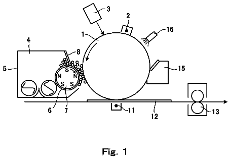
FIG. 1 is a configuration diagram schematically illustrating an example of an image forming apparatus according to an exemplary embodiment; and
FIG. 2 is a configuration diagram schematically illustrating an example of a process cartridge according to the exemplary embodiment.
Detailed description
Hereinafter, description will be given of an exemplary embodiment of the invention as an example.
Electrostatic Charge Image Developing Toner
An electrostatic charge image developing toner (hereinafter, referred to as a “toner”) according to the exemplary embodiment is a toner that includes toner particles that have an average circularity from 0.98 to 1.00 and a number-particle diameter distribution index (lower GSD) on a small diameter side of 1.22 or more and contain at least vinyl resin, and an external additive.
The external additive contains silica particles with a compression aggregation degree from 60% to 95% and a particle compression ratio from 0.20 to 0.40 (hereinafter, also referred to as “specific silica particles”).
Here, if an externally added structure of silica particles (a state where the silica particles adhere to toner particles) changes in a toner in the related art in which the silica particles are externally added to the toner particles, then fluidity of the toner may deteriorate, and a charge holding property may deteriorate. The silica particles move on the toner particles and are localized, or the silica particles flake from the toner particles, for example, and these are reasons of the change in the externally added structure. In a case of applying toner particles with average circularity that is as high as 0.98 to 1.00, which have almost spherical shapes, in particular, movement on the toner particles and flaking from the toner particle tend to occur, and the externally added structure tend to change.
If the toner particles with the average circularity that is as high as 0.98 to 1.00, which have almost spherical shapes, are applied, the toner particles tend to pass through the cleaning blade when the same image is repeatedly formed. If the toner particles have almost spherical shapes, the surfaces thereof are substantially smooth, and the toner particles are not easily scraped at the cleaning unit (the contact portion between the cleaning blade and the photoreceptor (image holding member)). Therefore, the toner particles tend to sip if the same image is repeatedly formed and a large number of toner particles reach the same region in the cleaning unit.
In contrast, the silica particles externally added to the toner particles flake from the toner particles due to a mechanical loads caused by stirring in a developing unit or scraping in the cleaning unit, for example, in some cases. If the flaking silica particles reach the cleaning unit, then the silica particles are stopped at a tip end of the cleaning unit (a site of a contact portion between the cleaning blade and the photoreceptor on a downstream side in a rotation direction) and forms an aggregate (hereinafter, also referred to as an “externally added dam”) by a pressure from the cleaning blade. The externally added dam contributes to an improvement in a cleaning property.
However, a large number of silica particles (silica particles at the externally added dam) stopped at the cleaning unit also pass when the toner particles pass, and the silica particles cause crack on the photoreceptor in some cases. Crack is caused on the photoreceptor when the silica particles pass through the cleaning blade. If crack is caused on the photoreceptor, defect in image quality such as streak occurs at the portion.
Thus, the toner according to the exemplary embodiment exhibits an excellent charge holding property and prevents crack on the photoreceptor caused when the same image is repeatedly formed by externally adding specific silica particles to the toner particles. If the toner according to the exemplary embodiment is applied to an image forming apparatus or the like, defect in image quality due to deterioration of the charge holding property of the toner (such as a change in image density over elapse of time) and defect in image quality due to crack on the photoreceptor caused when the same image is repeatedly formed are prevented. The reason is inferred as follows.
The specific silica particles with the compression aggregation degree and the particle compression ratio within the above ranges are silica particles that have characteristics such as high fluidity, high dispersibility in the toner particles, a high cohesion, and high adhesion to the toner particles.
Here, silica particles typically have low adhesion and a characteristic of not easily aggregating since the silica particles have low bulk density while the silica particles exhibit satisfactory fluidity.
In contrast, a technique of treating surfaces of the silica particles by using a hydrophobizing agent for the purpose of enhancing both fluidity of the silica particles and dispersibility in the toner particles is known. According to the technique, the fluidity of the silica particles and the dispersibility in the toner particles are enhanced while the cohesion is maintained to be low.
In addition, a technique of treating the surfaces of the silica particles by using both a hydrophobizing agent and silicone oil is also known. According to the technique, the adhesion to the toner particles and the cohesion are enhanced. On the other hand, the fluidity and the dispersibility in the toner particles tend to deteriorate.
That is, it is possible to state that the fluidity and the dispersibility in the toner particles are in a conflict relationship with the cohesion and the adhesion to the toner particles in the silica particles.
In contrast, the specific silica particles have four satisfactory properties, namely the fluidity, the dispersibility in the toner particles, the cohesion, and the adhesion to the toner particles, by setting the compression aggregation degree and the particle compression ratio within the above ranges as described above.
Next, description will be given of meaning that the compression aggregation degree and the particle compression ratio of the specific silica particles are set within the above ranges in order.
First, description will be given of meaning that the compression aggregation degree of the specific silica particles is set to the range from 60% to 95%.
The compression aggregation degree is an index indicating the cohesion of the silica particles and the adhesion to the toner particles. The index is indicated by how difficult a silica particle compact is disentangled in a case of dropping the silica particle compact after obtaining the compact by compressing a silica particle.
Therefore, the silica particles tend to have higher bulk density, higher cohesive force (intermolecular force), and higher adhesion to the toner particles as the compression aggregation degree increases. A method of calculating the compression aggregation degree will be described later in detail.
Therefore, the specific silica with a compression aggregation degree that is controlled to be as high as 60% to 95% has satisfactory adhesion to the toner particles and cohesion. However, the upper limit of the compression aggregation degree is set to 95% in terms of obtaining satisfactory adhesion to the toner particles and satisfactory cohesion while securing the fluidity and the dispersibility in the toner particles.
Next, description will be given of the meaning that the particle compression ratio of the specific silica particles is set to be from 0.20 to 0.40.
The particle compression ratio is an index indicating the fluidity of the silica particles. Specifically, the particle compression ratio is represented by a ratio ((hardened apparent specific gravity−loosened apparent specific gravity)/hardened apparent specific gravity) between a difference of the hardened apparent specific gravity and the loosened apparent specific gravity and the hardened apparent specific gravity of the silica particles.
Therefore, a lower particle compression ratio represents higher fluidity of the silica particles. In addition, there is a tendency that the dispersibility in the toner particles increases as fluidity increases. A method of calculating the particle compression ratio will be described later in detail.
Therefore, the specific silica particles with a particle compression ratio that is controlled to be as low as 0.20 to 0.40 have satisfactory fluidity and dispersibility in the toner particles. However, the lower limit of the particle compression ratio is set to 0.20 in terms of obtaining satisfactory adhesion to the toner particles and satisfactory cohesion while obtaining the satisfactory fluidity and the dispersibility in the toner particles.
As describe above, the specific silica particles have unique characteristics, namely the high fluidity, easiness of being dispersed in the toner particles, the high cohesive force, and the high adhesion force to the toner particles. Therefore, the specific silica particles with the compression aggregation degree and the particle compression ratio within the above ranges are silica particles that have characteristics, namely the high fluidity, the high dispersibility in the toner particles, the high cohesion, and the high adhesion to the toner particles.
Next, description will be given of an assumed effect achieved when the specific silica particles are externally added to the toner particles.
First, if the specific silica particles are externally added to the toner particles, then the specific silica particles tend to adhere to the surfaces of the toner particles in a substantially uniform state due to the high fluidity and the dispersibility in the toner particles. The specific silica particles which have once adhered to the toner particle do not easily move on the toner particles and flake from the toner particles by the mechanical loads caused by the stirring in the developing unit, for example, since the specific silica particles have high adhesion to the toner particles. That is, the externally added structure does not easily change. Therefore, the fluidity of the toner particles themselves is enhanced, and also, the high fluidity tends to be maintained. As a result, the deterioration of the charge holding property is prevented even if the toner particles with an easily changed externally added structure and almost spherical shapes are applied.
In contrast, the specific silica particles which have flaked from the toner particles due to the mechanical loads caused by the scraping at the cleaning unit and have been supplied to the tip end of the cleaning unit aggregate by a pressure from the cleaning blade due to a high cohesion and form an externally added dam with high strength. Therefore, the externally added dam further enhances the cleaning property, and the passing of the toner particles is prevented even if the same image is repeatedly formed and a large amount of toner particles with almost spherical shapes reach the same region of the cleaning unit. In the related art, an installation pressure of the cleaning blade on the photoreceptor is set to be high to perform scraping in order to clean the toner particles with almost spherical shapes. If the installation pressure is set to be high, the cleaning property is enhanced while the amount of the photoreceptor worn and the crack on the photoreceptor tend to increase. In contrast, the passing of a large amount of silica particles (silica particles at the externally added dam) and the crack on the photoreceptor due to the passing of the silica particles are prevented without raising the installation pressure of the cleaning blade by using the specific silica.
Next, description will be given of meaning of the toner particles.
The toner particles have a feature that the surface thereof is smooth to satisfy the above average circularity. Furthermore, the toner particles have also a feature that the number-particle diameter distribution index (lower GSD) on the small diameter side is 1.22 or more and the toner particles contain at least vinyl resin. The number-particle diameter distribution index (lower GSD) on the small diameter side indicates a rate of the amount of fine toner particles. Toner particles including a small amount of fine particles and having high average circularity tends to be closest-packed between the cleaning blade and the photoreceptor when the toner is scraped by the cleaning unit. The closest-packing tends to raise the pressure between the cleaning blade and the photoreceptor and cause crack on the photoreceptor. In contrast, an increase in the amount of fine particles tends to alleviate the closest-packing. Although the fine particles themselves have such particle diameters that make it difficult to perform the cleaning, a scraping property at the cleaning unit may be secured by using the specific silica particles. In addition, it is effective to use vinyl resin to prevent crack on the photoreceptor. Toner particles that do not contain vinyl resin (toner particles containing polyester resin, for example) are soft and easily collapsed at the cleaning blade portion. In contrast, use of vinyl resin enables hardening of the toner particles themselves, which effectively affects occurrence of crack on the photoreceptor due to the collapse of the toner containing the external additive at the cleaning blade.
The toner obtained by externally adding the specific silica particles to the toner particles with such features exhibits an effect that the external additive is dispersed in a substantially uniform state and the externally added structure may be maintained. The reason is inferred as follows. Since fumed silica particles, for example, have wide particle diameter distribution and cause a large amount of aggregation, the fumed silica particles are localized and it is difficult to externally add the fumed silica particles in a substantially uniform state even if the fumed silica particles are externally added to the toner particles in the related art. In a case of an external additive that has narrow particle diameter distribution and causes a small amount of aggregation, such as sol-gel silica particles, it is possible to disperse the external additive in a substantially uniform state immediately after the external addition. However, in a case where the toner particles have almost spherical shapes and the external additive also has an almost spherical shape, the external additive easily rolls over the toner particles and flaking tends to increase. In contrast, the specific silica particles may maintain the externally added structure even on the surfaces of smooth toner particles with almost spherical shapes while securing dispersibility of the sol-gel silica particles.
It is inferred that the toner according to the exemplary embodiment exhibits the excellent charge holding property and prevents crack on the photoreceptor when the same image is repeatedly formed for the above reasons.
In the toner according to the exemplary embodiment, the specific silica particles further preferably have a particle dispersion degree from 90% to 100%.
Here, description will be given of meaning that the particle dispersion degree of the specific silica particles is from 90% to 100%.
The particle dispersion degree is an index indicating dispersibility of the silica particles. The index is represented by how easily the silica particles in a primary particle state are dispersed in the toner particles. Specifically, the particle dispersion degree is represented by a ratio (actually measured coverage C/calculated coverage C.sub.0) between an actually measured coverage C on an attachment target and a calculated coverage C.sub.0, where C.sub.0 represents the calculated coverage of the silica particles on the surfaces of the toner particles and C represents the actually measured coverage.
Therefore, a higher particle dispersion degree represents that the silica particles do not easily aggregate and tend to be dispersed in the primary particle state in the toner particles. A method of calculating the particle dispersion degree will be described later in detail.
The specific silica particles exhibit further satisfactory dispersibility in the toner particles by controlling the compression aggregation degree and the particle compression ratio within the above ranges and controlling the particle dispersion degree to be as high as 90% to 100%. In doing so, the fluidity of the toner particles themselves are further enhanced, and also, the high fluidity tends to be maintained. As a result, the specific silica particles further tend to adhere to the surfaces of the toner particles in a substantially uniform state, and the deterioration of the charge holding property tends to be prevented.
Preferable examples of the specific silica particles that have the above characteristics, namely the high fluidity, the high dispersibility in the toner particles, the high cohesion, and the high adhesion to the toner particles in the toner according to the exemplary embodiment include silica particles with surfaces to which a siloxane compound with a relatively large weight average molecular weight adheres. Specifically, preferable examples thereof include silica particles having a siloxane compound having a viscosity of 1,000 cSt to 50,000 cSt attached on the surface thereof (preferably, the surface attachment amount of the siloxane compound is from 0.01% by weight to 5% by weight). The specific silica particles are obtained by a method of treating surfaces of silica particles with the siloxane compound having a viscosity of from 1,000 cSt to 50,000 cSt such that the surface attachment amount is from 0.01% by weight to 5% by weight.
Here, the surface attachment amount is a rate with respect to silica particles (untreated silica particles) before the surfaces of the silica particles are treated. Hereinafter, the silica particles before the surface treatment (that is, the untreated silica particles) will also be simply referred to as “silica particles”.
According to the specific silica particles obtained by treating the surfaces of silica particles by using the siloxane compound with viscosity from 1,000 cSt to 50,000 cSt such that the surface attachment amount is from 0.01% by weight to 5% by weight, the cohesion and the adhesion to the toner particles are enhanced as well as the fluidity and the dispersibility in the toner particles, and the compression aggregation degree and the particle compression ratio tend to satisfy the above requirements. In addition, the deterioration of the charge holding property and the crack on the photoreceptor tend to be prevented. This is considered to be caused by the following reasons though not clear.
If a small amount of siloxane compound with relatively high viscosity within the above range is made to adhere to surfaces of silica particles at an amount within the above range, then a function derived from properties of the siloxane compound on the surfaces of the silica particles appears. Although the mechanism is not clear, a release property derived from the siloxane compound tends to occur by the small amount of siloxane compound with the relatively high viscosity adhering to the silica particles within the above range, or adhesion between the silica particles is reduced by a decrease in force between the particles due to steric hindrance of the siloxane compound when the silica particles flow. Therefore, the fluidity of the silica particles and the dispersibility in the toner particles are further enhanced.
In contrast, when the silica particles are pressurized, long molecular chains of the siloxane compound on the surfaces of the silica particles get entangled, a closest packed property of the silica particles is enhanced, and aggregation between the silica particles is strengthened. The cohesive force of the silica particles caused by the long molecular chains of the siloxane compound being entangled is considered to be released if the silica particles are made to flow. In addition, the long molecular chains of the siloxane compound on the surfaces of the silica particles enhance adhesion force to the toner particles.
As described above, according to the specific silica particles obtained by causing the small amount of siloxane compound with the viscosity within the above range to adhere to the surfaces of the silica particles at an amount within the above range, the compression aggregation degree and the particle compression ratio tend to satisfy the above requirements, and the particle dispersion degree tends to satisfy the above requirement.
Hereinafter, detailed description will be given of a configuration of the toner.
Toner Particles
The toner particles contain a binder resin, for example. The toner particles may contain a coloring agent, a release agent, other additives, and the like as needed.
Binder Resin
Vinyl resin is applied as the binder resin. Examples of the vinyl resin include a vinyl resin such as homopolymer of a polymerizable monomer or a copolymer of two or more kinds of polymerizable monomers such as styrene polymerizable monomer (such as styrene, parachlorostyrene, or α-methylstyrene), (meth)acryl polymerizable monomer (such as (meth)acrylic acid, methyl acrylate, ethyl acrylate, n-propyl acrylate, n-butyl acrylate, lauryl acrylate, 2-ethylhexyl acrylate, methyl methacrylate, ethyl methacrylate, n-propyl methacrylate, lauryl methacrylate, or 2-ethylhexyl methacrylate), ethylenically unsaturated nitrile polymerizable monomer (such as acrylonitrile, or methacrylonitrile), vinyl ether polymerizable monomer (such as vinyl methyl ether, or vinyl isobutyl ether), vinyl ketone polymerizable monomer (vinyl methyl ketone, vinyl ethyl ketone, or vinyl isopropenyl ketone), or olefin polymerizable monomer (such as ethylene, propylene, or butadiene).
As the binder resin other than vinyl resin, non-vinyl resin such as epoxy resin, polyester resin, polyurethane resin, polyamide resin, cellulose resin, polyether resin, or modified rosin, a mixture of such non-vinyl resin and the vinyl resin, and graft polymer obtained by polymerizing vinyl monomer in presence of the non-vinyl resin may be used together. However, the amount of vinyl resin is preferably equal to or greater than 50% by weight (more preferably 80% by weight, further preferably equal to or greater than 90% by weight) with respect to the entire binder resin.
One kind or two or more kinds of such binder resin may be used alone or in combination.
Preferable examples of vinyl resin from among these examples include styrene (meth)acrylic resin.
The styrene (meth)acrylic resin is copolymer obtained by copolymerizing at least styrene polymerizable monomer (polymerizable monomer having a styrene skeleton) with (meth)acryl polymerizable monomer (polymerizable monomer having a (meth)acryloyl skeleton).
“(Meth)acryl” is an expression including both “acryl” and “methacryl”.
Examples of the styrene polymerizable monomer include styrene, alkyl-substituted styrene (such as α-methylstyrene, 2-methylstyrene, 3-methylstyrene, 4-methylstyrene, 2-ethylstyrene, 3-ethylstyrene, or 4-ethylstyrene), halogen-substituted styrene (such as 2-chlorostyrene, 3-chlorostyrene, or 4-chlorostyrene), and vinylnaphthalene. One kind or two kinds or more of styrene polymerizable monomer may be used alone or in combination.
From among these examples, styrene is preferably used as the styrene monomer in terms of reactivity, easiness of reaction control, and availability.
Examples of (meth)acryl polymerizable monomer include (meth)acrylic acid and (meth)acrylic acid ester. Examples of (meth)acrylic acid ester include (meth)acrylic acid alkyl ester (such as methyl (meth)acrylate, ethyl (meth)acrylate, n-propyl (meth)acrylate, n-butyl (meth)acrylate, n-pentyl (meth)acrylate, n-hexyl acrylate, n-heptyl (meth)acrylate, n-octyl (meth)acrylate, n-decyl (meth)acrylate, n-dodecyl (meth)acrylate, n-lauryl (meth)acrylate, n-tetradecyl (meth)acrylate, n-hexadecyl (meth)acrylate, n-octadecyl (meth)acrylate, isopropyl (meth)acrylate, isobutyl (meth)acrylate, t-butyl (meth)acrylate, isopentyl (meth)acrylate, amyl (meth)acrylate, neopentyl (meth)acrylate, isohexyl (meth)acrylate, isoheptyl (meth)acrylate, isooctyl (meth)acrylate, 2-ethylhexyl (meth)acrylate, cyclohexyl (meth)acrylate, or t-butylcyclohexyl (meth)acrylate), (meth)acrylic acid aryl ester (such as phenyl (meth)acrylate, biphenyl (meth)acrylate, diphenylethyl (meth)acrylate, t-butylphenyl (meth)acrylate, or terphenyl (meth)acrylate), dimethylaminoethyl (meth)acrylate, diethylaminoethyl (meth)acrylate, methoxyethyl (meth)acrylate, 2-hydroxyethyl (meth)acrylate, β-carboxyethyl (meth)acrylate, and (meth)acrylamide. One kind or two or more kinds of (meth)acrylic acid polymerizable monomer may be used alone or in combination.
A copolymerization ratio (based on weight; styrene polymerizable monomer/(meth)acryl polymerizable monomer) between the styrene polymerizable monomer and the (meth)acryl polymerizable monomer is preferably from 85/15 to 70/30, for example.
The styrene (meth)acrylic resin may have a crosslinked structure. Examples of the styrene (meth)acrylic resin having a crosslinked structure include a crosslinked product obtained by copolymerizing at least styrene polymerizable monomer, (meth)acrylic acid polymerizable monomer, and crosslinkable monomer, for example.
Examples of the crosslinkable monomer include a difunctional crosslinking agent.
Examples of the difunctional crosslinking agent include divinylbenzene, divinylnaphthalene, a di(meth)acrylate compound (such as diethylene glycol di(meth)acrylate, methylene bis(meth)acrylamide, decanediol diacrylate, or glycidyl (meth)acrylate), polyester-type di(meth)acrylate, and 2-([1′-methylpropylideneamino] carboxyamino) ethyl methacrylate.
Examples of polyfunctional crosslinking agent include a tri(meth)acrylate compound (such as pentaerythritol tri(meth)acrylate, trimethylolethane tri(meth)acrylate, or trimethylolpropane tri(meth)acrylate), a tetra(meth)acrylate compound (such as tetramethylolmethane tetra(meth)acrylate, or oligoester (meth)acrylate), 2,2-bis(4-methacryloxy, polyethoxyphenyl) propane, diallylphthalate, triallyl cyanurate, triallyl isocyanurate, triallyl trimellitate, and diaryl chlorendate.
A copolymerization ratio (based on weight; crosslinkable monomer/entire monomer) of the crosslinkable monomer with respect to the entire monomer is preferably from 2/1,000 to 30/1,000.
The glass transition temperature (Tg) of the styrene (meth)acrylic resin is preferably from 50° C. to 75° C., more preferably from 55° C. to 65° C., and further preferably from 57° C. to 60° C., for example, in terms of the fixing property.
The glass transition temperature is determined by a DSC curve obtained by a differential scanning calorimetry (DSC). More specifically, the glass transition temperature is determined based on “Extrapolation glass transition onset temperature” described in how to determine glass transition temperature in JIS K 7121-1987 “Testing methods for transition temperatures of plastics”.
The weight average molecular weight of styrene (meth)acrylic resin is preferably from 30,000 to 200,000, more preferably from 40,000 to 100,000, and further preferably from 50,000 to 80,000, for example, in terms of storage stability.
The weight average molecular weight is measured by gel permeation chromatography (GPC). The molecular weight measurement by the GPC is performed by using GPC.HLC-8120GPC manufactured by Tosoh Corporation as a measurement apparatus, a column TSKgel SuperHM-M (15 cm) manufactured by Tosoh Corporation, and a THF solvent. The weight average molecular weight is calculated by using a molecular weight calibration curve created by a mono-dispersed polystyrene standard sample from the measurement result.
The content of the binder resin is preferably from 40% by weight to 95% by weight, more preferably from 50% by weight to 90% by weight, and further preferably from 60% by weight to 85% by weight with respect to the entire toner particles, for example.
Coloring Agent
Examples of coloring agent include various pigments such as carbon black, chrome yellow, hansa yellow, benzidine yellow, threne yellow, quinoline yellow, pigment yellow, permanent orange GTR, pyrazolone orange, vulcan orange, watchung red, permanent red, brilliant carmine 3B, brilliant carmine 6B, du pont oil red, pyrazolone red, lithol red, rhodamine B lake, lake red C, pigment red, rose Bengal, aniline blue, ultramarine blue, calco oil blue, methylene blue chloride, phthalocyanine blue, pigment blue, phthalocyanine green, and malachite green oxalate or various dyes such as an acridine dye, a xanthene dye, an azo dye, a benzoquinone dye, an azine dye, an anthraquinone dye, a thioindigo dye, a dioxazine dye, a thiazine dye, an azomethine dye, an indigo dye, a phthalocyanine dye, an aniline black dye, a polymethine dye, a triphenylmethane dye, a diphenylmethane dye, and a thiazol dye.
One kind or two or more kinds of the coloring agents may be used alone or in combination.
As the coloring agent, a surface-treated coloring agent may be used as needed, or a coloring agent may be used along with a dispersant. Multiple coloring agents may be used together.
The content of the coloring agent is preferably from 1% by weight to 30% by weight, and more preferably from 3% by weight to 15% by weight with respect to the entire toner particles, for example.
Release Agent
Examples of the release agent include hydrocarbon wax; natural wax such as carnauba wax, rice wax, or candelilla wax; synthesized or mineral.petroleum wax such as montan wax; and ester wax such as fatty acid ester or montanic acid ester. The release agent is not limited thereto.
The melting temperature of the release agent is preferably from 50° C. to 110° C., and more preferably from 60° C. to 100° C.
The melting temperature is obtained based on “Melting peak temperature” described in how to obtain a melting temperature in JIS K 7121-1987 “Testing methods for transition temperatures of plastics” from a DSC curve obtained by a differential scanning calorimetry (DSC).
The content of the release agent is preferably from 1% by weight to 20% by weight, and more preferably from 5% by weight to 15% by weight with respect to the entire toner particles, for example.
Other Additives
Examples of other additives include known additives such as a magnetic material, a charge-controlling agent, and inorganic powder. Such additives are contained in the toner particles as internal additives.
Properties of Toner Particles
The toner particles may be toner particles with a single layer structure or may be toner particles with a so-called core-shell structure formed of a core (core particle) and a covering layer (shell layer) covering the core.
Here, the toner particles with the core-shell structure is preferably formed of a core including a binder resin, and if necessary, other additives such as a coloring agent and a release agent and a covering layer including a binder resin, for example.
The volume average particle diameter (D50v) of the toner particles is preferably from 2 μm to 10 μm, and more preferably from 4 μm to 8 μm.
As for the number-particle diameter distribution index (lower GSD) on the small diameter side of the toner particles, the toner particles have particle diameter distribution of 1.22 or more. The number-particle diameter distribution index (lower GSD) in the particle diameter distribution of the toner particles is preferably equal to or less than 1.5 and more preferably equal or less than 1.4 in terms of a rate of the amount of fine particles at which the effects of the specific silica may be exhibited. If the number-particle diameter distribution index is greater than the range, defect in image quality such as fogging occurs during the development in some cases.
The volume average particle diameter and particle diameter distribution index of the toner particles are measured by using a COULTER MULTISIZER II (manufactured by Beckman Coulter, Inc.) and ISOTON-II (manufactured by Beckman Coulter, Inc.) as an electrolyte.
For the measurement, 0.5 mg to 50 mg of a measurement sample is added to 2 ml of 5% aqueous solution of a surfactant (preferably sodium alkylbenzene sulfonate) as a dispersant. This mixture is added to 100 ml to 150 ml of electrolyte.
The electrolyte in which the sample is suspended is subjected to dispersion processing by an ultrasonic disperser for 1 minute, and particle diameter distribution of the particles with particle diameters within a range from 2 μm to 60 μm is measured by using an aperture with an aperture diameter of 100 μm by a COULTER MULTISIZER II. The number of particles to be sampled is 50,000.
Cumulative distribution of the volume and the number are depicted from the smaller diameter side, respectively, in the particle diameter range (channel) divide based on the particle diameter distribution to be measured, the particle diameter corresponding to accumulation of 16% is defined to have a volume particle diameter D16v and a number particle diameter D16p, a particle diameter corresponding to accumulation of 50% is defined to have a volume average particle diameter D50v and a cumulative number average particle diameter D50p, and a particle diameter corresponding to accumulation of 84% is defined to have a volume particle diameter D84v and a number particle diameter D84p.
The volume-particle diameter distribution index (GSDv) is calculated as (D84v/D16v).sup.1/2, and the number-particle diameter distribution index (GSDp) is calculated as (D84p/D16p).sup.1/2 by using the values. The number-particle diameter distribution index (lower GSD) on the small diameter side is calculated as (D50p/D16p).sup.1/2.
The average circularity of the toner particles is from 0.98 to 1.00, and preferably from 0.99 to 1.0. That is, the toner particles preferably have almost spherical shapes.
The average circularity of the toner particles is measured by FPIA-3000 manufactured by Sysmex Corporation. The apparatus employs a scheme of measuring particles dispersed in water, for example, by a flow image analysis method, and the suctioned particle suspension is introduced into a flat sheath flow cell, and a flat sample flow is formed by a sheath solution. The passing particles are captured as a stationary image by a CCD camera through an objective lens by irradiating the sample flow with strobe light. The captured particle image is subjected to two-dimensional image processing, and the circularity is calculated from a projection area and a perimeter. As for the circularity, average circularity is obtained by respectively analyzing at least 4,000 images and performing statistical processing. Equation: circularity=equivalent circle diameter perimeter/perimeter=[2×( A π).sup.1/2]/PM
In the above equation, A represents a projection area, and PM represents a perimeter.
For the measurement, an HPF mode (high resolution mode) is used, and dilution magnification is set to 1.0 fold. For data analysis, a circularity analysis range is set to a range from 0.40 to 1.00 for the purpose of removing measurement noise.
External Additive
External additives include the specific silica particles. The external additives may include external additives other than the specific silica particles. That is, only the specific silica particles may be externally added, or the specific silica particles and other external additives may be externally added to the toner particles.
Specific Silica Particles
Compression Aggregation Degree
Although the compression aggregation degree of the specific silica particles is from 60% to 95%, the compression aggregation degree is preferably from 80% to 95%, and more preferably from 85% to 93% in terms of obtaining satisfactory cohesion of the specific silica particles and satisfactory adhesion to the toner particles and also securing the fluidity and the dispersibility in the toner particles (particularly, in terms of the charge holding property and preventing crack on the photoreceptor).
The compression aggregation degree is calculated by the following method.
A disk-shaped mold with a diameter of 6 cm is filled with 6.0 g of specific silica particles. Then, the mold is compressed with a pressure of 5.0 t/cm2 for 60 seconds by using a compression molding machine (manufactured by Maekawa Testing Machine Co., Ltd.), and the compressed disk-shaped compact of the specific silica particles (hereinafter, referred to a “compact before falling”) is obtained. Thereafter, the weight of the compact before falling is measured.
Then, the compact before falling is arranged on a screening mesh with an aperture of 600 μm, and the compact before falling is made to fall by a vibration classifier (manufactured by Tsutsui Scientific Instruments Co., Ltd., model number: VIBRATING MVB-1) under conditions of an amplitude of 1 mm and a vibration time of 1 minute. In doing so, the specific silica particles fall from the compact before falling through the screening mesh, and the compact of the specific silica particles remains on the screening mesh. Thereafter, the weight of the compact of the remaining specific silica particles (hereinafter, referred to as a “compact after falling”) is measured.
The description continues in the full USPTO document.
 Lapsed, fee not paid4 drawings