 Lapsed, fee not paid5 drawings
Biotech & Lab · US 9,784,672 B2
Foodstuff analysis device
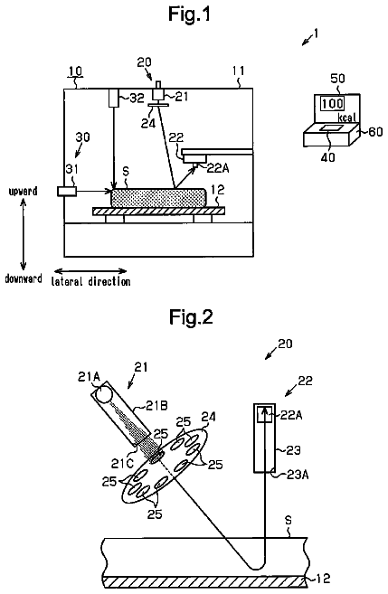
Provided is a foodstuff analysis device capable of readily calculating calories or component weights.
US 9,784,734 B2 · Assignee: CHEMBIO DIAGNOSTIC SYSTEMS, INC. · Inventors: Esfandiari; Javanbakhsh
Sheet 1 of 8 from the published document. All sheets in the USPTO PDF
Systems include test cells with sorbent material in a T-shape and defining a first flow path for a solution and a second flow path for a sample, and a test line or test site with immobilized antigens or antibodies or other ligand binding molecules located at the junction of the T. A housing houses the sorbent material and defines a first hole adjacent an end of the first flow path for receiving the solution and a second hole adjacent an end of the second flow path for receiving the sample.
1 of 8 drawing sheets so far from the published document, cropped to the drawing. Every sheet is in the USPTO PDF.
What the patent claimed, word for word. All of it is now free to use.
This invention relates broadly to immunoassay devices and the methods for their use. More particularly, this invention relates to chromatographic rapid test strips for detection of a ligand in a body fluid.
2. State of the Art
Many types of ligand-receptor assays have been used to detect the presence of various substances, often generally called ligands, in body fluids such as blood, urine, or saliva. These assays involve antigen antibody reactions, synthetic conjugates comprising radioactive, enzymatic, fluorescent, or visually observable polystyrene or metal sol tags, and specially designed reactor chambers. In all these assays, there is a receptor, e.g., an antibody, which is specific for the selected ligand or antigen, and a means for detecting the presence, and in some cases the amount, of the ligand-receptor reaction product. Some tests are designed to make a quantitative determination, but in many circumstances all that is required is a positive/negative qualitative indication. Examples of such qualitative assays include blood typing, most types of urinalysis, pregnancy tests, and AIDS tests. For these tests, a visually observable indicator such as the presence of agglutination or a color change is preferred.
Even the qualitative assays must be very sensitive because of the often small concentration of the ligand of interest in the test fluid. False positives can also be troublesome, particularly with agglutination and other rapid detection methods such as dipstick and color change tests. Because of these problems, so-called “sandwich” assays and other sensitive detection mechanisms which use metal sols or other types of colored particles have been developed.
In a “sandwich” assay, a target analyte such as an antigen is “sandwiched” between a labeled antibody and an antibody immobilized onto a solid support. The assay is read by observing the presence and/or amount of bound antigen-labeled antibody complex. In a “competition” immunoassay, antibody bound to a solid surface is contacted with a sample containing an unknown quantity of antigen analyte and with labeled antigen of the same type. The amount of labeled antigen bound on the solid surface is then determined to provide an indirect measure of the amount of antigen analyte in the sample.
Because these and other assays can detect both antibodies and antigens, they are generally referred to as immunochemical ligand-receptor assays or simply immunoassays.
Solid phase immunoassay devices, whether of the sandwich or competition type, provide sensitive detection of an analyte in a biological fluid sample such as blood, urine, or saliva. Solid phase immunoassay devices incorporate a solid support to which one member of a ligand-receptor pair, usually an antibody, antigen, or hapten, is bound. Common early forms of solid supports were plates, tubes, or beads of polystyrene which were well known from the fields of radioimmunoassay and enzyme immunoassay. In the last decade, a number of porous materials such as nylon, nitrocellulose, cellulose acetate, glass fibers, and other porous polymers have been employed as solid supports.
A number of self-contained immunoassay kits using porous materials as solid phase carriers of immunochemical components such as antigens, haptens, or antibodies have been described. These kits are usually dipstick, flow-through, or migratory in design.
In the more common forms of dipstick assays, as typified by home pregnancy and ovulation detection kits, immunochemical components such as antibodies are bound to a solid phase. The assay device is “dipped” for incubation into a sample suspected of containing unknown antigen analyte. Enzyme-labeled antibody is then added, either simultaneously or after an incubation period. The device is then washed and inserted into a second solution containing a substrate for the enzyme. The enzyme-label, if present, interacts with the substrate, causing the formation of colored products which either deposit as a precipitate onto the solid phase or produce a visible color change in the substrate solution.
Flow-through type immunoassay devices were designed to obviate the need for extensive incubation and cumbersome washing steps associated with dipstick assays. Valkirs et al., U.S. Pat. No. 4,632,901, disclose a device comprising antibody (specific to a target antigen analyte) bound to a porous membrane or filter to which is added a liquid sample. As the liquid flows through the membrane, target analyte binds to the antibody. The addition of sample is followed by addition of labeled antibody. The visual detection of labeled antibody provides an indication of the presence of target antigen analyte in the sample.
Korom et al., EP-A 0 299 359, discloses a variation in the flow-through device in which the labeled antibody is incorporated into a membrane which acts as a reagent delivery system.
The requirement of multiple addition and washing steps with dipstick and flow-through type immunoassay devices increases the likelihood that minimally trained personnel and home users will obtain erroneous assay results.
In migration type assays, a membrane is impregnated with the reagents needed to perform the assay. An analyte detection zone is provided in which labeled analyte is bound and assay indicia is read. See, for example, Tom et al., U.S. Pat. No. 4,366,241, and Zuk, et al. U.S. Pat. No. 4,956,275. The sensitivity of migration type assays is frequently reduced, however, by the presence or formation in the sample of undesirable solid components which block the passage of labeled analyte to the detection zone. Assay sensitivity also declines when migration assay devices are flooded with too much liquid sample.
Migration assay devices usually incorporate within them reagents which have been attached to colored labels (i.e., conjugates), thereby permitting visible detection of the assay results without addition of further substances. See, for example, Bernstein, U.S. Pat. No. 4,770,853. Among such labels are gold sol particles such as those described by Leuvering in U.S. Pat. No. 4,313,734, dye sol particles such as described in U.S. Pat. No. 4,373,932 by Gribnau et al., dyed latex such as described by May et al., WO 88/08534, and dyes encapsulated in liposomes by Campbell et al., U.S. Pat. No. 4,703,017. These colored labels are generally limited in terms of the immobilization methods which are suitable. Moreover, they require a relatively large amount of ligand molecule and can involve expensive reagents, thereby adding to the cost. Thus, there still remains a need for extremely reliable but inexpensive rapid detection devices. There also still remains a need for a highly sensitive assay which can utilize a small sample volume while providing accurate results.
It is therefore an object of the invention to provide a rapid detection immunoassay device.
It is another object of the invention to provide immunoassay devices which are simple to use and provide accurate results.
It is a further object of the invention to provide immunoassay devices which do not require migration of analytes along the same path as conjugate carrying buffer solutions.
It is also an object of the invention to provide rapid detection immunoassay devices which are simple in construction.
It is an additional object of the invention to provide immunoassay devices which can use either a dry or liquid conjugate system.
Another object of the invention is to provide a highly sensitive immunoassay device which provides accurate results while using small sample volumes.
A further object of the invention is to provide highly sensitive immunoassay devices which are useful with different types of body fluids.
In accord with these objects, which will be discussed in detail below, both dry and liquid conjugate immunoassay device systems are provided. The systems of the invention include test cells with a first sorbent material having a first location for receiving a buffer solution (in the case of a dry conjugate system) or a conjugate solution (in the case of a liquid conjugate system) with the first sorbent material defining a first horizontal flow path, a second sorbent material having a second location for receiving a sample with the second sorbent material defining a second horizontal flow path distinct from the first flow path, and a test line or test site with immobilized antigens or antibodies or other ligand binding molecules such as aptamers, nucleic acids, etc. located in a test zone at a junction of the first and second sorbent materials. For purposes herein, the term “distinct” when used in conjunction with the words “flow path” or “migration path” shall be understood to mean “not in fluid communication except via a test zone”.
Where the test cell of the invention is provided in a housing, the housing is provided with a first opening adjacent the first location and a second opening adjacent the second location. A viewing window is provided in the housing above the test line.
In the preferred embodiment of the invention, the first sorbent material and second sorbent material are separate pieces which overlie one another and the test line is printed on one or both of the sorbent materials at the junction. Alternatively, although not preferred, the first and second sorbent materials can be integral with each other. The systems of the invention preferably also include a control line or site which may be seen from the viewing window.
According to one set of embodiments of the invention, the sorbent materials of the invention (and the housing in which the materials are provided) are laid out in a T shape, where the first location for receiving the buffer or buffer-conjugate solution is located near one end of the top bar of the T, the second location for receiving the sample is located near the end of the stem of the T, and the sorbent materials overlie each other at the intersection. According to another set of embodiments of the invention, the sorbent materials of the invention (and the housing in which the materials are provided) take a + shape, where the first location for receiving the buffer or buffer-conjugate solution is located near one end of a first bar, the second location for receiving the sample is located near the end of one end of the second bar, and the sorbent materials overlie each other at the intersection. Of course, the sorbent materials may be laid out in other configurations, and the housing may take other shapes, such as rectangular, square, irregular, etc. regardless of the manner in which the sorbent materials are arranged.
In one embodiment of the invention, the materials, thicknesses and lengths of the first and second sorbent materials are chosen to adjust the timing regarding the liquid sample and liquid buffer reaching the test site.
In the dry conjugate system of the invention, a dry conjugate is provided between the first opening and the test site. The conjugate is supported on or within the sorbent material such that when a buffer is added in the first opening, the sorbent material wicks the buffer to the conjugate which is then carried by the buffer to the test site. In the liquid conjugate system of the invention, a buffer-conjugate liquid subsystem is provided and applied to the first opening. The sorbent material then wicks the buffer-conjugate subsystem to the test site.
According to one method of the invention, a system is provided which includes a test cell having a first sorbent material having a first location for receiving a buffer solution (in the case of a dry conjugate system) or a conjugate solution (in the case of a liquid conjugate system) with the first sorbent material defining a first horizontal flow path, a second sorbent material having a second location for receiving a sample with the second sorbent material defining a second horizontal flow path distinct from the first flow path, and a test line or test site with immobilized antigens or antibodies or other ligand binding molecules such as aptamers, nucleic acids, etc. located in a test zone at a junction of the first and second sorbent materials. If desired, a housing is also provided having a first opening for receiving the buffer or conjugate solution, a second opening for receiving a sample, and a viewing window above the test line. A sample of interest is provided to the second opening or location. After a desired amount of time, a liquid such as a buffer solution is added to the first opening or location. If the sorbent material is supporting a conjugate (i.e., in a dry conjugate system), the liquid is preferably simply a buffer solution. If the sorbent material is not supporting a conjugate (i.e., in a liquid conjugate system), the liquid is preferably a buffer-conjugate liquid subsystem. In any event, after sufficient time to permit the conjugate to migrate to the test site (and control site if provided), the test site (and control site if provided) is inspected in order to determine whether the sample is “positive” or not.
It will be appreciated that the system of the invention can be used in conjunction with different types of samples such as blood, urine, saliva, and feces, and can be used to test for the presence of any ligand. Where blood, saliva or feces is to be provided, the blood, saliva or feces may be diluted or mixed with buffer prior to being added through the second hole. Alternatively, in some cases, the sample may be added through the hole and then a diluent may be added through the same hole.
The test cell of the invention is advantageous over the prior art because the test cell of the invention overcomes aggregation/agglutination problems between the conjugate and the analyte in the sample which is a significant problem in traditional chromatographic immunoassay for relatively large analytes such as bacteria. In particular, in traditional chromatographic immunoassays, the complex between bacteria and conjugated antibody has difficulty migrating to the test line and tends to remain in the bottom of test strip or in the pad. In this invention there is no complex binding between analyte and the conjugate until the sample reaches the test site, as the analyte is applied via its own path to the test site while the conjugate migrates by itself. As a result, the system of the invention is extremely sensitive and specific.
Additional objects and advantages of the invention will become apparent to those skilled in the art upon reference to the detailed description taken in conjunction with the provided figures.
FIG. 1 is a top schematic view of a first embodiment of the invention.
FIG. 1A is a cross-sectional view taken along line 1 A- 1 A of FIG. 1 .
FIG. 1B is a cross-sectional view taken along line 1 B- 1 B of FIG. 1 .
FIG. 2 is a top schematic view of a second embodiment of the invention.
FIG. 2A is a cross-sectional view taken along line 2 A- 2 A of FIG. 2 .
FIG. 3 is a cross-sectional view of a third embodiment of the invention.
FIG. 4 is a top schematic view of a fourth embodiment of the invention.
FIG. 5 is a top schematic view of a fifth embodiment of the invention.
FIG. 6 is a top schematic view of a sixth embodiment of the invention.
FIG. 7 is a top schematic view of a seventh embodiment of the invention.
FIG. 8 is a top schematic view of an eighth embodiment of the invention.
FIG. 9 is a top schematic view of a ninth embodiment of the invention.
FIG. 10 is a top schematic view of an implementation of the invention which does not use a housing.
FIG. 11 is a table showing a comparison of the sensitivity of the test device of the invention relative to a typical prior art TB test device.
FIG. 12 includes two tables and a key, with the tables showing comparisons of the sensitivity of the test device of the invention relative to typical prior art HIV1 and HIV2 test devices.
Turning now to FIGS. 1, 1A and 1B , an immunoassay device test cell 10 is provided and includes: a T-shaped housing 20 having a top wall 21 defining first and second holes 24 , 26 , and a window 28 ; and first and second sorbent or bibulous materials 30 , 32 defining perpendicular horizontal flow paths in the housing. The first sorbent material 30 includes at least two and preferably three or four zones and may be made from a plurality of materials. A first zone 31 (sometimes called a filter zone) is located at the first hole 24 and extends to a second zone 33 (sometimes called a test zone) which is located at the junction of the “T”. The first zone 31 preferably includes a filter 31 a , a pad 31 b on or in which a conjugate 39 having desired antigens or antibodies with attached colored markers is deposited and immobilized, and a first portion of a thin membrane or sorbent or bibulous material 30 typically made from nitrocellulose with a plastic backing (not shown). The first zone 31 is adapted to receive a buffer solution, to cause the buffer solution to contact the conjugate, thereby mobilizing the conjugate, and to wick the conjugate-carrying buffer solution to the second zone 33 . The second (test) zone 33 includes a second portion of the thin membrane 30 which is preferably printed with a test line 50 having immobilized antigens or antibodies (depending on whether the test cell is designed to test for the presence of antibodies or antigens) on the membrane as is well known in the art. The test line 50 may be seen through the window 28 of clear plastic provided in the housing. An optional third zone 35 (sometimes called a control zone) which includes a third portion of the thin membrane 30 may also be printed with a control line 60 typically containing antibodies to the conjugate antigens (or in some cases antibodies which will bind to conjugate antibodies, or even antigens which will bind to conjugate antibodies) as is well known in the art. Where the third zone 35 is provided, window 28 extends above the control line 60 . If desired, an optional fourth zone 37 (sometimes called a reservoir zone) may be provided as a wicking reservoir as is also well known in the art. The fourth zone 37 includes a relatively thicker absorbent paper 31 d . Preferably overlying all the zones is a thin, preferably transparent plastic film or card 38 a having an adhesive which keeps the sorbent materials in place. The card 38 a may be cut with an opening at hole 24 so that it does not block liquid access to the hole 24 .
The second sorbent material 32 may also be made from a plurality of materials and preferably includes two zones 61 , 63 . The first zone 61 (sometimes called a filter zone) includes a filter or pad 62 and a first portion of a thin membrane or sorbent or bibulous material 32 typically made from nitrocellulose with a backing (not shown). The first zone 61 is located at the second hole 26 and extends to the second zone 63 . The second zone 63 includes a second portion of the thin membrane 32 which is in contact with the second zone 33 of the first sorbent material 30 . As is seen in FIGS. 1A and 1B , the first sorbent material 30 overlies the second sorbent material 32 such that the membranes are in contact with each other (as opposed to the backings contacting the membranes or each other), and such that the test line 50 is effectively located between the membranes. Thus, test line 50 could be printed on the second zone 63 of the second sorbent material 32 instead of, or in addition to the second zone 33 of the first sorbent material 30 . If desired, a thin plastic film or card 38 b having an adhesive which keeps the second sorbent material in place may be utilized.
Where standard-type nitrocellulose strips with a backing are utilized as the first and second membranes, it is desirable for the membranes to have different pore sizes. For example, and as discussed in more detail hereinafter, if membrane 31 (for the conjugate migration) has a 3μ pore size, and membrane 32 (for the sample migration) has a 15μ pore size, sample applied to membrane 32 will tend to migrate and stay in the sample membrane 32 and will tend not to migrate into the conjugate membrane 31 .
The immunoassay of FIG. 1 is preferably utilized as follows. First, a sample (not shown) possibly containing antibodies (or antigens) is provided to the second opening or hole 26 and allowed to migrate through the second sorbent material 32 to its second zone 63 which is contact with the second zone 33 of the first sorbent material 30 . Optionally, after providing the sample to hole 26 , a preferably measured amount of liquid such as a buffer solution may be added to hole 26 to help in the migration of the sample. Regardless, the sample reaches the test line 50 which is printed atop the second zone 33 of the first sorbent material or infused therein. After a desired amount of time, by which time the antibodies (or antigens) in the sample (if present) will have had an opportunity to bind to the antigens (or antibodies) immobilized at the test line 50 , a preferably measured amount of liquid such as a buffer solution (not shown) is added to the first opening 24 . After another period of time, sufficient to permit the conjugate to migrate to the test site 50 (and control site 60 if provided), the test site 50 (and control site 60 if provided) is inspected via window 28 in order to determine whether the sample is “positive” or not. Typically, a “positive” test indicating the presence of the antibody (or antigen) in the sample is obtained when both the test site 50 and the control site 60 show lines of color. A “negative” test indicating the lack of the presence of the antibody (or antigen) in the sample is obtained when only the control site 60 shows a line of color.
The method of the invention may be expedited by providing the housing with numbering and/or lettering to indicate that hole 26 is for receiving the sample (and optionally some buffer) and is to be used first, and that hole 24 is for receiving the buffer solution and is to be used second.
Those skilled in the art will appreciate that the immunoassay 10 functions as follows. Because the test line 50 is provided with antigens (or antibodies) immobilized on a membrane, if the test sample contains antibodies to the antigens (or antigens to the antibodies), the antibodies (or antigens) will bind themselves to the antigens (or antibodies) at the test line. Thereafter, when the conjugate 39 containing an antigen for the antibody (or antibody for the antigen) coupled to a colored marker is caused to migrate to the test line, if the test sample contains the antibodies (or antigens) which are now held at the test line 50 , the antigen (or antibody) of the conjugate will bind itself to the antibodies (or antigens) and the colored marker will cause a colored line to appear at the test site 50 . If the test sample does not contain antibodies (or antigens), the conjugate will not have the antibodies (antigens) to bind to at the test line 50 , and no colored line will appear at the test site 50 . On the other hand, because the control line 60 is provided with antibodies (or antigens), the antigens (or antibodies) of the conjugate will always bind to the antibodies (or antigens) in the control line 60 , thereby causing a colored line to appear at the control site 60 if the conjugate reaches the control site 60 . Thus, if sufficient buffer solution is provided to the test cell, a colored line should always appear at the control site 60 , thereby providing a control for the test.
Turning now to FIG. 2 and FIG. 2A , a second embodiment of the invention is seen. In FIGS. 1, 1A, 1B, 2 and 2A , like numbers are used for like elements. Thus, it will be appreciated that the primary difference between the second embodiment of FIGS. 2 and 2A and the first embodiment of FIGS. 1, 1A, and 1B is that the second sorbent material 32 a of test cell 10 a is key-shaped (preferably via punching). With the key-shaped arrangement, zone 61 a is shaped so that it converges to the second narrow zone 63 a . As a result, zone 63 a touches the second zone 33 of the first sorbent material 30 almost exclusively at the location of the test line 50 . Those skilled in the art will appreciate that the immunoassay test cell 10 a of FIG. 2 may be used in the same manner and functions substantially the same as the test cell 10 of FIG. 1 .
Turning now to FIG. 3 , a third embodiment of the invention is seen. In FIGS. 1, 1A, 1B and 3 , like numbers are used for like elements. Thus, it will be appreciated that the primary difference between test cell 10 b of the third embodiment of FIG. 3 and test cell 10 of the first embodiment of FIGS. 1, 1A, and 1B is that overlying the second nitrocellulose strip 32 at the location where the first nitrocellulose strip 30 contacts the second strip (except for a narrow zone at and adjacent test site 50 ) is a very thin layer of non-porous material 99 such as plastic. As a result of material 99 , the strips 30 and 32 contact each other almost exclusively at the location of the test line 50 . Those skilled in the art will appreciate that the immunoassay test cell 10 b of FIG. 3 may be used in the same manner and functions substantially the same as the test cell 10 of FIG. 1 .
Turning now to FIG. 4 , a fourth embodiment of the immunoassay device is shown with a test cell 10 ′ (slightly modified relative to test cell 10 of FIG. 1 ) provided which includes: a T-shaped housing 20 ′ having a top wall 21 ′ defining first and second holes 24 ′, 26 ′, and a window 28 ′; and first and second sorbent or bibulous materials 30 ′, 32 ′ defining perpendicular horizontal flow paths in the housing. The first sorbent material 30 ′ includes at least two and preferably three or four zones and may be made from a plurality of materials. A first zone 31 ′ (sometimes called a filter zone) is located at the first hole 24 ′ and extends to a second zone 33 ′ (sometimes called a test zone) which is located at the junction of the “T”. The first zone 31 ′ preferably includes a filter, a pad on or in which a conjugate 39 ′ having desired antigens or antibodies with attached colored markers is deposited and immobilized, and a thin membrane typically made from nitrocellulose (which extends to the second and optional third and fourth zones) with a backing. The first zone 31 ′ is adapted to receive a buffer solution, to cause the buffer solution to contact the conjugate, thereby mobilizing the conjugate, and to wick the conjugate-carrying buffer solution to the second zone 33 ′. The second zone 33 ′ has printed thereon a test line 50 ′ which, as discussed hereinafter is located under the second sorbent material 32 ′. An optional third zone 35 ′ (sometimes called a control zone) may be provided with a control line 60 ′ typically containing antibodies to the conjugate antigens (or in some cases antibodies which will bind to conjugate antibodies, or even antigens which will bind to conjugate antibodies) as is well known in the art. Where the third zone 35 ′ is provided, window 28 ′ extends above the control line 60 ′. If desired, an optional fourth zone 37 ′ (sometimes called a reservoir zone) may be provided as a wicking reservoir as is also well known in the art. The fourth zone 37 ′ includes a relatively thicker absorbent paper. Preferably underlying all four zones is a thin plastic film having an adhesive which keeps the sorbent materials in place.
The second sorbent material 32 ′ may also be made from a plurality of materials and preferably includes two zones 61 ′, 63 ′. The first zone 61 ′ (sometimes called a filter zone) is located at the second hole 26 ′ and extends to the second zone 63 ′ which is in contact with the second zone 33 ′ of the first sorbent material 30 ′. If desired, the second zone 63 ′ of the second sorbent material 32 ′ may be printed with the test line 50 ′ having immobilized antigens or antibodies (depending on whether the test cell is designed to test for the presence of antibodies or antigens) as is well known in the art. Regardless of whether second zone 63 ′ or second zone 33 ′ or both are provided with the test line 50 ′, the test line 50 ′ may be seen through the window 28 ′ of clear plastic provided in the housing. As is suggested by the lines in FIG. 4 (compare FIG. 1 ), the second sorbent material 32 ′ overlies the first sorbent material 30 ′, such that the thin membranes of both materials are in contact with each other at least at the test line location. The second sorbent material 32 ′ may be shaped as in FIG. 1 so that a standard nitrocellulose strip with backing is provided. Alternatively, material 32 ′ may be shaped as in FIG. 2 such that it touches the first sorbent material almost exclusively at the location of the test line 50 ′. As another alternative, the material 32 ′ may be shaped as in FIG. 1 , and a thin non-porous membrane can be provided as in FIG. 3 such that materials 30 ′ and 32 ′ touch each other almost exclusively at the location of the test line 50 ′.
Those skilled in the art will appreciate that the immunoassay test cell 10 ′ of FIG. 4 may be used in the same manner and functions substantially the same as the test cell 10 of FIG. 1 .
Turning now to FIG. 5 , an immunoassay device test cell 10 ″ is provided and includes: a T-shaped housing 20 ″ having a top wall 21 ″ defining first and second holes 24 ″, 26 ″, and a window 28 ″; and a T-shaped sorbent or bibulous material 30 ″ defining perpendicular flow paths in the housing. The T-shaped sorbent material 30 ″ includes at least three and preferably four or five zones and may be made from a plurality of materials. A first zone 31 ″ (sometimes called a filter zone) is located at the first hole 24 ″ and extends to a second zone 33 ″ (sometimes called a test zone) which is located at the junction of the “T”. The first zone 31 ″ preferably includes a filter, a pad on or in which a conjugate 39 ″ having desired antigens or antibodies with attached colored markers is deposited and immobilized, and a thin membrane typically made from nitrocellulose and a backing therefor. The first zone 31 ″ is adapted to receive a buffer solution, to cause the buffer solution to contact the conjugate, thereby mobilizing the conjugate, and to wick the conjugate-carrying buffer solution to the second zone 33 ″. The second (test) zone 33 ″ is preferably printed with a test line 50 ″ having immobilized antigens or antibodies (depending on whether the test cell is designed to test for the presence of antibodies or antigens) on the membrane as is well known in the art. The test line 50 ″ may be seen through the window 28 ″ of clear plastic provided in the housing. The third zone 61 ″ (sometimes also called a filter zone) is located at the second hole 26 ″, is perpendicular to the strip defined by the first and second zones, and extends to the second zone 33 ″. An optional fourth zone 35 ″ (sometimes called a control zone) may also be printed with a control line 60 ″ typically containing antibodies to the conjugate antigens (or in some cases antibodies which will bind to conjugate antibodies, or even antigens which will bind to conjugate antibodies) as is well known in the art. Where the fourth zone 35 ″ is provided, window 28 ″ extends above the control line 60 ″. If desired, an optional fifth zone 37 ″ (sometimes called a reservoir zone) may be provided as a wicking reservoir as is also well known in the art. The fifth zone 37 ″ includes a relatively thicker absorbent paper. Preferably underlying all of the zones is a thin plastic film having an adhesive which keeps the sorbent materials in place.
The embodiment of FIG. 5 differs from the embodiments of FIGS. 1-4 only in that instead of using two separate strips of material which overlie each other at the test zone, a single T-shaped membrane is utilized which defines a first horizontal strip with zones 31 ″, 33 ″ and preferably 35 ″ and 37 ″, and a second (integral) strip with zone 61 ″ which touches the first strip at test zone 33 ″. While the embodiment of FIG. 5 does not permit the horizontal flow paths to be tailored with materials of different pore sizes, two distinct migration paths are maintained as the first and third zones are not in fluid communication with each other except via the second (test) zone.
Turning now to FIG. 6 , an immunoassay device test cell 110 is provided and includes: a +-shaped housing 120 having a top wall 121 defining first and second holes 124 , 126 , and a window 128 ; and first and second sorbent or bibulous materials 130 , 132 defining perpendicular flow paths in the housing. The first sorbent material 130 includes at least two and preferably three or four zones and may be made from a plurality of materials. A first zone 131 (sometimes called a filter zone) is located at the first hole 124 and extends to a second zone 133 (sometimes called a test zone) which is located at the junction of the “+”. The first zone 131 preferably includes a filter, a pad on or in which a conjugate 139 having desired antigens or antibodies with attached colored markers is deposited and immobilized, and a thin membrane typically made from nitrocellulose. The first zone 131 is adapted to receive a buffer solution, to cause the buffer solution to contact the conjugate, thereby mobilizing the conjugate, and to wick the conjugate-carrying buffer solution to the second zone 133 . The second (test) zone 133 is preferably printed with a test line 150 having immobilized antigens or antibodies (depending on whether the test cell is designed to test for the presence of antibodies or antigens) on the membrane as is well known in the art. The test line 150 may be seen through the window 128 of clear plastic provided in the housing. An optional third zone 135 (sometimes called a control zone) may also be printed with a control line 160 typically containing antibodies to the conjugate antigens (or in some cases antibodies which will bind to conjugate antibodies, or even antigens which will bind to conjugate antibodies) as is well known in the art. Where the third zone 135 is provided, window 128 extends above the control line 160 . If desired, an optional fourth zone 137 (sometimes called a reservoir zone) may be provided as a wicking reservoir as is also well known in the art. The fourth zone 137 includes a relatively thicker absorbent paper. Preferably overlying the zones (in a manner such as seen in FIG. 1A ) is a thin plastic film having an adhesive which keeps the sorbent materials in place.
The second sorbent material 132 may also be made from a plurality of materials and preferably includes at least three zones 161 , 163 , 165 . The first zone 161 (sometimes called a filter zone) is located at the second hole 126 and extends to the second zone 163 which is in contact with the second zone 133 of the first sorbent material 130 . If desired, the sorbent material 132 may be printed with the test line 150 at the second zone 163 instead of or in addition to second zone 133 of material 130 . As is suggested by the dotted lines in FIG. 6 , the first sorbent material 130 overlies the second sorbent material 132 (as in the embodiment of FIG. 1 ). Alternatively, the second sorbent material 132 can be made to overlie the first sorbent material 130 (as in the embodiment of FIG. 4 ), in which case the adhesive films where utilized, and other elements should be properly arranged. If desired, an optional third zone 165 (sometimes called a reservoir zone) may be provided as a wicking reservoir. The fourth zone 137 includes a relatively thicker absorbent paper. If desired, a thin plastic film having an adhesive which keeps the second sorbent material in place may be utilized.
In FIG. 7 , a seventh embodiment of the invention is seen. In FIGS. 1, 1A, 1B and 7 , like numbers are used for like elements. Thus, it will be appreciated that the primary difference between the seventh embodiment of FIG. 7 and the first embodiment of FIGS. 1, 1A, and 1B is that two test lines 50 A and 50 B are printed on zone 33 of first sorbent material 30 and/or on zone 63 of second sorbent material 32 . The two test lines 50 A and 50 B preferably include different immobilized antigens or antibodies. For example, one of the lines (e.g., line 50 A) could include HIV1 peptides and/or recombinant antigens such as gp41/gp120, while the other line (e.g., line 50 B) could include HIV2 peptides and/or recombinant antigens such as gp36. As another example, one of the lines could include HIV1, HIV2, or HIV1/2 peptides and/or recombinant antigens, while the other line includes tuberculosis antigens. As discussed below, where the test lines include immobilized antibodies or antigens that will not bind to a single conjugate (such as Protein A), it may be desirable to use a plurality of different conjugates having desired antigens or antibodies with attached colored markers. Those skilled in the art will appreciate that the immunoassay test cell 10 c of FIG. 7 may be used in the same manner and functions substantially the same as the test cell 10 of FIG. 1 , except that a “positive” test indicating the presence of a first antibody (or antigen) being tested in the sample is obtained when test line 50 A and the control site 60 show lines of color; a “positive” test indicating the presence of a second antibody (or antigen) being tested in the sample is obtained when test line 50 B and the control site 60 show lines of color; and a “positive” test indicating the presence of both the first and second antibodies (or antigens) being tested in the sample is obtained when test lines 50 A and 50 B and the control site 60 show lines of color. A “negative” test indicating the lack of the presence of the antibody (or antigen) in the sample is obtained when only the control site 60 (and neither of test lines 50 A and 50 B) shows a line of color. An invalid test is obtained when the control site does not show a line of color.
The description continues in the full USPTO document.
About 6,658 words. The USPTO PDF has it with every drawing.
Fees are due 3.5, 7.5 and 11.5 years after grant. This patent expired on October 10, 2025, so the fee marked "not paid" was the one that went unpaid.
Dual path immunoassay device
Filed Jun 2005 · published Sep 2006Dual path immunoassay device
Filed Jun 2005 · granted Mar 2007Dual Path Immunoassay Device
Filed Mar 2007 · published Jun 2007Dual path immunoassay device
Filed Mar 2007 · granted Mar 2010Dual Path Immunoassay Device
Filed Mar 2010 · published Jul 2010Dual path immunoassay device
Filed Mar 2010 · granted Aug 2013Dual Path Immunoassay Device
Filed Aug 2013 · published Feb 2014Dual path immunoassay device
Filed Aug 2013 · granted Nov 2014Dual Path Immunoassay Device
Filed Nov 2014 · published Feb 2015Dual path immunoassay device
Filed Nov 2014 · granted Oct 2017Earlier publications, parents and continuations. None of them can still be enforced, or this patent would not be listed.
Prior art cited by the examiner or applicant. Useful when you check your own idea for novelty.
Everything on this page comes from the documents linked above.