 Lapsed, fee not paid7 drawings
Hardware & Electronics · US 9,782,955 B2
Transferable transparent conductive patterns and display stack materials
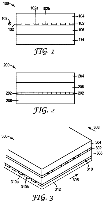
Touch sensor layer constructions and methods of making such constructions are described.
US 9,784,449 B2 · Inventors: Margolin; Jed
Sheet 1 of 66 from the published document. All sheets in the USPTO PDF
This invention relates to the field of sensing flames in equipment using a combustion burner such as gas furnaces by using the electrical properties of flames. In a first group of embodiments flame rectification is used to cause distortion of a signal having a selected waveform. A harmonic of the distorted waveform is detected thereby providing flame proof. In a second group of embodiments flame rectification is used as a mixer to cause two signals having selected waveforms to produce sum and difference signals. The sum and/or difference signals are detected thereby providing flame proof.
Field of Invention This invention relates to the field of sensing flames in equipment such as gas furnaces using the electrical properties of flames. In such equipment it is necessary to sense (detect) that a flame is actually being produced when fuel is being provided to a combustion burner. Otherwise the unburnt fuel will continue to flow and build up, and may cause asphyxiation and if it finds an ignition source may explode. The term “combustion” means the process of oxidation of molecules of combustible substances that occurs readily at high temperatures with the release of energy. It is accompanied by that phenomenon which is called “flame” and by the generation of “heat energy”. The term “flame” means a self-sustaining propagation of a localized combustion zone at subsonic velocities. The term “combustion burner” means a device used for facilitating the combustion of a gas or a liq
1 of 66 drawing sheets so far from the published document, cropped to the drawing. Every sheet is in the USPTO PDF.
What the patent claimed, word for word. All of it is now free to use.
Field of Invention
This invention relates to the field of sensing flames in equipment such as gas furnaces using the electrical properties of flames. In such equipment it is necessary to sense (detect) that a flame is actually being produced when fuel is being provided to a combustion burner. Otherwise the unburnt fuel will continue to flow and build up, and may cause asphyxiation and if it finds an ignition source may explode.
The term “combustion” means the process of oxidation of molecules of combustible substances that occurs readily at high temperatures with the release of energy. It is accompanied by that phenomenon which is called “flame” and by the generation of “heat energy”. The term “flame” means a self-sustaining propagation of a localized combustion zone at subsonic velocities. The term “combustion burner” means a device used for facilitating the combustion of a gas or a liquid. The term “burner” means the same as combustion burner. The term “flame conductivity” means the electrical conductivity of a flame. The unit of conductivity is the “mho”. The term “flame conduction” means the same as flame conductivity. The term “flame resistance” is the reciprocal of flame conductivity. The unit of resistance is the Ohm. The term “flame rectification” means the property of flames to preferentially conduct electrical current depending on the direction of the electrical current. The term “flame electrode” means an electrically conducting material immersed in a flame (when a flame is present), and which is electrically isolated from the combustion burner (except for a flame) and which may be electrically connected to something outside of the flame. The term “flame probe” means the same as flame electrode. The term “flame rod” means the same as flame electrode. The term “flame sensor” means the same as flame electrode. The term “flame battery” means the voltage produced between a combustion burner and a flame electrode that is immersed in the flame produced by the combustion burner. The term “flame voltage” means the same as flame battery. The term “flame proof” means proof that a flame exists. The term “proof of flame” means the same as flame proof. The term “plasma” means a collection of gas where a large proportion of atoms have enough energy that their electrons have been stripped away, creating ions, and that the proportion of ions to intact atoms is high enough that Coulomb forces have a significant effect on the behavior of the collection of gas. The ions creating the plasma will be termed “plasma ions”. The term “chemical ions” means reactive molecules, or atoms, that have unpaired electrons. The term “chemi-ionization” means the process by which molecules, or atoms, come to have unpaired electrons. The terms “chemi-ions”, “radical”, and “free radical” mean the same as chemical ions. The term “thermionic emission” means the emission of electrons from the surface of an electrically conducting material when the material is heated to a temperature high enough to overcome the work function of the material, typically several electron volts. One electron volt is equal to approximately 1.602×10.sup.−19 Joules. The term “high impedance buffer” means a buffer whose input impedance is substantially higher than the impedance of the circuit it is intended to buffer. The terms “amplifier” and “buffer” will mean the same thing regardless of the gain of the circuit. The term “mixer” means a circuit that accepts two signal inputs and forms an output signal at the sum and difference frequencies of the two signals. The terms “mixing” and “to mix” mean using a mixer. When two signals are mixed in this manner it is also called heterodyning. The term “flame good indicator” will mean the same as “indicator”. The term “symmetrical square wave” means a square wave having a duty cycle of substantially 50%.
Prior Art
The electrical properties of flames comprise flame conduction, flame rectification, and the generation of a flame voltage between a metal burner and a flame rod.
U.S. Pat. No. 1,688,126 Method of and Apparatus for Control of Liquid Fuel Burners issued Oct. 16, 1928 to R. F. Metcalfe, assigned to Socony Burner Corporation {IDS Cite 1}. This patent teaches using the resistance of the flame for providing flame proof. It uses only the flame resistance, not flame rectification. Two electrodes are used (Contacts 7 and 8 in Metcalfe FIG. 1). From page 3, right column, lines 70-79: One of the main features of my invention is to utilize the phenomenon of the variation in resistance to the passage of sparks between any two contacts. The resistance in this instance is offered by the gases within the combustion chamber 4. I have found that I may take advantage of this phenomenon by utilizing the resistance to the passage of sparks between the points of the spark-plug employed for igniting the combustible mixture. In Metcalfe FIG. 1 the secondary of Spark Coil 56 is used to produce an ignition spark between contacts 7 and 8. During ignition the resistance of the burning gas is reflected back through to the primary winding of Spark Coil 56. Since a spark coil has a high ratio of turns between the primary and secondary windings the resistance reflected back through the primary is much lower than if it was used directly. This lower resistance through the primary winding is apparently low enough to operate a relay (Electro-Magnet 58). It appears that the spark is continuously produced. Later patents note that the continuous spark causes radio interference and they teach systems that do not require a continuous spark.
U.S. Pat. No. 2,112,736 Flame Detector issued Mar. 29, 1938 to William D. Cockrell, assigned to General Electric {IDS Cite 2}. This patent teaches using flame rectification for providing flame proof. Cockrell FIG. 1 shows an embodiment using one electrode
with the burner
used as the return. The AC used in the flame sensing circuit is used only for the flame sensing circuit and is not also used as a spark igniter. See Page 1, left column, line 41-Page 2, right column, line 15.
U.S. Pat. No. 2,136,256 Furnace Control System issued Nov. 8, 1938 to A. L Sweet, assigned to General Electric Company {IDS Cite 3}. This patent also teaches using flame rectification for providing flame proof and is an improvement on 2,112,736. Sweet introduces an additional electrode to allow the flame rectification circuit to operate reliably with an oil-fueled flame. See Page 1, left column, line 4-Page 2, left column line 2.
However, the wires from the two electrodes are surrounded by a shield. See Page 6, left column lines 36-55 and Sweet FIG. 4 . Shielding the wires reduces the stray coupling from the mains power (60 Hz in the U.S.). It is possible that the problem Sweet has solved is the stray coupling from the mains power which may be made worse by the use of oil as a fuel.
U.S. Pat. No. 3,301,307 Device for detecting the configuration of a burning flame issued Jan. 31, 1967 to Kazuo Kobayashi, et al, assigned to Ngk Insulators Ltd {IDS Cite 4}. This patent teaches the use of the flame battery for flame proof. From Column 2, lines 3-15: The principle of the invention is based on, first of all, the recognition of the phenomenon that a negative potential to ground is produced in an electric conductor when it is located in a burning flame. It seems that such a phenomenon is due to an exchange of electric charges between the conductor acting as an electrode and ionized molecules through the contact surface of said electrode with the flame depending upon differences of temperature and degree of combustion between the inner and outer parts of said burning flame and atmospheric conditions. The phenomenon is inherent to flames and a potential difference in the order of 2-10 volts or more has been obtained by experiments.
U.S. Pat. No. 4,082,493 Gas Burner Control System issued Apr. 4, 1978 to Dahlgren, assigned to Cam-Stat, Incorporated {IDS Cite 5}. This patent also teaches the use of the flame battery for flame proof. See Dahlgren FIG. 2 and Column 3, lines 32-42.
U.S. Pat. No. 8,310,801 Flame sensing voltage dependent on application issued Nov. 13, 2012 to McDonald, et al., assigned to Honeywell {IDS Cite 6}. This patent teaches using flame rectification for providing flame proof. The claimed novelty is that in order to avoid excessive component stress, energy consumption, increased electrical noise, and contamination build-up, when accuracy is critical a higher voltage is used. Once a flame has been established, the AC voltage may be adjusted to a lower level. See Column 2, lines 10-44.
However, McDonald has not produced evidence that the use of a high AC voltage causes excessive build-up of contamination on a flame rod, increased energy consumption that generates extra heat, or that it stresses associated electronic circuitry. The commonly accepted theory is that contamination of the flame rod is caused by the products of combustion, notably carbon. Also, any extra heat that might be produced would not be wasted because the purpose of a furnace is usually to produce heat. It is likely that the real value of McDonald's system is that, since his high voltage AC is produced electronically, it is isolated from the AC mains. This is in contrast to the commonly used practice of using the un-isolated AC mains for the flame rod voltage. Since the combustion burner is typically used as the electrical return path for the flame rod and is electrically connected to the equipment cabinet (which is required to be grounded) this requires that mains neutral and mains ground be connected. According to the National Electrical Code this may only be done (and is required to be done) at the service entrance to the building and no place else. As a result, an electrical connection problem outside the furnace at the service entrance may cause a flame sensing circuit to malfunction even though there is no problem in the furnace itself. Since McDonald's invention produces the high voltage AC for the flame rod electronically (and is isolated from the mains) it would not be subject to this failure mode. Current Practice for Providing Flame Proof
The current practice for providing flame proof uses the two general properties of flames: the optical properties of flames and the electrical properties of flame.
Flames have optical properties that range from infrared to ultraviolet. These optical properties are discussed in U.S. Pat. No. 6,404,342 Flame detector using filtering of ultraviolet radiation flicker issued Jun. 11, 2002 to Planer, et al. and assigned to Honeywell {IDS Cite 7}. From Column 1, lines 21-32: Another type of flame detector relies on directly on the radiation provided by the flame. However, the mere presence of visible or IR radiation does not necessarily indicate an active flame. Walls of combustion chambers tend to radiate visible and IR energy for a period of time after flame is lost. It was found, however, that active flames have characteristic flicker frequencies in the IR, visible, and UV wavelengths. Typically, an active flame flickers in the 5 to 15 hz. range (as well as in higher frequencies) in all of these wavelength bands. Heated refractory walls or glowing particles have different flicker frequencies or none at all. So flicker in these wavelengths can be used to reliably indicate flame. The electrical properties of flames comprise flame conduction, flame rectification, and the generation of a flame voltage between a metal burner and a flame rod. These properties are exemplified in the prior art already presented. However, there is another electrical property of flames, namely that flames may absorb microwave radiation. See IDS Cite 8 Prediction and Measurement of Electron Density and Collision Frequency in a Weakly Ionised Pine Fire by Mphale, Mohan, and Heron. This electrical property appears to be used only for research and not for providing flame proof in operating equipment. Processes that May Produce or Contribute to the Electrical Properties of Flames
The investigation of the electrical properties of flames goes back to at least the early 1900s with the work of J. J. Thomson. See IDS Cite 9 for an excerpt from Thomson's work Conduction of Electricity Through Gases (1903, 1906) Chapter IX Ionization in Gases from Flames. Thomson begins the chapter with an observation that modern researchers in the field should take notice of. Writing in 1903 he observed: 121. It has been known for more than a century that gases from flames are conductors of electricity; a well-known application of this fact—the discharge of electricity from the surface of a non-conductor by passing a flame over It—was used by Volta in his experiments in Contact Electricity. We shall not attempt to give any historical account of the earlier experiments on this subject, because the conditions in these experiments were generally such that the interpretation of the results obtained is always exceedingly difficult and often ambiguous: the reason of this is very obvious—to investigate the electrical conditions of the flame wires are generally introduced, these become incandescent and so at once add to the electrical phenomena in the flame the very complicated effects we have been discussing in the last chapter.
The electrical properties of flames comprise flame conduction, flame rectification, and the generation of a flame voltage between a metal burner and a flame rod (flame battery). FIG. 1 shows a representative Combustion Burner ( 1 ), Flame ( 2 ), and Flame Rod ( 3 ). FIG. 2 is a representative electrical model of the electrical properties of FIG. 1 . Experiments will show that this is an AC model and that the flame battery is an integral part of Flame Diode D ( 23 ). In the absence of a flame ( FIG. 3 ) the representative electrical model is an open circuit ( FIG. 4 ).
There are several processes that may account for the electrical properties of flames. Is Flame a Plasma?
An important question to ask in order to understand what causes the electrical properties of flames is: Is flame a plasma?
From the article About Plasmas from the Coalition For Plasma Science Plasma and Flames—The Burning Question {IDS Cite 10}:
The Medium Answer: Whether a plasma exists in a flame depends on the material being burned and the temperature. A plasma is an ionized gas. However, not all ionized gases are plasmas. In order for an ionized region of a flame to be plasma, it must contain enough charged particles for that region to exhibit unique electrical properties of plasma, which are distinctly different from properties of other states of matter. Since the density of charged particles increases as temperature increases, a high-temperature region in a flame may contain enough charged particles to be a plasma. Lower-temperature flames contain no significantly ionized regions and no plasma. An example of a flame with relatively low temperatures is the flame of a household wax candle. The maximum temperature is less than 1,500 degrees Celsius, too low for much ionization to occur. However, some flames are much hotter than that. For example, in some burning mixtures of acetylene (made up of hydrogen and carbon) and oxygen, at a pressure of one atmosphere, the peak temperature in a flame has been measured to exceed 3,100 degrees Celsius. Thus, the flame from a wax candle (less than 1,500 degrees Celsius) is not a plasma. The flame from acetylene and oxygen (around 3,100 degrees Celsius) probably is a plasma, at least in part.
The flame of a typical wax candle burns at approximately 1,500 degrees Celsius at its hottest. The flames of interest here are those produced by the hydrocarbon fuels natural gas and propane. Natural gas (methane) is CH.sub.4. Propane is C.sub.3H.sub.8. In a typical burner using the oxygen in the air as the oxidizer, and producing a premixed flame, the flame temperature of natural gas is approximately 1,980 degrees Celsius. The temperature of a premixed propane flame is about the same. So, we need to look further.
The article Plasma Fundamentals and Applications by Dr. I. J. Van der Walt, Senior Scientist Necsa contains a chart {IDS Cite 11, PDF page 8} that graphs the electron temperature verses electron density for various processes. Flames are toward the bottom of the graph for electron density. It is unlikely that the flame from natural gas or propane contains any appreciable plasma. We should discuss temperature. The temperature of a gas is a measure of the average kinetic energy of the gas molecules as they collide with each other and with the walls of the container. If the container walls are rigid the molecules will bounce off. With a flame the walls are the atmosphere, and the boundary between the flame and the atmosphere is a function of atmospheric pressure. The collisions between the molecules in the flame and the molecules in the atmosphere produce diffusion. It is this diffusion that makes diffusion flames possible. An example of a diffusion flame is the flame produced by a wax candle. The other type of flame is called a premixed flame and is where the oxidizer (the oxygen in the atmosphere) is mixed with the fuel before combustion. Premixed flames produce a more stoichiometric mixture than diffusion flames, so they burn more completely (and hotter). For this reason most furnaces use premixed flames. Chemical Ions
The preceding doesn't mean there isn't a useable density of ions in a flame. There is, but they aren't plasma ions. They are chemical ions, or chemi-ions.
The oxidation of methane is: CH.sub.4+2O.sub.2, flame or spark.fwdarw.CO.sub.2+H.sub.2O+energy However, Nature does not like to make or break more than one chemical bond at a time. So there are a number of intermediate species produced between CH.sub.4+2O.sub.2 and CO.sub.2+H.sub.2O+energy. And it's a large number. An excellent reference is Introduction to Combustion by Stephen R. Turns. See IDS Cite 12, page 108, PDF page 3. Turns reports (citing GRI Mech 2.11) that at least 325 intermediate reactions have been found in the combustion of methane (natural gas). See IDS Cite 12, page 159, PDF bottom of page 5. A portion of the list is reproduced in FIG. 14 . The presence of nitrogen in some of the equations indicates that the methane is being burned using air. By volume dry air contains 78.09% nitrogen, 20.95% oxygen, 0.93% argon, 0.039% carbon dioxide, and small amounts of other gases. Nitrogen compounds form starting at about 800 degrees Celsius, much lower than the temperature at which methane burns. The various species of nitrogen are generally represented as NO.sub.x which is toxic and considered a pollutant. Additional Components in Natural Gas and Propane
There are more components in natural gas and propane. Since methane and propane are odorless, an odorant is added to make leaks easy to detect. The odorant most often used is mercaptan, which is methanethiol (also known as methyl mercaptan). Mercaptan is an organic compound with the chemical formula CH.sub.3SH (also written as CH.sub.4S). The sulfur no doubt produces the putrid smell. The flue of a gas furnace does not have this smell because the mercaptan is broken down and forms sulfur oxides (SO.sub.2 and SO.sub.3). As long as the temperature of the flue gas is above the gas dewpoint temperature the sulfur oxides will vent into the air where they may combine with water to form H.sub.2SO.sub.4 (sulfuric acid). Furnaces that recapture heat from the flue gas may cause the flue gas to drop below the gas dewpoint temperature resulting in H.sub.2SO.sub.4 precipitating in the equipment. {IDS Cite 13}
Also, in the data reported by Turns a number of the formulas contain the letter “M”. “M” is not an element. In chemistry the letter “M” is used to represent an alkali metal. {IDS Cite 14}.
From Wikipedia {IDS Cite 15}:
The alkali metals are the elements in Group 1 (1A). They are lithium, sodium, potassium, rubidium, cesium, and francium. These elements are best marked by their reactivity. Physically they are soft, shiny (when freshly prepared) solids with low melting points; they conduct electricity well. They all have one valence electron that they lose easily to almost any electronegative substance. Why are there alkali metals in natural gas?
Some are there naturally and some are there because of hydraulic fracturing, or “fracking”. See U.S. Pat. No. 4,317,487 Method of recovering oil and other hydrocarbon values from subterranean formations issued Mar. 2, 1982 to Merkl, and assigned to Molecular Energy Research Company, Inc. See Column 2, line 59-Column 3, line 11. {IDS Cite 16}
There are even more components in the natural gas and propane used in furnaces and other equipment because Natural Gas is not 100% methane (CH.sub.4) and Propane is not 100% propane (C.sub.3H.sub.8).
Natural Gas—From Turns pages 657-659 {IDS Cite 12—Turns pages 657-659; PDF pages 22-24}
Although there are no industry or governmental standards for pipeline natural gas, contracts between producers and pipeline companies define general ranges of composition and other properties [26, 27]. Processing removes solid matter (e.g., sand), liquid hydrocarbons, sulfur compounds, water, nitrogen, carbon dioxide, helium, and any other undesirable compounds to meet contract specifications. The removal of sulfur compounds results in making an acidic, i.e., sour, gas sweet. Table 17.11 shows typical values, or ranges, of important properties of pipeline gas based on the General Terms and Conditions of a set of geographically dispersed pipeline companies in the United States and Canada. The composition of natural gas varies widely depending upon the source. Examples for U.S. sources of natural gas are shown in Table 17.12. Compositions for natural gases from a variety of non-U.S. sources are provided in Table 17.13. The following table (Table 1) is an abridged reproduction of Table 17.12 from Turns. The complete Turns Table 17.12 has been reproduced as FIG. 15 .
TABLE-US-00001 TABLE 1 (Abridged Turns Table 17.12) Table 17.12 Composition (mol %) and properties of natural gas from sources in the United States [28].sup.a Location CH.sub.4 C.sub.2H.sub.6 C.sub.3H.sub.8 C.sub.4H.sub.10 CO.sub.2 N.sub.2 Alaska 99.6 — — — — 0.4 Birmingham, 90.0 5.0 — — — 5.0 East Ohio.sup.b 94.1 3.01 0.42 0.28 0.71 1.41 Kansas City, 84.1 6.7 — — 0.8 8.4 Pittsburgh, 83.4 15.8 — — — 0.8 Thus, in Turns' sample natural gas ranged from a high of 99.6% in Alaska to a low of 83.4% in Pittsburgh. Propane
There are three basic grades of propane: HD5, HD10, and Commercial Grade. From IDS Cite 17 (Propane101):
HD-5 Propane HD5 grade propane is “consumer grade” propane and is the most widely sold and distributed grade of propane in the U.S. market. HD5 is the highest grade propane available to consumers in the United States and is what propane companies ordinarily sell to their customers. What does HD5 propane mean in terms of specification to an ordinary consumer? It means that the propane is suitable and recommended for engine fuel use, which was the original purpose of the HD5 grade propane specification. HD5 spec propane consists of: Minimum of 90% propane Maximum of 5% propylene—propylene is used in the manufacture of plastics Other gases constitute the remainder (iso-butane, butane, methane, etc.) HD-10 Propane and Commercial Propane HD10 propane is a grade below HD5 and is commonly found in California. HD10 grade propane allows up to 10% propylene in the propane/propylene mixture and is still labeled as “propane”. Because propylene is used in creating plastics, HD10 can possibly create problems in some engines and vehicle applications. Propylene can cause engine components to “gum” or stick during operation. However, HD 10 spec propane works just fine in domestic and commercial propane powered appliances. The only problem that may be encountered in using HD-10 propane involves its use as an engine fuel (vehicles, forklifts, etc.). Commercial grade propane and HD10 grade propane are sometimes used interchangeably due to the fact that both grades are sub-HD5 spec product and do not meet the standards of engine grade propane. Refineries use commercial propane in their processes and fractionation of chemicals for end use in numerous industries. Although commercial grade propane can be used in a manner similar to that of HD10 propane, it is not used in vehicle applications. The article The Truth About Propane {IDS Cite 18} goes a little farther. After discussing the Gas Processors' Association standard for propane, GPA 2140
which was the original HD5 standard, it then addresses the commercial grade of propane: By contrast, since 1975, oil refineries were able to take advantage of the definition of propane in the ASTM (American Society for Testing and Materials) standard, ASTM Standard D1835, to market oil refining “odds and ends,” known by chemical engineers as “slop,” because they could claim that the slop fit the definition of “commercial grade” propane: any hydrocarbon mixture that held a flame. With HD5 and HD10 you have an idea of what you are getting. Apparently, commercial grade propane is the hotdog of the oil refining business.
The preceding paragraphs provide persuasive evidence that the temperature of the flame produced by the combustion of natural gas or propane is not high enough to produce an appreciable amount of plasma. Instead, the flame is a soup of chemical ions. This matters because the electrical properties of plasma may be different from the electrical properties of chemical ions.
In addition:
1. There are a large number of different chemical ions because there are a large number of intermediate chemical species;
2. The types of intermediate chemical species and their amounts will be affected by the exact composition of the gas (natural gas or propane) and there is a fairly wide latitude in the standards for the composition of natural gas and propane.
3. Gas obtained through fracking may contain a greater amount of alkali metals which may affect the electrical properties of the flame produced by the combustion of the gas. Gas Pressure
A flame is not a bunch of chemical ions and free electrons in a sealed container. Gas and air come into the burner under pressure and combusts, producing chemical ions and free electrons which then form a large number of short-lived intermediate species ending with CO.sub.2, H.sub.2O, NOx, sulfur oxides, and probably more types of molecules. Then they go shooting off into the atmosphere. This process continues as long as there is new gas (unless the flame goes out for some reason). Because the gas pressure moves the gas molecules before combustion it is likely that after combustion this gas pressure gives the chemical ions and electrons a group velocity. But because different ions may have different masses, and because of the much smaller mass of the electron, the negative chemical ions and the electrons may get to the flame rod first. And the free electrons are not just from chemical ionization. Thermionic Emission
As J. J. Thomson observed {IDS Cite 9}: “ . . . to investigate the electrical conditions of the flame wires are generally introduced, these become incandescent and so at once add to the electrical phenomena in the flame the very complicated effects we have been discussing in the last chapter.” The effects caused by the incandescent wires are called Thermionic Emission. Thermionic emission is the emission of electrons from the surface of an electrically conducting material when the material is heated to a temperature high enough to overcome the work function of the material, typically several electron volts. One electron volt is equal to approximately 1.602×10.sup.−19 Joules. Thermionic emission comes not just from the flame rod but also from the burner, assuming the burner is metal. (Some of the early flame experiments used a quartz burner.) In systems with two flame rods the second flame rod is also a source of thermionic emission.
Thermionic emission was discovered (or maybe rediscovered) by Thomas Edison while trying to discover the reason for breakage of lamp filaments and uneven blackening (darkest near one terminal of the filament) of the bulbs in his incandescent lamps. He placed an extra wire inside the bulb and discovered that current would only flow in one direction. However, he used this discovery only as a governor to control the output of dynamos. See IDS Cite 19—U.S. Pat. No. 307,031 Electrical indicator issued Oct. 21, 1884 to T. A. Edison. From page 1, lines 16-29: I have discovered that if a conducting substance is interposed anywhere in the vacuous space within the globe of an incandescent electric lamp, and said conducting substance is connected outside of the lamp with one terminal, preferably the positive one, of the incandescent conductor, a portion of the current will, when the lamp is in operation, pass through the shunt-circuit thus formed, which shunt includes a portion of the vacuous space within the lamp. This current I have found to be proportional to the degree of incandescence of the conductor or candlepower of the lamp.
John Fleming improved upon Edison's invention. See IDS Cite 20—U.S. Pat. No. 803,684 Instrument for converting alternating electric currents into continuous current issued Nov. 7, 1905 to J. A. Fleming, assigned to Marconi Wireless Telegraph Company of America.
From Fleming, page 1, lines 11-37:
This invention relates to certain new and useful devices for converting alternating electric currents, and especially high-frequency alternating electric currents or electric oscillations, into continuous electric currents for the purpose of making them detectable by and measurable with ordinary direct-current instruments, such as a “mirror-galvanometer” of the usual type or any ordinary direct-current ammeter. Such instruments as the latter are not affected by alternating electric currents either of high or low frequency, which can only be measured and detected by instruments called “alternating current” instruments of special design. It is, however, of great practical importance to be able to detect feeble electric oscillations, such as are employed in Hertzian-wave telegraphy by an ordinary movable coil or movable needle mirror-galvanometer. This can be done if the alternating current can be “rectified”—that is, either suppressing all the constituent electric currents in one direction and preserving the others or else by changing the direction of one of the sets of currents which compose the alternating current so that the whole movement of electricity is in one direction. Fleming had a reason for improving on Edison's work because he was looking for an improved detector for Hertzian waves (radio waves). To be fair to Edison, in 1884 there were no manmade Herztian waves to be detected. Hertz did not begin his experiments until 1888 and Tesla and Marconi did not begin their experiments in radio until a few years later. Chemical Ions as an Electrolyte
The chemical ions in a flame may act much like the chemical ions in the electrolyte used in electrolytic rectifiers, electrolytic capacitors, and batteries. Technically, an electrolyte is a compound that ionizes when dissolved in suitable ionizing solvents such as water. {IDS Cite 21} For the purposes of this discussion we will assume that the compound is dissolved in a suitable solution. Fleming's patent {IDS Cite 20} makes reference to an electrochemical rectifier. From Page 1, lines 38-52: There are well-known forms of mechanical rectifier; also, there is a well-known form of electrochemical rectifier, depending on the fact that when a plate of carbon and aluminium is placed in any electrolyte which yields oxygen on electrolysis an electric current can only pass through this cell in one direction if below a certain voltage. Both these forms of rectifier are, however, inapplicable for high-frequency currents. I have found that the aluminium-carbon cell will not act with high-frequency currents. Another name for an electrochemical rectifier is an electrolytic rectifier or an electrolytic cell. From the 1917 Dissertation Counter Electromotive Force in the Aluminum Rectifier by Albert Lewis Fitch, page 15: {IDS Cite 22}:
I. INTRODUCTION. THE anomalous action of aluminum in the electrolytic cell was first discovered by Wheatstone in 1855. Soon after this, Buff found that an electrolytic cell one electrode of which was aluminum would rectify the alternating current. Among the other men who have been interested in this cell may be mentioned Ducretet,.sup.1 Hutin and Leblanc,.sup.2 Montpellier,.sup.3 Nodon,.sup.4 Guthe,.sup.5 Greene,.sup.6 and Schulze..sup.7 The latter has perhaps done the largest amount of work of any. His articles have appeared from time to time in a number of magazines. The earlier experimenters with this cell confined themselves to the study of aluminum but later investigation.sup.7 has shown that many other metals possess this same property to a greater or less degree. Among these may be mentioned iron, nickel, cobalt, magnesium, cadmium, tin, bismuth, zirconium, tantalum, etc. A great many electrolytes may be used in the rectifier. The most commonly used are the alums, phosphates, and carbonates; however Greatz and Pollak.sup.8 have shown that any electrolyte which will liberate oxygen on electrolysis may be used more or less satisfactorily. It has been found that the ability of the cell to rectify alternating current depends upon the current density at the aluminum anode,.sup.9 the inductance and resistance of the circuit,.sup.10 and its temperature..sup.11 The cell works best when the current density is high and the inductance, resistance, and temperature are low.
The electrolytic rectifier led to the electrolytic capacitor. From U.S. Pat. No. 1,077,628 Electrolytic condenser issued Nov. 4, 1913 to Mershon {Ref 23} Page 1, lines 40-50:
The electrolytic condenser, like the electrolytic rectifier, depends for its action upon the properties of the film which may be formed electrolytically upon the surface of aluminum, tantalum, magnesium and other metals when immersed in certain electrolytes and subjected to the electric current. Inasmuch as the electrolytic rectifier is concerned in my invention, and as its explanation leads up to that of the condenser, it will be first described.
Mershon then presents a detailed explanation of the electrolytic rectifier followed by a detailed explanation of his electrolytic condenser (capacitor).
Both electrolytic rectifiers and electrolytic capacitors have two electrodes with an electrolyte between them. One electrode is termed the anode. While the other electrode is termed the cathode its purpose is only to provide electrical contact with the electrolyte which is the real cathode.
Indeed, modern aluminum electrolytic capacitors have the capability of acting as rectifiers (but not very good ones). From Nichicon, a leading manufacturer of electrolytic capacitors in General Descriptions of Aluminum Electrolytic Capacitors, 1-1 Principles of Aluminum Electrolytic Capacitors {IDS Cite 24, page 1}: An aluminum electrolytic capacitor consists of cathode aluminum foil, capacitor paper (electrolytic paper), electrolyte, and an aluminum oxide film, which acts as the dielectric, formed on the anode foil surface. A very thin oxide film formed by electrolytic oxidation (formation) offers superior dielectric constant and has rectifying properties. When in contact with an electrolyte, the oxide film possesses an excellent forward direction insulation property. Together with magnified effective surface area attained by etching the foil, a high capacitance yet small sized capacitor is available. As previously mentioned, an aluminum electrolytic capacitor is constructed by using two strips of aluminum foil (anode and cathode) with paper interleaved. This foil and paper are then wound into an element and impregnated with electrolyte. The construction of aluminum electrolytic capacitor is illustrated in FIG. 1-1. {Nichicon FIG. 1-1 is reproduced as FIG. 16 } Since the oxide film has rectifying properties, a capacitor has polarity. If both the anode and cathode foils have an oxide film, the capacitors would be bipolar (nonpola) type capacitor. {Emphasis added} Thus, even modern electrolytic capacitors show their origins as rectifiers. And Nichicon's paper says that electrolytes are not limited to liquid electrolytes. Solid electrolytes may also be used. Therefore, even though the chemical ions in a flame have a much lower density than the chemical ions in an electrolyte they may nonetheless play some part in the electrical properties of a flame.
Both electrolytic rectifiers and electrolytic capacitors have two electrodes and an electrolyte between them. Another device that has two electrodes and an electrolyte between them is the battery. (Technically, a battery has more than one battery cell but the term battery is frequently used to describe a single battery cell.) A battery cell has two electrodes with an electrolyte between them. The electrolyte can be liquid, solid, a paste, a gel, etc. What makes a battery cell different from an electrolytic capacitor? From the article: Batteries and electrochemical capacitors {IDS Cite 25}: Batteries can generally store significantly more energy per unit mass than ECs, as shown in FIG. 1a, because they use electrochemical reactions called faradaic processes. Faradaic processes, which involve the transfer of charge across the interfaces between a battery's electrodes and electrolyte solution, lead to reduction and oxidation, or redox reactions, of species at the interfaces. When a battery is charged or discharged, the redox reactions change the molecular or crystalline structure of the electrode materials, which often affects their stability, so batteries generally must be replaced after several thousand charge-discharge cycles. Another way to look at it is that in a battery the electrolyte and the electrodes are chemically changed. (In rechargeable batteries the change can be mostly reversed by sending current through it.) In modern electrolytic capacitors the two electrodes are made of the same material, such as aluminum, so they have the same galvanic response. Hence, it is not a battery. As noted previously, in an electrolytic capacitor the purpose of one of the electrodes (the cathode electrode) is to provide an electrical contact to the electrolyte which is the real cathode. Also note that the electrodes in Fleming's electrolytic rectifier {IDS Cite 20} are carbon and aluminum but the electrolyte has to have the property that it produces oxygen on electrolysis. Therefore, once again, even though the chemical ions in a flame have a much lower density than the chemical ions in an electrolyte they may nonetheless play some part in the electrical properties of a flame. If they do, then the materials used in the combustion burner and the flame rod will have an effect on the voltage produced by the flame battery.
There is one more device that has two electrodes and an electrolyte: the electroplating cell. In an electroplating cell an electric current from anode to cathode causes the material in the anode to be deposited onto the cathode. {IDS Cite 26}
It is telling that the metals used in the electrodes are called “rectifier metals.” {IDS Cite 27: U.S. Pat. No. 3,956,080 Coated valve metal article formed by spark anodizing issued May 11, 1976 to Hradcovsky, et al.; Column 2 lines 10-48}
The current involved in flame sensing circuits is so small (generally <1 uA.) that it is unlikely that any significant electroplating is going on. Even if a small amount of electroplating does occur it is unlikely that it would have an effect on the electrical properties of the flame. Summary of the Processes that May Produce or Contribute to the Electrical Properties of Flames
A. The Electrical Properties of Flames Comprise:
The description continues in the full USPTO document.
About 6,454 words. The USPTO PDF has it with every drawing.
Fees are due 3.5, 7.5 and 11.5 years after grant. This patent expired on October 10, 2025, so the fee marked "not paid" was the one that went unpaid.
Flame Sensing System
Filed Jun 2014 · published Dec 2015Flame sensing system
Filed Jun 2014 · granted Oct 2017Earlier publications, parents and continuations. None of them can still be enforced, or this patent would not be listed.
Prior art cited by the examiner or applicant. Useful when you check your own idea for novelty.
Everything on this page comes from the documents linked above.