 Lapsed, fee not paid4 drawings
Consumer Products · US 9,783,273 B2
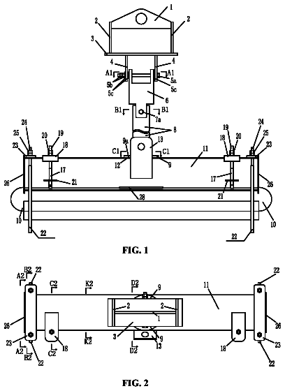
Carrying device for side-scan sonar
A carrying device for a side-scan sonar, including a suspension rod, a hanging rack, and a flange.
US 9,784,294 B2 · Assignee: PENTEL KABUSHIKI KAISHA · Inventors: Uchida; Hideo et al.
Sheet 1 of 46 from the published document. All sheets in the USPTO PDF
A clip attaching structure includes a clip supporting portion which protrudes on an outer circumferential surface of a main body, a clip, and a coil spring. The clip is configured to be rotatable with respect to a fulcrum at which the clip is engaged with the clip supporting portion. The convex portion is inserted into an inside of one end portion of the coil spring, and the other end portion of the coil spring abuts against the outer circumferential surface of the main body. A base portion of the convex portion has an outer diameter greater than an inner diameter of the coil spring, and a tip end portion of the convex portion has an outer diameter smaller than the inner diameter of the coil spring.
A clip attaching structure is known in the related art in which a clip is linked to a main body, such as a long shaft tube which is elongated in a back-and-forth direction to be freely rotatable around a fulcrum or the like, a tip end side of the clip abuts against an outer circumferential surface of the shaft tube or the like, a back end side of the clip is constantly repulsed to be separated from the outer circumferential surface of the shaft tube or the like. In the clip attaching structure, a coil spring is used as a repulsive member. For example, in PTL 1, a structure is disclosed in which an end portion of a coil spring is fitted to a concave portion which is provided in one of a clip inner surface and a clip supporting body, and the other end portion of the coil spring abuts against the other plane surface among the clip inner surface and the clip supporting body. CITATION LIST Pa
1 of 46 drawing sheets so far from the published document, cropped to the drawing. Every sheet is in the USPTO PDF.
What the patent claimed, word for word. All of it is now free to use.
The present invention relates to a clip, and particularly relates to a clip attaching structure in which the clip is linked to a main body or the like of a writing instrument to be freely rotatable around a fulcrum, a tip end side of the clip abuts against an outer circumferential surface of the main body or the like, and a back end side of the clip is constantly repulsed to be separated from the outer circumferential surface of the main body or the like.
A clip attaching structure is known in the related art in which a clip is linked to a main body, such as a long shaft tube which is elongated in a back-and-forth direction to be freely rotatable around a fulcrum or the like, a tip end side of the clip abuts against an outer circumferential surface of the shaft tube or the like, a back end side of the clip is constantly repulsed to be separated from the outer circumferential surface of the shaft tube or the like.
In the clip attaching structure, a coil spring is used as a repulsive member.
For example, in PTL 1, a structure is disclosed in which an end portion of a coil spring is fitted to a concave portion which is provided in one of a clip inner surface and a clip supporting body, and the other end portion of the coil spring abuts against the other plane surface among the clip inner surface and the clip supporting body. CITATION LIST Patent Literature
[PTL 1] JP-A-2010-83069 SUMMARY OF INVENTION Technical Problem
In a structure which is disclosed in PTL 1, a concave portion is provided to cover an outer circumferential surface of a coil spring. However, in the structure of the PTL 1, since an outer diameter of the coil spring increase when the coil spring contracts in accordance with an opening and closing operation of a clip, an inner circumferential surface of a spring fitting concave portion and the outer circumferential surface of the coil spring come into contact with each other, and frictional resistance is generated. As a result, there is a concern that the opening and closing operation of the clip is disturbed.
Here, PTL 1 discloses that an opening portion side of the concave portion is formed so as to not come into contact with the outer circumferential surface of the coil spring so that frictional resistance when the coil spring expands and contracts decreases. However, since the spring fitting concave portion is provided to cover the outer circumferential surface of the coil spring, the outer circumferential diameter of the spring fitting concave portion becomes larger, and furthermore, since the clip or a clip supporting body which is provided with the spring fitting concave portion becomes larger, and design of the product is restricted. Solution to Problem
According to the invention, there is provided a clip attaching structure, including: a clip supporting portion which is protruded on an outer circumferential surface of a main body; a clip which is engaged with the clip supporting portion; and a coil spring which biases one end portion of the clip in a direction of being separated from the outer circumferential surface of the main body, in which the clip is configured to be rotatable with respect to a fulcrum at which the clip is engaged with the clip supporting portion, in which the coil spring is provided being closer to the one end portion of the clip than the fulcrum, and biases the clip so that the other end portion of the clip abuts against the outer circumferential surface of the main body, in which the clip has a convex portion which is protruded towards the outer circumferential surface of the main body, from a surface of the clip which faces the outer circumferential surface of the main body, in which the convex portion is inserted into an inside of one end portion of the coil spring, and in which the other end portion of the coil spring abuts against the outer circumferential surface of the main body.
The clip attaching structure may be configured so that the outer circumferential surface of the main body has a plane portion, and the other end portion of the coil spring abuts against the plane portion.
The clip attaching structure may be configured so that an outer diameter of a base portion of the convex portion is greater than an inner diameter of the coil spring, and an outer diameter of a tip end portion of the convex portion is smaller than the inner diameter of the coil spring.
When the clip rotates by a predetermined amount in a direction in which the other end portion of the clip is separated from the outer circumferential surface of the main body, a tip end of the convex portion may abut against the outer circumferential surface of the main body.
A slit may be formed in the convex portion along a longitudinal direction of the clip.
A shape of the convex portion in a cross section which is orthogonal to a direction in which the convex portion is protruded may be a circular shape.
The main body may be a shaft tube of a writing instrument.
A slider may be provided in the main body in order to operate a pen tip of the writing instrument.
The clip attaching structure may be configured so that a plurality of sliders for operating a pen tip of the writing instrument are provided in the main body, and the clip supporting portion is provided in at least one of the sliders. Advantageous Effects of Invention
In the present invention, the clip attaching structure, includes: the clip supporting portion which is provided to be protruded on the outer circumferential surface of the main body; the clip which is engaged with the clip supporting portion; and the coil spring which biases the one end portion of the clip in a direction of being separated from the outer circumferential surface of the main body, in which the clip is configured to be freely rotatable with respect to the fulcrum at which the clip is engaged with the clip supporting portion, in which the coil spring is provided being closer to the one end portion of the clip than the fulcrum, and biases the clip so that the other end portion of the clip abuts against the outer circumferential surface of the main body, in which the clip has the convex portion which is protruded towards the outer circumferential surface of the main body, from the surface of the clip which faces the outer circumferential surface of the main body, in which the convex portion is inserted into the inside of the one end portion of the coil spring, and in which the other end portion of the coil spring abuts against the outer circumferential surface of the main body. Accordingly, since frictional resistance of the coil spring in a clip opening and closing operation can be reduced, opening and closing operability of the clip is improved. In addition, there is no discomfort even when the clip is used in a main body which has a small outer shape dimension (which is thin), and not only a degree of freedom of a design of a clip main body, but also a degree of freedom of a design of the product itself can be improved.
FIG. 1 is a perspective view illustrating a configuration of Embodiment 1 of the present invention.
FIG. 2 is a longitudinal sectional view illustrating the configuration of Embodiment 1 of the present invention.
FIG. 3 is a partially enlarged view of FIG. 2 .
FIG. 4 is a sectional view along line A-A of FIG. 2 .
FIG. 5 is a sectional view along line B-B of FIG. 2 .
FIG. 6 is a view taken in the direction along arrow C of FIG. 2 .
FIG. 7 is a partially enlarged longitudinal sectional view illustrating a configuration of Embodiment 2 of the present invention.
FIG. 8 is a partially enlarged longitudinal sectional view illustrating an operation of Embodiment 2 of the present invention.
FIG. 9 is a front view of an entire multi-core writing instrument illustrating a configuration of Embodiment 3 of the present invention.
FIG. 10 is a longitudinal sectional view along line D-D of FIG. 9 .
FIG. 11 is a front view of the entire multi-core writing instrument in a state where a tip member portion 42 is protruded.
FIG. 12 is a longitudinal sectional view along line F-F of FIG. 11 .
FIG. 13 is a front view of a slidable case 27 .
FIG. 14 is a rear view of the slidable case 27 .
FIG. 15 is a lateral sectional view along line G-G of FIG. 14 .
FIG. 16 is a longitudinal sectional perspective view along line H-H of FIG. 14 .
FIG. 17 is a front view of a back shaft 26 .
FIG. 18 is a longitudinal sectional view along line I-I of FIG. 17 .
FIG. 19 is a right side view of a slider 29 .
FIG. 20 is a rear view of the slider 29 .
FIG. 21 is a right side view of a clip slider 30 .
FIG. 22 is a rear view of the clip slider 30 .
FIG. 23 is a bottom view of the clip slider 30 .
FIG. 24 is a lateral sectional view along line E-E of FIG. 9 .
FIG. 25 is a right side view of the slider 29 in an embodiment where a detachable member 45 is configured.
FIG. 26 is a rear view of the slider 29 in the embodiment where the detachable member 45 is configured.
FIG. 27 is a top view of the slider 29 in the embodiment where the detachable member 45 is configured.
FIG. 28 is a longitudinal sectional view along line J-J of FIG. 27 .
FIG. 29 is a right side view of the clip slider 30 in the embodiment where the detachable member 45 is configured.
FIG. 30 is a rear view of the clip slider 30 in the embodiment where the detachable member 45 is configured.
FIG. 31 is a top view of the clip slider 30 in the embodiment where the detachable member 45 is configured.
FIG. 32 is a longitudinal sectional view along line K-K of FIG. 31 .
FIG. 33 is a view of an external appearance of a sharp unit 41 in a state of being fitted to the detachable member 45 .
FIG. 34 is a partially enlarged perspective view of FIG. 9 .
FIG. 35 is a partially enlarged view of FIG. 10 .
FIG. 36 is a partially enlarged longitudinal sectional view illustrating an operation of Embodiment 3 of the present invention.
FIG. 37 is a partially enlarged view of FIG. 12 .
FIG. 38 is a right side view of a clip main body 33 .
FIG. 39 is a front view of the clip main body 33 .
FIG. 40 is a rear view of the clip main body 33 .
FIG. 41 is a longitudinal sectional view along line L-L of FIG. 39 .
FIG. 42 is a perspective view illustrating a first modification example of Embodiment 1 and Embodiment 2 of the present invention.
FIG. 43 is a perspective view illustrating a second modification example of Embodiment 1 and Embodiment 2 of the present invention.
FIG. 44 is a perspective view illustrating a third modification example of Embodiment 1 and Embodiment 2 of the present invention.
FIG. 45 is a lateral sectional view along line E-E of FIG. 9 according to a modification example of Embodiment 3 of the present invention.
FIG. 46 is a perspective view of a clip slider main body 31 according to the modification example of Embodiment 3 of the present invention.
FIG. 47 is a perspective view illustrating a lower side of the clip main body 33 according to the modification example of Embodiment 3 of the present invention.
FIG. 48 is a perspective view illustrating an upper side of the clip main body 33 of FIG. 47 .
A configuration of a clip of the present invention will be described based on Embodiment 1 with reference to FIGS. 1 to 6 . FIG. 1 is a perspective view illustrating a configuration of Embodiment 1 of the present invention. FIG. 2 is a longitudinal sectional view. FIG. 3 is a partial enlarged longitudinal sectional view. FIG. 4 is a sectional view along line A-A of FIG. 2 . FIG. 5 is a sectional view along line B-B of FIG. 2 . FIG. 6 is a view of arrow C of FIG. 2 .
In addition, the present Embodiment is described by using a clip attaching structure in which the clip is attached to a shaft tube (main body) of a writing instrument, but the main body is not limited to the shaft tube of the writing instrument if the clip is necessary. For example, the main body may be an erasing instrument or a coating instrument. The writing instrument may be a ballpoint pen, a sharp pencil, a marking pen, or a fountain pen. The erasing instrument may be a correction pen or an eraser. The coating instrument may be glue or a cosmetic tool, such as eyeliner or an eyebrow pencil. In addition, a shape of the main body is not limited to a cylindrical shape, and for example, may be a shape of a square cylinder, a columnar shape, and a shape of a prism.
As illustrated in FIGS. 1 and 2 , a main body 1 is a long member which is elongated in a back-and-forth direction. A pen tip which is not illustrated is provided at a front end of the main body 1 . A clip supporting portion 2 is integrally provided in an outer circumferential portion on a back side of the main body 1 . A clip main body 4 is rotatably (i.e., pivotably) engaged with the clip supporting portion 2 . On left and right side surfaces of the clip supporting portion 2 , a columnar fulcrum shaft 3 is provided to be protruded in a perpendicular direction with respect to a longitudinal direction of the main body 1 .
The clip main body 4 is also a long member which is elongated in the back-and-forth direction. The clip main body 4 is configured to be freely rotatable with respect to a fulcrum at which the clip main body 4 is engaged with the clip supporting portion 2 . A lateral cross section of the clip main body 4 is formed in a substantial U shape, and a right side plate portion 5 and a left side plate portion 6 are provided to face the left and right side surfaces of the clip supporting portion 2 . A fulcrum hole 7 is provided to be open in the right side plate portion 5 and the left side plate portion 6 , and constitutes a rotating (i.e., pivoting) fulcrum 8 which is engaged with the fulcrum shaft 3 and supports the clip main body 4 to be freely rotatable.
Furthermore, as illustrated in FIG. 4 , in the vicinity of an end portion of the fulcrum shaft 3 , a tapered surface portion 3 a which narrows in a direction of being separated from the main body 1 is formed. When the fulcrum hole 7 of the clip main body 4 is assembled to the fulcrum shaft 3 , the tapered surface portion 3 a makes it easy to perform an assembly operation.
As illustrated in FIGS. 1 to 3 , a coil spring 11 is provided between the outer circumferential portion of the main body 1 and the clip main body 4 . The coil spring 11 biases one end portion of the clip main body 4 in the direction of being separated from an outer circumferential surface of the main body 1 . In addition, the coil spring 11 is provided being closer to the one end portion side of the clip main body 4 than a fulcrum so that the other end portion of the clip main body 4 abuts against the outer circumferential surface of the main body 1 .
In the outer circumferential portion of the main body 1 on the back side rather than the clip supporting portion 2 , a plane portion 10 is provided to face an inner bottom surface 9 of the clip main body 4 . One end portion 12 of the coil spring 11 abuts against the plane portion 10 .
In addition, the clip main body 4 is provided with a cylindrical convex portion 14 which is protruded towards the plane portion 10 of the main body 1 , from a back side portion of the inner bottom surface 9 of the clip main body 4 which faces the outer circumferential surface of the main body 1 . The other end portion 13 of the coil spring 11 is inserted from the outside to cover the convex portion 14 . In other words, the convex portion 14 is inserted into the inside of the other end portion 13 of the coil spring 11 . The one end portion 12 which abuts against the plane portion 10 and the other end portion 13 which abuts against the inner bottom surface 9 constitute a repulsive portion 15 . In other words, by a bias force of the coil spring 11 , a back side portion (one end portion of the clip main body 4 ) is repulsed more than the rotating fulcrum 8 of the clip main body 4 to be separated from the outer circumferential surface of the main body 1 , and a front side portion (the other end portion of the clip main body 4 ) is repulsed more than the rotating fulcrum 8 of the clip main body 4 to abut against the outer circumferential surface of the main body 1 via the rotating fulcrum 8 . In this configuration, by pressing the back side portion more than the rotating fulcrum 8 of the clip main body 4 towards a shaft line from an outer diameter direction of the main body 1 against the bias force of the coil spring 11 , the clip can perform an opening and closing operation and rotate so that the front side portion is separated more than the rotating fulcrum 8 of the clip main body 4 from the outer circumferential surface of the main body 1 via the rotating fulcrum 8 .
Furthermore, in the present Embodiment, the clip main body 4 is configured of a material which is made of a colored opaque resin, and is molded by injection molding or the like. However, if a configuration of the present invention is possible, it does not particularly matter what material is used and any material, such as a metal, may be used.
In addition, as described above, by inserting the coil spring 11 from the outside to cover the convex portion 14 , the coil spring 11 is prevented from being separated from an attaching position to the clip main body 4 while in use.
Furthermore, as the coil spring 11 contracts according to the opening and closing operation of the clip main body 4 , an inner diameter and an outer diameter of the coil spring 11 increase. However, at this time, an interval between the outer circumferential surface of the convex portion 14 and the inner circumferential surface of the coil spring 11 widens, and a contact area between the convex portion 14 and the coil spring 11 decreases. As a result, the frictional resistance decreases, and a comfortable opening and closing operation is possible.
In the present Embodiment, the one end portion 12 of the coil spring 11 is in a free state, and can be freely displaced. For this reason, the one end portion 12 of the coil spring 11 slidingly abuts against the outer circumferential surface of the main body 1 to be freely movable along the outer circumferential surface of the main body 1 .
For this reason, when assembling the writing instrument, regarding the clip main body 4 side, it is necessary to match the position of the other end portion 13 of the coil spring 11 to the position of the convex portion 14 . However, regarding the main body 1 side, it is not necessary to match the position of the one end portion 12 of the coil spring 11 to a certain position. For this reason, assembly of the writing instrument becomes easy. In addition, when the opening and closing operation of the clip main body 4 is performed, the one end portion 12 of the coil spring 11 can freely move, and excessive resistance is unlikely to be applied to the coil spring 11 . For this reason, durability of the coil spring 11 is improved.
In addition, in the present Embodiment, the outer circumferential surface against which the one end portion 12 of the coil spring 11 abuts is the plane portion 10 . A contact area with respect to the plane portion 10 of the coil spring 11 increases, a force which is applied from the coil spring 11 with respect to the outer circumferential surface of the main body 1 is dispersed, and a scratch or a recess is unlikely to be generated in an external appearance of the outer circumferential surface of the main body 1 .
In the present Embodiment, on the outer circumferential surface of the main body 1 , a part against which the one end portion 12 of the coil spring 11 abuts is a plane (plane portion 10 ), but as described in a first modification example illustrated in FIG. 42 , this part may be a curved surface. In an example illustrated in FIG. 42 , the one end portion 12 of the coil spring 11 is allowed to be able to abut against a curved part of the outer circumferential surface of the cylindrical main body 1 .
In addition, in FIG. 42 , the part against which the one end portion 12 of the coil spring 11 abuts is a curved surface which is curved in a circumferential direction of the cylindrical main body 1 . However, the part may be a curved surface which is curved in a direction of a shaft, or may be a curved surface which is curved in the circumferential direction and in the shaft direction, and each part can be configured of an arbitrary curved surface.
In addition, the outer diameter of the convex portion 14 can be smaller than the inner diameter of the coil spring 11 . In this case, since the contact area between the outer circumferential surface of the convex portion 14 and the inner circumferential surface of the coil spring 11 is further reduced, an aspect which is desirable for a more comfortable opening and closing operation is realized.
Furthermore, a tapered shape in which the outer diameter of the convex portion 14 gradually decreases towards the tip end portion which is provided to be protruded is also possible. In this case, the outer circumferential surface of the convex portion 14 and the inner circumferential surface of the coil spring 11 are separated from each other as being close to the vicinity of the tip end portion, and not only the aspect which is desirable for a more comfortable opening and closing operation, but also improvement of separability as a falling-out taper which is provided in molding in a case of molding the clip main body 4 by injection molding, can be improved.
In addition, since the convex portion 14 is included in the coil spring 11 as described above, the outer diameter of the coil spring 11 becomes the outermost diameter of the repulsive portion 15 , and the size of the repulsive portion 15 can be small. Furthermore, it is also possible to make the clip main body 4 which accommodates the repulsive portion 15 in the substantial U-shaped inner surface portion small. In particular, it is possible to reduce the width of the clip main body 4 , and to improve a degree of freedom of a design of the clip main body 4 .
Furthermore, the convex portion 14 is illustrated in a substantial cylindrical shape in order to prevent a recess (sink) which is generated by molding contraction caused by a material when molding is performed in FIG. 3 , but may have a substantial columnar shape. In addition, a shape of a cross section (lateral cross section) which is orthogonal to a protruding direction is also not limited to a circular shape, and various shapes, such as not only a shape of a geometrical plane, including a polygonal shape, a shape of a cross, a star-shaped polygonal shape, but also a shape, including a shape which has a partial arc, can be employed. However, a shape may be appropriately selected in consideration of manufacturing cost or the like.
In addition, in the present Embodiment, an example in which the clip supporting portion 2 is provided on the outer circumferential surface of the main body 1 is described, but the present invention is not limited thereto. As described in a second modification example illustrated in FIG. 43 , the clip main body 4 may be attached to the clip supporting portion 2 which is provided in a slider for operating a pen tip of the writing instrument, and the clip main body 4 may be slidable together with the slider. This structure will be described in detail as Embodiment 3 later.
In addition, the clip attaching structure of the present Embodiment may be provided in a multi-core writing instrument which has a plurality of refills, such as a ballpoint pen unit, a sharp unit, or a stylus pen unit, contained therein, as described in a third modification example illustrated in FIG. 44 .
Next, a clip structure of the present invention will be described based on Embodiment 2 with reference to FIGS. 7 and 8 . FIG. 7 is a partially enlarged longitudinal sectional view illustrating a configuration of Embodiment 2 of the present embodiment. FIG. 8 is a partially enlarged longitudinal sectional view illustrating an operation of Embodiment 2 of the present embodiment.
Since the configuration is the same as that of Embodiment 1 except for a shape of the concave portion, the same shape and the material will be described in detail. In addition, in the present Embodiment, similarly to Embodiment 1, a modification example illustrated in FIGS. 42 to 44 can be employed.
In Embodiment 2, a large-diameter portion 17 of which the diameter is slightly greater than an inner circumferential diameter of the coil spring 11 is provided so that the outer circumferential surface of a base portion which is close to the inner bottom surface 9 of a convex portion 16 is pressure-welded to the inner circumferential surface of the coil spring 11 . The end portion of the coil spring 11 is held in a state of being lightly pressed-in to the substantial entire circumference of the large-diameter portion 17 . The length of the large-diameter portion 17 in the protruding direction is substantially the same dimension as a line diameter of the coil spring 11 , and a tip end side in the protruding direction rather than the large-diameter portion 17 is a small-diameter portion 18 of which the outer diameter is smaller than that of the large-diameter portion 17 . By allowing the small-diameter portion 18 to be separated from the inner circumferential surface of the coil spring 11 , only a coiled seat portion 19 which is provided in the end portion of the coil spring 11 is pressure-welded. In this configuration, since it is possible not only to prevent a positional shift of the coiled seat portion 19 of the coil spring 11 during the clip opening and closing operation, but also to prevent the convex portion 16 and the coil spring 11 from coming into contact with each other during a process of the opening and closing operation of the clip main body 4 , a comfortable opening and closing operation is possible.
In the present Embodiment, a shape of the cross section which is orthogonal to the protruding direction of the convex portion 16 is preferably a substantial circular shape. By making the shape of the cross section of the convex portion 16 a substantial circular shape, the end portion (coiled seat portion 19 ) of the coil spring 11 is pressure-welded in the substantial entire circumference of the large-diameter portion 17 (a lightly pressed-in state is held). Accordingly, it is possible to prevent a positional shift of the other end portion 13 of the coil spring 11 during the clip opening and closing operation. In addition, it is possible to further prevent the small-diameter portion 18 of the convex portion 16 and the coil spring 11 from coming into contact with each other during the process of the opening and closing operation of the clip, and to perform a more comfortable opening and closing operation of the clip. Furthermore, it is possible to more reliably hold the coil spring 11 substantially integrally with respect to the convex portion 16 when assembling the clip main body 4 to the clip supporting portion 2 , and the assembly work is further improved.
Furthermore, it is desirable that the shape of the cross section in the large-diameter portion 17 of the convex portion 16 is a substantial circular shape, and an arbitrary shape may be employed in the small-diameter portion 18 .
In addition, as the coiled seat portion 19 which is provided in the end portion of the coil spring 11 as described above is pressure-welded to the large-diameter portion 17 of the convex portion 16 , by inserting the coil spring 11 onto the convex portion 16 from the outside and substantially integrally holding the coil spring 11 during assembly, the coiled seat portion 19 can be engaged with the clip supporting portion 2 . As a result, there is also an effect of preventing the coil spring 11 from being disengaged and lost during the assembly work.
Furthermore, since the one end portion 12 of the coil spring 11 abuts against the plane portion 10 of the main body 1 as described above, when the coil spring 11 is assembled, it is not necessary to match the position to the position of the main body 1 , and there is also an effect of performing the assembly work more simply.
In addition, as described above, since the clip main body 4 and the coil spring 11 are substantially integrated with each other during assembly, and engagement with the clip supporting portion 2 is performed from a centrifugal direction of the main body 1 , the one end portion 12 of the coil spring 11 substantially perpendicularly abuts against the plane portion 10 of the main body 1 . In this configuration, since it is possible to prevent the generation of a scratch in the longitudinal direction of the main body 1 to the plane portion 10 by the one end portion 12 of the coil spring 11 during assembly, there is an effect of excellently retaining the external appearance of the product. Furthermore, in the process of engagement, the right side plate portion 5 and the left side plate portion 6 of the clip main body 4 easily widen in a leftward and rightward direction by the tapered surface portion 3 a (refer to FIG. 4 ) of the fulcrum shaft 3 . According to this, the fulcrum hole 7 of the clip main body 4 can be easily engaged with the fulcrum shaft 3 .
Furthermore, the convex portion 16 is illustrated as a substantial cylindrical shape for preventing a sink when molding is performed in FIG. 7 , but may be a substantial columnar shape. In addition, the shape of the cross section (lateral cross section) which is orthogonal to the protruding direction is not limited to a circular shape, and various shapes, such as not only a shape of a geometrical plane, including a polygonal shape, a shape of a cross, a star-shaped polygonal shape, but also a shape, including a shape which has a partial arc, can be employed. Furthermore, the shapes of the large-diameter portion 17 and the small-diameter portion 18 can also be a combination of various sectional shapes, for example, a circular shape can be employed as a shape of a cross section of the large-diameter portion 17 , and a polygonal shape can be employed as a shape of a cross section of the small-diameter portion 18 . However, in consideration of manufacturing cost or the like, a shape may be appropriately selected.
Next, a configuration of the clip of the present invention will be described based on Embodiment 3 with reference to FIGS. 9 to 41 . In Embodiment 3, the multi-core writing instrument which has a plurality of refills, such as a ballpoint pen unit, a sharp unit, or a stylus pen unit, contained therein is described, and the clip of the present invention is configured in the slider in which a front end is linked to a back end of the refill. FIG. 9 is a view illustrating the external appearance of the entire multi-core writing instrument which has a configuration of Embodiment 3 of the present invention. FIG. 10 is a longitudinal sectional view.
A shaft main body 23 in the present Embodiment includes a front shaft 25 , a back shaft 26 , and a slidable case 27 . In the present Embodiment, a main body 24 includes the shaft main body 23 , a slider 29 which is disposed in a window hole 26 a ( FIG. 24 ) of the back shaft 26 , or a clip slider main body 31 ( FIG. 24 ) which will be described later.
As illustrated in FIG. 10 , in an inner diameter portion of the front shaft 25 , a conical portion 25 a of which the diameter gradually decreases towards the tip end side is formed. In addition, at the tip end of the front shaft 25 , a protruded hole 25 b in which a writing portion (pen tip 38 ) of a ballpoint pen unit 37 or a tip member portion 42 of a sharp unit 41 appears is formed.
Here, in addition to the ballpoint pen unit 37 or the sharp unit 41 , a unit which includes the stylus pen unit or the like which can operate an eraser unit that sends out an eraser or a smartphone, and is embedded in the shaft main body 23 , is generally called a refill 28 .
The front shaft 25 considers visibility or designability of the refill 28 which is disposed inside thereof, and is configured of one component. However, a clip which is made of a rubber-shaped elastic body may be inserted, or a clip which is made of a rubber-shaped elastic body may cover the front shaft by means, such as two-color molding or multicolor molding. Accordingly, a comfortable grip, ease of writing, and fatigue reduction are improved.
The front shaft 25 and the back shaft 26 are attached to be detachable by screwing, and the slidable case 27 is attached to a back end portion of the back shaft 26 . In the present Embodiment, on a front surface of an outer circumference of the slidable case 27 , engagement projections 27 a for engagement with the back shaft 26 are provided at an equivalent interval ( FIG. 13 ). In addition, the engagement projection 27 a is engaged with the back end portion of the window hole 26 a ( FIGS. 17, 18, and 24 ) which is provided on the front surface of the outer circumference of the back shaft 26 . Accordingly, in the multi-core writing instrument which is combined with the sharp unit 41 as described in the present Embodiment, a slide distance of the slidable case 27 when a sharp core L is sent out by pressing the slidable case 27 is effectively utilized in the window hole 26 a , and the length of the shaft main body 23 is suppressed.
In addition, a cut-out portion 27 b is provided only at one location on the outer circumferential surface of the slidable case 27 ( FIG. 14 ). An apex 31 a ( FIG. 21 ) of the clip slider main body 31 of the slider (clip slider 30 ) which constitutes the clip of the present invention which will be described later is provided to be engageable. According to this, without damaging a shape of the clip slider 30 , it is possible to slide similarly to the other slider 29 .
Furthermore, in the present Embodiment, the ballpoint pen unit 37 is linked to the front end of the slider 29 , and the sharp unit 41 is linked to the front end of the slider 29 . Here, the clip slider 30 together with the slider 29 is a place for an operation of exchanging a writable state where the pen tip is protruded out of the front end of the main body 1 and an unwritable state where the pen tip is retraced in from the front end of the main body 1 . A user can switch the writable state and the unwritable state by operating the clip slider 30 together with the slider 29 .
As illustrated in FIG. 19 , a cut-out portion 29 b is provided in a direction of a shaft center at a back end of a pressing portion 29 a of the slider 29 , and covers the engagement projection 27 a ( FIG. 13 ) of the slidable case 27 which is engaged with the back end portion of the above-described window hole 26 a and makes the engagement projection 27 a invisible from the external appearance.
In addition, as illustrated in FIG. 21 , the apex 31 a of the clip slider main body 31 exists in the clip slider 30 , and is engaged with the cut-out portion 27 b which is in one location in the slidable case 27 of the above-described FIG. 14 .
In a state where the back shaft 26 and the slidable case 27 are engaged with each other as illustrated in FIG. 10 above, a front half portion 27 c ( FIG. 16 ) of the slidable case 27 is disposed at a back end inner portion of the back shaft 26 , and meanwhile, a back half portion of the slidable case 27 is protruded from a back end opening portion 26 b of the back shaft 26 . The protruded back half portion of the slidable case 27 is considered a knocking portion 27 d , and the entire slidable case 27 slides back and forth with respect to the back shaft 26 by a knocking operation.
When the multi-core writing instrument can perform writing as all of the refills which are contained in the multi-core writing instrument are protruded from the protrusion hole of the front shaft, or when the multi-core writing instrument can perform an operation of sending out the core by further moving the slider back and forth after the refill is protruded from the protrusion hole of the front shaft, the slidable case 27 and the back shaft 26 may be fixed separately, and in addition, may be integrated. A case of a writable state as all of the refills which are contained in the multi-core writing instrument are protruded from the protrusion hole of the front shaft is, for example, a case where all of the refills are ballpoint pen units, or a case where the refills are ballpoint pen units and stylus pen units. In addition, the core is not limited to the sharp core of a sharp unit, and for example, may be the eraser of an eraser unit.
As illustrated in FIGS. 14 to 16 , the inside of the slidable case 27 crosses over the entire length, and is divided by a beam-shaped dividing wall 27 e to split a radial direction. In addition, the slidable case 27 is made in a shape of a tube with a bottom, but a front side from an intermediate portion does not have a tube portion 27 f , and is in an opened state in the radial direction. Specifically, a cut-out portion 27 g of which a shape of a cross section is a shape of a fan is formed, and the cut-out portion 27 g is in an opened state. In other words, by using the cut-out portion 27 g as a slidable surface, the slider 29 or the clip slider 30 slides in the slidable case 27 . The pressing portion 29 a ( FIGS. 10 and 11 ) of the slider 29 and a clip supporting portion 31 b of the clip slider main body 31 are protruded to the outside from the window hole 26 a of the back shaft 26 , and the slider 29 and the clip slider 30 slide in the window hole 26 a of the back shaft 26 .
In a state where the pen tip 38 is retracted, the slider 29 is pushed to a back side by a repulsive force of a repulsive member 35 , and an arc-shaped abutting portion 29 c ( FIG. 20 ) of the slider 29 abuts against a slider abutting portion 27 h ( FIG. 13 ) of the slidable case 27 . Planes of the slider 29 and the slider abutting portion 27 h of the slidable case 27 may come into contact with each other, but in the present Embodiment, arcs thereof are brought into contact with each other. Accordingly, a concentration of stress which is caused by an impulsive force to the slidable case 27 of the slider 29 by the repulsive force of the repulsive member 35 is mitigated, and the possibility of generation of breakage is reduced.
In addition, a similar structure is also employed in the clip slider 30 , and an arc-shaped abutting portion 31 c ( FIGS. 21 and 22 ) of the clip slider main body 31 abuts against a clip slider abutting portion 27 i ( FIG. 14 ) of the slidable case 27 . Accordingly, an effect which is equivalent to that of the above-described slider 29 is obtained.
The description continues in the full USPTO document.
About 7,147 words. The USPTO PDF has it with every drawing.
Fees are due 3.5, 7.5 and 11.5 years after grant. This patent expired on October 10, 2025, so the fee marked "not paid" was the one that went unpaid.
ATTACHMENT STRUCTURE FOR CLIP
Filed Feb 2014 · published Jan 2016Attachment structure for clip
Filed Dec 2014 · granted Oct 2017Earlier publications, parents and continuations. None of them can still be enforced, or this patent would not be listed.
Prior art cited by the examiner or applicant. Useful when you check your own idea for novelty.
Everything on this page comes from the documents linked above.