Patent Yard Sign in
Lapsed, fee not paid

Apparatus and methods for treating bone structures, tissues and ducts using a narrow gauge cannula system

US 9,782,572 B2 · Assignee: Nordson Corporation · Inventors: Saab; Mark A. et al.

USPTO PDF

Overview

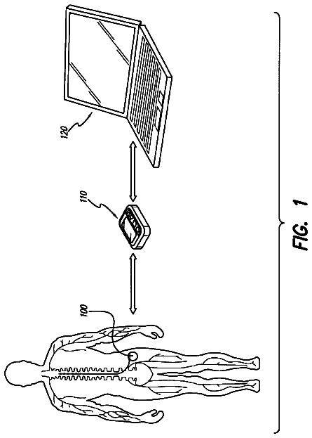
Sheet 1 of 56 from the published document. All sheets in the USPTO PDF

Abstract From the patent

Systems, apparatus and methods are disclosed for medical treatment comprising bone access and dilatation and/or cavity creation or enlargement using a narrow gauge, preferably 11-gauge or smaller, cannula wherein a catheter/expandable element assembly meeting medical protocols for such procedures is designed, adapted and fabricated to fit through the interior of the associated 11-gauge or smaller cannula, and further including apparatus and methods for wrapping and/or folding the expandable element either before or after a procedure to reduce its profile to fit through the cannula.

Why it's free to use

  • The USPTO Official Gazette of December 9, 2025 lists it as expired on October 10, 2025 for an unpaid maintenance fee.
  • It isn't on any reinstatement notice published since.
  • Its 1 US relative has also lapsed, expired or never issued.
  • We check US rights only. Check foreign counterparts before selling abroad.
FiledMarch 13, 2013
GrantedOctober 10, 2017
Expired (fee)October 10, 2025
Application number13/800197
Classification (CPC)A61B17/8855 +7 more
Length64 claims · 105 pages

Background From the patent

A number of diseases, illnesses and other medical conditions are treatable at least in part by dilatation of a bone, tissue or duct. For example, medical conditions and/or physical injuries can lead to or predispose a bone to deformity, such as a fracture. A familiar example is osteoporosis, in which bones lose calcium and break more easily. The human spinal column, comprised of interconnected vertebrae or vertebral bodies, has proven to be especially susceptible to the effects of osteoporosis. A vertebral body weakened by osteoporosis can fracture from a fall, or simply during routine activities. When a vertebral body fractures, it can collapse and change the shape of the spine. The damaged portion of the spine becomes shorter, and the rest of the spine above the broken vertebral body bends forward. As additional vertebral fractures occur, the spine shortens further, increasingly forcin

Drawings 56

1 of 56 drawing sheets so far from the published document, cropped to the drawing. Every sheet is in the USPTO PDF.

Figures as described

  • FIG. 10A is configured substantially similar to that shown in FIG. 1A except that the inflation/deflation port in FIG
  • FIG. 13A is otherwise shown configured substantially similar to that of FIG
  • FIG. 34A is configured somewhat similar to that shown in FIG. 10A except that in FIG. 34A there is a fixed inner shaft and the balloon is wrapped by rotating the outer shaft

Claims 64 total, 6 independent

What the patent claimed, word for word. All of it is now free to use.

  1. 1
    Independent claimA catheter/expandable element assembly with proximal and distal assembly ends for medical applications comprising: a single catheter shaft having a long axis and proximal and distal catheter portions; an expandable element comprising a balloon portion suitable for treating vertebral fractures and related Kyphoplasty-type procedures with a balloon interior and also comprising a proximal neck portion butt-jointed and bonded at a bond juncture to the distal catheter portion wherein the balloon portion and the bond juncture can be passed through an 11-gauge or smaller diameter medical cannula before inflation of the balloon portion and after deflation of the balloon portion after a treatment procedure; a fluid passageway extending from the proximal catheter portion to the balloon interior; and, a mandrel element extending through the distal catheter portion and the expandable element wherein a distal mandrel portion beginning inside the catheter shaft and extending through the expandable element is of a reduced diameter relative to a proximal mandrel portion.
  2. 2
    An assembly according to claim 1 further comprising a passive balloon tensioning and/or balloon wrapping device.
  3. 3
    An assembly according to claim 1 further comprising an 11-gauge or smaller diameter cannula wherein at least one end of the balloon portion extends into or completely through said cannula when the balloon portion is positioned in a cavity to be dilated.
  4. 4
    A catheter/expandable element assembly according to claim 1 additionally wherein the proximal neck portion is butt-jointed by a bonding procedure selected from the group consisting of an adhesive bonding procedure, a solvent bonding procedure and a thermal bonding procedure to the distal catheter portion.
  5. 5
    A catheter/expandable element assembly according to claim 1 wherein the assembly has a maximum diameter of less than 0.092 inches at the bond juncture.
  6. 6
    A catheter/expandable element assembly according to claim 1 wherein the fluid passageway has a generally circular cross-section with a fluid passageway diameter defined by an inner wall of the catheter shaft and wherein the fluid passageway diameter on either side of the bond juncture is substantially the same size as an inner diameter of the distal catheter portion at the bond juncture.
  7. 7
    A catheter/expandable element assembly according to claim 1 wherein an outer diameter of the distal catheter portion and an outer diameter of the proximal neck portion at the bond juncture are substantially the same size so as to form a smooth, uninterrupted outer surface at the bond juncture.
  8. 8
    A catheter/expandable element assembly according to claim 7 wherein an inner diameter of the distal catheter portion, a diameter of the fluid passageway, and an inner diameter of the proximal neck portion at the bond juncture are substantially the same size.
  9. 9
    A catheter/expandable element assembly according to claim 1 wherein the only catheter shaft is a single lumen catheter.
  10. 10
    A catheter/expandable element assembly according to claim 1 wherein an inner diameter of the distal catheter portion, a diameter of the fluid passageway, and an inner diameter of the proximal neck portion at the bond juncture are substantially the same size, and also wherein an outer diameter of the distal catheter portion and an outer diameter of the proximal neck portion at the bond juncture are substantially the same size so as to form a smooth, uninterrupted outer surface at the bond juncture.
  11. 11
    A catheter/expandable element assembly according to claim 1 wherein the mandrel element is a floating mandrel that extends through the distal catheter portion and through the expandable element to a distal portion of the expandable element, wherein the floating mandrel comprises a distal mandrel end bonded to the expandable element and a free, unbonded proximal mandrel end.
  12. 12
    An assembly according to claim 1 further comprising an active balloon tensioning and/or balloon wrapping device.
  13. 13
    A system for carrying out a medical dilatation and/or a cavity creation, enlargement or treatment procedure at an internal body site comprising a catheter/expandable element assembly according to claim 1 in combination with an 11-gauge or smaller diameter cannula having a cannula interior for delivering the expandable element from outside the body, through the cannula interior, to the desired internal body site and, following a treatment procedure, for withdrawing the deflated expandable element from the body site through the cannula interior.
  14. 14
    A system according to claim 13 wherein the cannula interior is free of any lubricant and also wherein no lubricant is applied to the catheter/expandable element assembly.
  15. 15
    A method for carrying out a medical treatment that includes a dilatation and/or a cavity creation, enlargement or treatment procedure using a system according to claim 13, the method comprising the steps of: (A) positioning the cannula in a body location so that a distal end of the cannula is proximate to the intended treatment site; (B) inserting at least the expandable element portion of the assembly through the cannula interior to position the expandable element in the interior of a bone or body site without the use of any lubricants; (C) inflating the balloon portion of the expandable element inside the interior of the bone or body site to a size and/or inflation pressure and for a time sufficient to complete the treatment; (D) deflating the balloon portion of the expandable element; and, (E) withdrawing the expandable element including the deflated balloon portion of the assembly through the cannula interior without the use of any lubricants.
  16. 16
    A method for carrying out a medical treatment that includes a dilatation and/or a cavity creation, enlargement or treatment procedure that is performed with an expandable conforming balloon using a catheter/expandable element assembly according to claim 1, the method comprising the steps of: (A) inserting at least the expandable element portion of the assembly through the interior of a previously-placed 11-gauge or smaller diameter cannula to position the expandable element including a distal tip of the expandable element in the interior of a bone or body site; (B) inflating the balloon portion of the expandable element inside the interior of the bone or body site to a size and/or inflation pressure and for a time sufficient to complete the treatment; (C) deflating the balloon portion of the expandable element; and (D) withdrawing the expandable element including the deflated balloon portion of the assembly through the interior of the 11-gauge or smaller diameter cannula.
  17. 17
    A method according to claim 16 additionally comprising a step of stretching, folding and/or wrapping the expandable element following step (B) and prior to step (D).
  18. 18
    Independent claimA catheter/expandable element assembly with proximal and distal assembly ends for medical applications comprising a catheter shaft having a long axis and proximal and distal catheter portions, an expandable element comprising a balloon suitable for treating vertebral fractures and related Kyphoplasty-type procedures with a balloon interior and also comprising a proximal neck portion butt-jointed at a bond juncture to the distal catheter portion, and a fluid passageway extending from the proximal catheter portion to the balloon interior, the assembly being characterized by: (A) a balloon having the following properties: (i) the balloon has expansion properties that enable the expansion of the balloon inside a targeted bone region to press against and compress surrounding cancellous bone, or to move cortical bone to a prefracture or other desired condition, or both, prior to failure of the balloon wall, when the balloon is expanded to an elongation at least 50% greater than before expansion; (ii) the balloon has shape properties that enable the balloon to predictably deform during expansion to an expanded shape whereby a desired expanded shape inside the targeted bone region can be selected based on prior analysis of the morphology of the targeted bone region; and, (iii) the balloon has toughness properties that enable the balloon to resist surface abrasion, tearing and puncture when it is expanded and in contact with cancellous bone, including the properties of: a Taber Abrasion value of less than approximately 200 mg loss; and/or an Elmendorf Tear Strength of at least approximately 150 lb.-ft./in.; and/or a Shore Hardness of less than approximately 75 D; and, (B) the assembly also being characterized by one or more of the following features: (a) the expandable element comprises a balloon which can be stretched, folded and/or wrapped to a maximum diameter of less than 0.092 inches before inflation of the balloon and after deflation of the balloon after a treatment procedure; (b) the assembly includes both a stretched, folded and/or wrapped balloon and a bond juncture between the catheter shaft and the proximal neck portion that will fit through the interior of a standard 11-gauge medical cannula before inflation of the balloon and after deflation of the balloon after a treatment procedure; (c) the assembly includes both a stretched, folded and/or wrapped balloon and a bond juncture between the catheter shaft and the proximal neck portion that will fit through the interior of a standard 11-gauge medical cannula before inflation of the balloon and after deflation of the balloon after a treatment procedure without the use of any lubricant or similar friction-reducing substance; (d) the expandable element can be stretched, folded and/or wrapped to sufficiently reduce the cross-sectional profile of the assembly before inflation of the balloon and after deflation of the balloon after a treatment procedure to be compatible with the use of a narrow gauge cannula; (e) the expandable element can be stretched, folded and/or wrapped to sufficiently reduce the cross-sectional profile of the assembly before inflation of the balloon and after deflation of the balloon after a treatment procedure to be compatible with the use of an 11-gauge or smaller-diameter cannula; (f) the catheter shaft is a single lumen catheter shaft and the assembly includes both a stretched, folded and/or wrapped balloon and a bond juncture between the catheter shaft and the proximal neck portion that will fit through the interior of a standard 11-gauge medical cannula before inflation of the balloon and after deflation of the balloon after a treatment procedure; (g) the proximal neck portion is butt jointed to the distal end of the distal catheter portion by a bonding procedure selected from the group consisting of an adhesive bonding procedure, a solvent bonding procedure and a thermal bonding procedure; (h) the expandable element comprises a distal neck portion having a sealed tip, and the sealed tip contains the only radiopaque marker along the expandable element; (i) the expandable element comprises one or more bands of a radiopaque material under the balloon with or without radiopaque material at a distal tip of the expandable element; (j) the assembly comprises a feature selected from features (a) to (g), and additionally comprises a floating mandrel element that extends through the distal catheter portion, and through the expandable element to an interior distal portion of the expandable element; (k) the assembly comprises a feature selected from features (a) to (g), and additionally comprises a floating mandrel element that extends through the distal catheter portion, and through the expandable element to an interior distal portion of the expandable element and further wherein the mandrel element has a free, unbonded proximal mandrel end and a distal mandrel end bonded to an interior distal portion of the expandable element; (l) the assembly comprises a feature selected from features (a) to (g), and additionally comprises a sleeve section of the distal catheter portion that accommodates limited axial movement of a mandrel inside the sleeve section and a free, unbonded proximal end of the mandrel is of an enlarged size such that the proximal end of the mandrel is retained in the sleeve section; (m) the assembly comprises a feature selected from features (a) to (g), and additionally comprises a floating mandrel element that extends through the distal catheter portion, and through the expandable element to an interior distal portion of the expandable element, and further wherein a distal end of the mandrel is bonded to a distal portion of the expandable element and an unbonded proximal end of the mandrel has an enlarged geometrical feature that can move axially along or parallel to the axis of the catheter shaft but only within a sleeve section bounded by a mandrel retaining structure; (n) the assembly comprises a feature selected from features (a) to (g), and additionally comprises a mandrel that extends through the distal catheter portion, and through the expandable element to an interior distal portion of the expandable element, wherein a distal portion of the mandrel beginning inside the catheter shaft and extending through the expandable element is of a reduced diameter relative to a proximal portion of the mandrel; (o) the assembly additionally comprises a mandrel element that extends through the distal catheter portion, and into the expandable element, wherein at least a portion of the mandrel inside the expandable element tapers to a flattened distal mandrel end that terminates in an unbonded angled or hooked mandrel tip at a location proximate to the distal end of the balloon portion; (p) the assembly additionally comprises a mandrel element that extends through the distal portion of the catheter shaft, and into the expandable element, wherein at least a portion of the mandrel element inside the expandable element tapers to a flattened distal mandrel end that terminates in an unbonded angled or hooked mandrel tip at a location proximate to the distal end of the balloon, and additionally comprising an elongated spring element with spring coils that surround the mandrel element beginning at a location proximal of the expandable element and extending into the expandable element to a distal tip of the expandable element where the distal end of the spring is bonded, and furthermore wherein the hooked mandrel tip engages one or more of the spring coils; (q) the assembly additionally comprises a mandrel element that extends through the distal portion of the catheter shaft, and into the expandable element, wherein at least a portion of the mandrel element inside the expandable element tapers to a flattened distal mandrel end that terminates in an unbonded angled or hooked mandrel tip at a location proximate to the distal end of the balloon, and additionally comprising an elongated spring element with spring coils that surround the mandrel element beginning at a location proximal of the expandable element and extending into the expandable element to a distal tip of the expandable element where the distal end of the spring is bonded, and furthermore wherein the hooked mandrel tip engages one or more of the spring coils, and also wherein there is greater spacing between adjacent spring coils along a distal spring portion than along a proximal spring portion; (r) the assembly additionally comprises a mandrel element that extends through the distal portion of the catheter shaft, and into the expandable element, wherein at least a portion of the mandrel element inside the expandable element tapers to a flattened distal mandrel end that terminates in an unbonded angled or hooked mandrel tip at a location proximate to the distal end of the balloon, and additionally comprising an elongated spring element with spring coils that surround the mandrel element beginning at a location proximal of the expandable element and extending into the expandable element to a distal tip of the expandable element where the distal end of the spring is bonded, and furthermore wherein the hooked mandrel tip engages one or more of the spring coils, and also wherein the spring is covered by a polymeric sleeve; (s) the assembly additionally comprises a mandrel element that extends through the distal portion of the catheter shaft, and into the expandable element, wherein at least a portion of the mandrel element inside the expandable element tapers to a flattened distal mandrel end that terminates in an unbonded angled or hooked mandrel tip at a location proximate to the distal end of the balloon, and additionally comprising an elongated spring element with spring coils that surround the mandrel element beginning at a location proximal of the expandable element and extending into the expandable element to a distal tip of the expandable element where the distal end of the spring is bonded, and furthermore wherein the hooked mandrel tip engages one or more of the spring coils, and also wherein the mandrel can be axially tensioned to compress the spring where the hooked mandrel tip engages the spring coils causing the distal end of the expandable element to deflect from an axial orientation while the mandrel is axially tensioned; and, (t) the assembly additionally comprises a mandrel element that extends through the distal portion of the catheter shaft, and into the expandable element, wherein at least a portion of the mandrel element inside the expandable element tapers to a flattened distal mandrel end that terminates in an unbonded angled or hooked mandrel tip at a location proximate to the distal end of the balloon, and additionally comprising an elongated spring element with spring coils that surround the mandrel element beginning at a location proximal of the expandable element and extending into the expandable element to a distal tip of the expandable element where the distal end of the spring is bonded, and furthermore wherein the hooked mandrel tip engages one or more of the spring coils, and also comprising a mandrel tensioning assembly consisting of two threadably-engaged mandrel tensioning elements whereby the threadably-engaged tensioning elements provide an axial channel in which one of the mandrel tensioning elements can slide such that rotating one tensioning element relative to the other causes one of the tensioning elements to move in a proximal direction relative to the second tensioning element thereby applying axial tensioning to the mandrel while the axial tensioning is applied.
  19. 19
    An assembly according to claim 18 further including a mandrel element wherein active and/or passive forces can be applied to the mandrel element for tensioning and/or wrapping the balloon portion.
  20. 20
    An assembly according to claim 19 wherein the distal end of the balloon portion is sealed, and the mandrel element extends to the sealed distal end of the balloon portion.
  21. 21
    An assembly according to claim 19 wherein the mandrel element is not attached to the balloon portion.
  22. 22
    An assembly according to claim 19 wherein the mandrel element is attached to or otherwise engages the balloon portion.
  23. 23
    An assembly according to claim 19 further wherein rotational force can be applied manually or automatically to rotate the mandrel element causing the balloon portion at least in part to wrap around the mandrel element.
  24. 24
    An assembly according to claim 19 wherein said mandrel element is positioned sufficiently in a distal direction to cause axial tensioning and elongation of the balloon portion.
  25. 25
    An assembly according to claim 19 wherein said mandrel element is rotated sufficiently to cause wrapping and rotational tensioning of the balloon portion.
  26. 26
    An assembly according to claim 19 wherein said mandrel element is positioned sufficiently in a distal direction and is rotated sufficiently to cause both axial and rotational tensioning of the balloon portion.
  27. 27
    An assembly according to claim 19 wherein said mandrel element comprises a knob at the proximal end of the mandrel element.
  28. 28
    An assembly according to claim 19 wherein the mandrel element is hydraulically or pneumatically actuated.
  29. 29
    An assembly according to claim 19 wherein said mandrel element is adjustable in length.
  30. 30
    A catheter/expandable element assembly according to claim 18 wherein the assembly comprises a mandrel element that has a distal mandrel portion beginning inside the catheter shaft and extending through the expandable element of a reduced diameter relative to a proximal mandrel portion and also wherein the balloon portion can be stretched, folded and/or wrapped to a maximum diameter of less than 0.092 inches before inflation of the balloon portion and after deflation of the balloon portion after a treatment procedure.
  31. 31
    A catheter/expandable element assembly according to claim 30 additionally wherein the mandrel element has a free, unbonded proximal mandrel end and a distal mandrel end bonded to an interior distal portion of the expandable element.
  32. 32
    A catheter/expandable element assembly according to claim 31 additionally wherein the fluid passageway has a generally circular cross-section with a fluid passageway diameter defined by an inner wall of the catheter shaft and wherein the fluid passageway diameter on either side of the bond juncture is substantially the same size as an inner diameter of the distal catheter portion at the bond juncture.
  33. 33
    A catheter/expandable element assembly according to claim 31 additionally wherein an outer diameter of the distal catheter portion and an outer diameter of the proximal neck portion at the bond juncture are substantially the same size so as to form a smooth, uninterrupted outer surface at the bond juncture.
  34. 34
    A catheter/expandable element assembly according to claim 33 additionally wherein an inner diameter of the distal catheter portion, a diameter of the fluid passageway, and an inner diameter of the proximal neck portion at the bond juncture are substantially the same size.
  35. 35
    A catheter/expandable element assembly according to claim 34 additionally wherein the only catheter shaft is a single lumen catheter.
  36. 36
    A catheter/expandable element assembly according to claim 30 additionally wherein the proximal neck portion is butt-jointed by a bonding procedure selected from the group consisting of an adhesive bonding procedure, a solvent bonding procedure and a thermal bonding procedure to the distal catheter portion.
  37. 37
    A catheter/expandable element assembly according to claim 30 additionally wherein the fluid passageway has a generally circular cross-section with a fluid passageway diameter defined by an inner wall of the catheter shaft and wherein the fluid passageway diameter on either side of the bond juncture is substantially the same size as an inner diameter of the distal catheter portion at the bond juncture.
  38. 38
    A catheter/expandable element assembly according to claim 30 additionally wherein an outer diameter of the distal catheter portion and an outer diameter of the proximal neck portion at the bond juncture are substantially the same size so as to form a smooth, uninterrupted outer surface at the bond juncture.
  39. 39
    A catheter/expandable element assembly according to claim 38 additionally wherein an inner diameter of the distal catheter portion, a diameter of the fluid passageway, and an inner diameter of the proximal neck portion at the bond juncture are substantially the same size.
  40. 40
    A catheter/expandable element assembly according to claim 39 additionally wherein the only catheter shaft is a single lumen catheter.
  41. 41
    A system for carrying out a medical dilatation and/or a cavity creation, enlargement or treatment procedure at an internal body site comprising a catheter/expandable element assembly according to any combination of characterizing features of claim 18 in combination with a narrow gauge cannula having a cannula interior for delivering the expandable element from outside the body, through the cannula interior, to the desired internal body site and, following a treatment procedure, for withdrawing the deflated expandable element from the body site through the cannula interior.
  42. 42
    A system according to claim 41 wherein the cannula interior is free of any lubricant and also wherein no lubricant is applied to the catheter/expandable element assembly.
  43. 43
    A method for carrying out a medical treatment that includes a dilatation and/or a cavity creation, enlargement or treatment procedure using a system according to claim 41, the method comprising the steps of: (A) positioning the cannula in a body location so that a distal end of the cannula is proximate to the intended treatment site; (B) inserting at least the expandable element portion of the assembly through the cannula interior to position the expandable element in the interior of a bone or body site without the use of any lubricants; (C) inflating the balloon portion of the expandable element inside the interior of the bone or body site to a size and/or inflation pressure and for a time sufficient to complete the treatment; (D) deflating the balloon portion of the expandable element; and, (E) withdrawing the expandable element including the deflated balloon portion of the assembly through the cannula interior without the use of any lubricants.
  44. 44
    A method for carrying out a medical treatment that includes a dilatation and/or a cavity creation, enlargement or treatment procedure that is performed with an expandable conforming balloon using a catheter/expandable element assembly according to any combination of characterizing features of claim 18, the method comprising the steps of: (A) inserting at least the expandable element portion of the assembly through the interior of a previously-placed narrow gauge cannula to position the expandable element including a distal tip of the expandable element in the interior of a bone or body site; (B) inflating the balloon portion of the expandable element inside the interior of the bone or body site to a size and/or inflation pressure and for a time sufficient to complete the treatment; (C) deflating the balloon portion of the expandable element; and, (D) withdrawing the expandable element including the deflated balloon portion of the assembly through the interior of the narrow gauge cannula.
  45. 45
    A method according to claim 44 additionally comprising a step of stretching, folding and/or wrapping the expandable element following step (B) and prior to step (D).
  46. 46
    A system for carrying out a medical dilatation and/or a cavity creation, enlargement or treatment procedure at an internal body site comprising a catheter/expandable element assembly according to any combination of characterizing features of claim 18 in combination with an 11-gauge or smaller diameter cannula having a cannula interior for delivering the expandable element from outside the body, through the cannula interior, to the desired internal body site and, following a treatment procedure, for withdrawing the deflated expandable element from the body site through the cannula interior.
  47. 47
    A method for carrying out a medical treatment that includes a dilatation and/or a cavity creation, enlargement or treatment procedure that is performed with an expandable balloon using a catheter/expandable element assembly according to any combination of characterizing features of claim 18, the method comprising the steps of: (A) inserting at least the expandable element portion of the assembly through the interior of a previously-placed 11-gauge or smaller diameter cannula to position the expandable element including a distal tip of the expandable element in the interior of a bone or body site; (B) inflating the balloon portion of the expandable element inside the interior of the bone or body site to a size and/or inflation pressure and for a time sufficient to complete the treatment; (C) deflating the balloon portion of the expandable element; and (D) withdrawing the expandable element including the deflated balloon portion of the assembly through the interior of the 11-gauge or smaller diameter cannula.
  48. 48
    A method for carrying out a medical treatment that includes a dilatation and/or a cavity creation, enlargement or treatment procedure that is performed with an expandable balloon using a catheter/expandable element assembly according to any combination of characterizing features of claim 18, the method comprising the steps of: (A) inserting at least the expandable element portion of the assembly through the interior of a previously-placed narrow gauge cannula to position the expandable element including a distal tip of the expandable element in the interior of a bone or body site; (B) inflating the balloon portion of the expandable element inside the interior of the bone or body site to a size and/or inflation pressure and for a time sufficient to complete the treatment; (C) deflating the balloon portion of the expandable element; and, (D) withdrawing the expandable element including the deflated balloon portion of the assembly through the interior of the narrow gauge cannula.
  49. 49
    Independent claimA catheter/expandable element assembly with proximal and distal assembly ends for medical applications comprising a catheter shaft having a long axis and proximal and distal catheter portions, an expandable element comprising a balloon suitable for treating vertebral fractures and related Kyphoplasty-type procedures with a balloon interior and also comprising a proximal neck portion butt-jointed at a bond juncture to the distal catheter portion, and a fluid passageway extending from the proximal catheter portion to the balloon interior, the assembly being characterized by: (A) a balloon having the following properties: (i) the balloon has expansion properties that enable the expansion of the balloon inside a targeted bone region to press against and compress surrounding cancellous bone, or to move cortical bone to a prefracture or other desired condition, or both, prior to failure of the balloon wall, when the balloon is expanded to an elongation at least 50% greater than before expansion; (ii) the balloon has shape properties that enable the balloon to predictably deform during expansion to an expanded shape whereby a desired expanded shape inside the targeted bone region can be selected based on prior analysis of the morphology of the targeted bone region; and, (iii) the balloon has toughness properties that enable the balloon to resist surface abrasion, tearing and puncture when it is expanded and in contact with cancellous bone, including the properties of: a Taber Abrasion value of less than approximately 200 mg loss; and/or an Elmendorf Tear Strength of at least approximately 150 lb.-ft./in.; and/or a Shore Hardness of less than approximately 75 D; (B) a floating mandrel element that extends through the distal catheter portion and through the expandable element to an interior distal portion of the expandable element and further wherein the mandrel element has a free, unbonded proximal mandrel end and a distal mandrel end bonded to an interior distal portion of the expandable element and (C) the assembly also being characterized by one or more of the following features: (a) the expandable element comprises a balloon which can be stretched, folded and/or wrapped to a maximum diameter of less than 0.092 inches before inflation of the balloon and after deflation of the balloon after a treatment procedure; (b) the assembly includes both a stretched, folded and/or wrapped balloon and a bond juncture between the catheter shaft and the proximal neck portion that will fit through the interior of a standard 11-gauge medical cannula before inflation of the balloon and after deflation of the balloon after a treatment procedure; (c) the assembly includes both a stretched, folded and/or wrapped balloon and a bond juncture between the catheter shaft and the proximal neck portion that will fit through the interior of a standard 11-gauge medical cannula before inflation of the balloon and after deflation of the balloon after a treatment procedure without the use of any lubricant or similar friction-reducing substance; (d) the expandable element can be stretched, folded and/or wrapped to sufficiently reduce the cross-sectional profile of the assembly before inflation of the balloon and after deflation of the balloon after a treatment procedure to be compatible with the use of a narrow gauge cannula; (e) the expandable element can be stretched, folded and/or wrapped to sufficiently reduce the cross-sectional profile of the assembly before inflation of the balloon and after deflation of the balloon after a treatment procedure to be compatible with the use of an 11-gauge or smaller-diameter cannula; (f) the catheter shaft is a single lumen catheter shaft and the assembly includes both a stretched, folded and/or wrapped balloon and a bond juncture between the catheter shaft and the proximal neck portion that will fit through the interior of a standard 11-gauge medical cannula before inflation of the balloon and after deflation of the balloon after a treatment procedure; (g) the proximal neck portion is butt jointed to the distal end of the distal catheter portion by a bonding procedure selected from the group consisting of an adhesive bonding procedure, a solvent bonding procedure and a thermal bonding procedure; (h) the expandable element comprises a distal neck portion having a sealed tip, and the sealed tip contains the only radiopaque marker along the expandable element; (i) the expandable element comprises one or more bands of a radiopaque material under the balloon with or without radiopaque material at a distal tip of the expandable element; (j) the assembly comprises a feature selected from features (a) to (g), and additionally comprises a sleeve section of the distal catheter portion that accommodates limited axial movement of a mandrel inside the sleeve section and a free, unbonded proximal end of the mandrel is of an enlarged size such that the proximal end of the mandrel is retained in the sleeve section; (k) the assembly comprises a feature selected from features (a) to (g), and additionally comprises a floating mandrel element that extends through the distal catheter portion, and through the expandable element to an interior distal portion of the expandable element, and further wherein a distal end of the mandrel is bonded to a distal portion of the expandable element and an unbonded proximal end of the mandrel has an enlarged geometrical feature that can move axially along or parallel to the axis of the catheter shaft but only within a sleeve section bounded by a mandrel retaining structure; (l) the assembly comprises a feature selected from features (a) to (g), and additionally comprises a mandrel that extends through the distal catheter portion, and through the expandable element to an interior distal portion of the expandable element, wherein a distal portion of the mandrel beginning inside the catheter shaft and extending through the expandable element is of a reduced diameter relative to a proximal portion of the mandrel; (m) the assembly additionally comprises a mandrel element that extends through the distal catheter portion, and into the expandable element, wherein at least a portion of the mandrel inside the expandable element tapers to a flattened distal mandrel end that terminates in an unbonded angled or hooked mandrel tip at a location proximate to the distal end of the balloon; (n) the assembly additionally comprises a mandrel element that extends through the distal portion of the catheter shaft, and into the expandable element, wherein at least a portion of the mandrel element inside the expandable element tapers to a flattened distal mandrel end that terminates in an unbonded angled or hooked mandrel tip at a location proximate to the distal end of the balloon, and additionally comprising an elongated spring element with spring coils that surround the mandrel element beginning at a location proximal of the expandable element and extending into the expandable element to a distal tip of the expandable element where the distal end of the spring is bonded, and furthermore wherein the hooked mandrel tip engages one or more of the spring coils; (o) the assembly additionally comprises a mandrel element that extends through the distal portion of the catheter shaft, and into the expandable element, wherein at least a portion of the mandrel element inside the expandable element tapers to a flattened distal mandrel end that terminates in an unbonded angled or hooked mandrel tip at a location proximate to the distal end of the balloon, and additionally comprising an elongated spring element with spring coils that surround the mandrel element beginning at a location proximal of the expandable element and extending into the expandable element to a distal tip of the expandable element where the distal end of the spring is bonded, and furthermore wherein the hooked mandrel tip engages one or more of the spring coils, and also wherein there is greater spacing between adjacent spring coils along a distal spring portion than along a proximal spring portion; (p) the assembly additionally comprises a mandrel element that extends through the distal portion of the catheter shaft, and into the expandable element, wherein at least a portion of the mandrel element inside the expandable element tapers to a flattened distal mandrel end that terminates in an unbonded angled or hooked mandrel tip at a location proximate to the distal end of the balloon, and additionally comprising an elongated spring element with spring coils that surround the mandrel element beginning at a location proximal of the expandable element and extending into the expandable element to a distal tip of the expandable element where the distal end of the spring is bonded, and furthermore wherein the hooked mandrel tip engages one or more of the spring coils, and also wherein the spring is covered by a polymeric sleeve; (q) the assembly additionally comprises a mandrel element that extends through the distal portion of the catheter shaft, and into the expandable element, wherein at least a portion of the mandrel element inside the expandable element tapers to a flattened distal mandrel end that terminates in an unbonded angled or hooked mandrel tip at a location proximate to the distal end of the balloon, and additionally comprising an elongated spring element with spring coils that surround the mandrel element beginning at a location proximal of the expandable element and extending into the expandable element to a distal tip of the expandable element where the distal end of the spring is bonded, and furthermore wherein the hooked mandrel tip engages one or more of the spring coils, and also wherein the mandrel can be axially tensioned to compress the spring where the hooked mandrel tip engages the spring coils causing the distal end of the expandable element to deflect from an axial orientation while the mandrel is axially tensioned; and, (r) the assembly additionally comprises a mandrel element that extends through the distal portion of the catheter shaft, and into the expandable element, wherein at least a portion of the mandrel element inside the expandable element tapers to a flattened distal mandrel end that terminates in an unbonded angled or hooked mandrel tip at a location proximate to the distal end of the balloon, and additionally comprising an elongated spring element with spring coils that surround the mandrel element beginning at a location proximal of the expandable element and extending into the expandable element to a distal tip of the expandable element where the distal end of the spring is bonded, and furthermore wherein the hooked mandrel tip engages one or more of the spring coils, and also comprising a mandrel tensioning assembly consisting of two threadably-engaged mandrel tensioning elements whereby the threadably-engaged tensioning elements provide an axial channel in which one of the mandrel tensioning elements can slide such that rotating one tensioning element relative to the other causes one of the tensioning elements to move in a proximal direction relative to the second tensioning element thereby applying axial tensioning to the mandrel while the axial tensioning is applied.
  50. 50
    An assembly according to claim 49 wherein the assembly additionally comprises a mandrel element that extends through the distal catheter portion, and into the expandable element, wherein at least a portion of the mandrel inside the expandable element tapers to a flattened distal mandrel end that terminates in an unbonded angled or hooked mandrel tip at a location proximate to the distal end of the balloon.
  51. 51
    An assembly according to claim 49 wherein the assembly additionally comprises a mandrel element that extends through the distal portion of the catheter shaft, and into the expandable element, wherein at least a portion of the mandrel element inside the expandable element tapers to a flattened distal mandrel end that terminates in an unbonded angled or hooked mandrel tip at a location proximate to the distal end of the balloon, and additionally comprising an elongated spring element with spring coils that surround the mandrel element beginning at a location proximal of the expandable element and extending into the expandable element to a distal tip of the expandable element where the distal end of the spring is bonded, and furthermore wherein the hooked mandrel tip engages one or more of the spring coils.
  52. 52
    An assembly according to claim 49 wherein the assembly additionally comprises a mandrel element that extends through the distal portion of the catheter shaft, and into the expandable element, wherein at least a portion of the mandrel element inside the expandable element tapers to a flattened distal mandrel end that terminates in an unbonded angled or hooked mandrel tip at a location proximate to the distal end of the balloon, and additionally comprising an elongated spring element with spring coils that surround the mandrel element beginning at a location proximal of the expandable element and extending into the expandable element to a distal tip of the expandable element where the distal end of the spring is bonded, and furthermore wherein the hooked mandrel tip engages one or more of the spring coils, and also wherein there is greater spacing between adjacent spring coils along a distal spring portion than along a proximal spring portion.
  53. 53
    An assembly according to claim 49 wherein the assembly additionally comprises a mandrel element that extends through the distal portion of the catheter shaft, and into the expandable element, wherein at least a portion of the mandrel element inside the expandable element tapers to a flattened distal mandrel end that terminates in an unbonded angled or hooked mandrel tip at a location proximate to the distal end of the balloon, and additionally comprising an elongated spring element with spring coils that surround the mandrel element beginning at a location proximal of the expandable element and extending into the expandable element to a distal tip of the expandable element where the distal end of the spring is bonded, and furthermore wherein the hooked mandrel tip engages one or more of the spring coils, and also wherein the spring is covered by a polymeric sleeve.
  54. 54
    An assembly according to claim 49 wherein the assembly additionally comprises a mandrel element that extends through the distal portion of the catheter shaft, and into the expandable element, wherein at least a portion of the mandrel element inside the expandable element tapers to a flattened distal mandrel end that terminates in an unbonded angled or hooked mandrel tip at a location proximate to the distal end of the balloon, and additionally comprising an elongated spring element with spring coils that surround the mandrel element beginning at a location proximal of the expandable element and extending into the expandable element to a distal tip of the expandable element where the distal end of the spring is bonded, and furthermore wherein the hooked mandrel tip engages one or more of the spring coils, and also wherein the mandrel can be axially tensioned to compress the spring where the hooked mandrel tip engages the spring coils causing the distal end of the expandable element to deflect from an axial orientation while the mandrel is axially tensioned.
  55. 55
    An assembly according to claim 49 wherein the assembly additionally comprises a mandrel element that extends through the distal portion of the catheter shaft, and into the expandable element, wherein at least a portion of the mandrel element inside the expandable element tapers to a flattened distal mandrel end that terminates in an unbonded angled or hooked mandrel tip at a location proximate to the distal end of the balloon, and additionally comprising an elongated spring element with spring coils that surround the mandrel element beginning at a location proximal of the expandable element and extending into the expandable element to a distal tip of the expandable element where the distal end of the spring is bonded, and furthermore wherein the hooked mandrel tip engages one or more of the spring coils, and also comprising a mandrel tensioning assembly consisting of two threadably-engaged mandrel tensioning elements whereby the threadably-engaged tensioning elements provide an axial channel in which one of the mandrel tensioning elements can slide such that rotating one tensioning element relative to the other causes one of the tensioning elements to move in a proximal direction relative to the second tensioning element thereby applying axial tensioning to the mandrel while the axial tensioning is applied.
  56. 56
    A system for carrying out a medical dilatation and/or a cavity creation, enlargement or treatment procedure at an internal body site comprising a catheter/expandable element assembly according to any combination of characterizing features of claim 49 in combination with an 11-gauge or smaller diameter cannula having a cannula interior for delivering the expandable element from outside the body, through the cannula interior, to the desired internal body site and, following a treatment procedure, for withdrawing the deflated expandable element from the body site through the cannula interior.
  57. 57
    A method for carrying out a medical treatment that includes a dilatation and/or a cavity creation, enlargement or treatment procedure that is performed with an expandable balloon using a catheter/expandable element assembly according to any combination of characterizing features of claim 49, the method comprising the steps of: (A) inserting at least the expandable element portion of the assembly through the interior of a previously-placed 11-gauge or smaller diameter cannula to position the expandable element including a distal tip of the expandable element in the interior of a bone or body site; (B) inflating the balloon portion of the expandable element inside the interior of the bone or body site to a size and/or inflation pressure and for a time sufficient to complete the treatment; (C) deflating the balloon portion of the expandable element; and (D) withdrawing the expandable element including the deflated balloon portion of the assembly through the interior of the 11-gauge or smaller diameter cannula.
  58. 58
    A method for carrying out a medical treatment that includes a dilatation and/or a cavity creation, enlargement or treatment procedure that is performed with an expandable balloon using a catheter/expandable element assembly according to any combination of characterizing features of claim 49, the method comprising the steps of: (A) inserting at least the expandable element portion of the assembly through the interior of a previously-placed narrow gauge cannula to position the expandable element including a distal tip of the expandable element in the interior of a bone or body site; (B) inflating the balloon portion of the expandable element inside the interior of the bone or body site to a size and/or inflation pressure and for a time sufficient to complete the treatment; (C) deflating the balloon portion of the expandable element; and, (D) withdrawing the expandable element including the deflated balloon portion of the assembly through the interior of the narrow gauge cannula.
  59. 59
    Independent claimA catheter/expandable element assembly with proximal and distal assembly ends for medical applications comprising: a catheter shaft having a long axis and proximal and distal catheter portions; an expandable element comprising a balloon portion suitable for treating vertebral fractures and related Kyphoplasty-type procedures with a balloon interior and also comprising a proximal neck portion bonded at a bond juncture to the terminal end of the distal catheter portion, wherein the balloon portion and the bond juncture can be passed through an 11-gauge or smaller diameter medical cannula before inflation of the balloon portion and after deflation of the balloon portion after a treatment procedure, and also wherein the distal catheter portion and the proximal neck portion are butt-jointed and bonded to each other at the bond juncture; a fluid passageway extending from the proximal catheter portion through the distal catheter portion to the balloon interior; and, a floating mandrel that extends through the distal catheter portion and through the expandable element to a distal portion of the expandable element, wherein the floating mandrel comprises a distal mandrel portion beginning inside the catheter shaft and extending through the expandable element of a reduced diameter relative to a proximal mandrel portion, a distal end of the mandrel is bonded to the expandable element and a proximal end of the mandrel is a free, unbonded end, and the floating mandrel can move axially within a limited range of axial movement along or parallel to the long axis of the catheter shaft.
  60. 60
    A system for carrying out a medical dilatation and/or a cavity creation, enlargement or treatment procedure at an internal body site comprising a catheter/expandable element assembly according to claim 59 in combination with an 11-gauge or smaller diameter cannula having a cannula interior for delivering the expandable element from outside the body, through the cannula interior, to the desired internal body site and, following a treatment procedure, for withdrawing the deflated expandable element from the body site through the cannula interior.
  61. 61
    A method for carrying out a medical treatment that includes a dilatation and/or a cavity creation, enlargement or treatment procedure that is performed with an expandable balloon using a catheter/expandable element assembly according to claim 59, the method comprising the steps of: (A) inserting at least the expandable element portion of the assembly through the interior of a previously-placed 11-gauge or smaller diameter cannula to position the expandable element including a distal tip of the expandable element in the interior of a bone or body site; (B) inflating the balloon portion of the expandable element inside the interior of the bone or body site to a size and/or inflation pressure and for a time sufficient to complete the treatment; (C) deflating the balloon portion of the expandable element; and (D) withdrawing the expandable element including the deflated balloon portion of the assembly through the interior of the 11-gauge or smaller diameter cannula.
  62. 62
    Independent claimA catheter/expandable element assembly with proximal and distal assembly ends for medical applications comprising: a single catheter shaft having a long axis and proximal and distal catheter portions; an expandable element comprising a balloon portion suitable for treating vertebral fractures and related Kyphoplasty-type procedures with a balloon interior and also comprising a proximal neck portion butt-jointed and bonded at a bond juncture to the distal catheter portion wherein the balloon portion and the bond juncture can be passed through an 11-gauge or smaller diameter medical cannula before inflation of the balloon portion and after deflation of the balloon portion after a treatment procedure; a fluid passageway extending from the proximal catheter portion to the balloon interior; and, a mandrel element extending through the distal catheter portion and the expandable element wherein a distal mandrel portion beginning inside the catheter shaft and extending through the expandable element is of a reduced diameter relative to a proximal mandrel portion; and further wherein an inner diameter of the distal catheter portion, a diameter of the fluid passageway, and an inner diameter of the proximal neck portion at the bond juncture are substantially the same size, and also wherein an outer diameter of the distal catheter portion and an outer diameter of the proximal neck portion at the bond juncture are substantially the same size so as to form a smooth, uninterrupted outer surface at the bond juncture.
  63. 63
    Independent claimA catheter/expandable element assembly with proximal and distal assembly ends for medical applications comprising: a single catheter shaft having a long axis and proximal and distal catheter portions; an expandable element comprising a balloon portion suitable for treating vertebral fractures and related Kyphoplasty-type procedures with a balloon interior and also comprising a proximal neck portion butt-jointed and bonded at a bond juncture to the distal catheter portion wherein the balloon portion and the bond juncture can be passed through an 11-gauge or smaller diameter medical cannula before inflation of the balloon portion and after deflation of the balloon portion after a treatment procedure; a fluid passageway extending from the proximal catheter portion to the balloon interior; and, a mandrel element extending through the distal catheter portion and the expandable element wherein a distal mandrel portion beginning inside the catheter shaft and extending through the expandable element is of a reduced diameter relative to a proximal mandrel portion; and further wherein the mandrel element is a floating mandrel that comprises a distal mandrel end bonded to the expandable element and a free, unbonded proximal mandrel end.
  64. 64
    A method for carrying out a medical treatment that includes a dilatation and/or a cavity creation, enlargement or treatment procedure that is performed with an expandable balloon using a catheter/expandable element assembly according to claim 63, the method comprising the steps of: (A) inserting at least the expandable element portion of the assembly through the interior of a previously-placed narrow gauge cannula to position the expandable element including a distal tip of the expandable element in the interior of a bone or body site; (B) inflating the balloon portion of the expandable element inside the interior of the bone or body site to a size and/or inflation pressure and for a time sufficient to complete the treatment; (C) deflating the balloon portion of the expandable element; and, (D) withdrawing the expandable element including the deflated balloon portion of the assembly through the interior of the narrow gauge cannula.

Claim map

Independent claims stand on their own. The others add detail to the claim they name.

Claim 116 claims build on it
Claim 499 claims build on it
Claim 592 claims build on it
Claim 62No claims build on it
Claim 631 claim builds on it

Description

Field of the invention

The present invention relates generally to systems, apparatus and methods for stabilizing bone structures (and, in some embodiments, for treating other body regions) by accessing and dilating such bone structures using a narrow gauge cannula, for example in surgically treating bone deformities and bones suffering from or predisposed to fracture or to collapse, particularly spinal fractures such as those commonly resulting from osteoporosis. The present invention further relates to systems, apparatus and methods for delivering a curable, stabilizing material into a bone structure, such as a vertebral body, through a narrow gauge cannula.

In some invention embodiments, an inflatable element is inserted into an interior region, cavity or passage of a damaged, collapsed, or deformed bone segment using a narrow gauge cannula; and, thereafter the inflatable element is inflated to form, enlarge or support the interior bone region thereby to effect a desirable realignment of the damaged bone segment with adjacent bone portions and to create a cavity. In at least some embodiments of this invention, following the dilatation step, the inflatable element may be collapsed and withdrawn from the interior bone region. A suitable bone support material may then be introduced into the dilated bone cavity. In some embodiments, the inflatable element may be left in place, and the cavity or the interior of the element may be filled with a suitable support material. The present invention has particular application in, but is not limited to, treatment of vertebral body compression fractures.

General background of the invention

A number of diseases, illnesses and other medical conditions are treatable at least in part by dilatation of a bone, tissue or duct. For example, medical conditions and/or physical injuries can lead to or predispose a bone to deformity, such as a fracture. A familiar example is osteoporosis, in which bones lose calcium and break more easily. The human spinal column, comprised of interconnected vertebrae or vertebral bodies, has proven to be especially susceptible to the effects of osteoporosis. A vertebral body weakened by osteoporosis can fracture from a fall, or simply during routine activities. When a vertebral body fractures, it can collapse and change the shape of the spine. The damaged portion of the spine becomes shorter, and the rest of the spine above the broken vertebral body bends forward. As additional vertebral fractures occur, the spine shortens further, increasingly forcing the individual into a hunched-over posture.

As taught by U.S. Pat. No. 6,248,110 (Reiley et al.), U.S. Pat. No. 6,235,043 (Reiley et al.) and U.S. Pat. No. 6,066,154 (Reiley et al.), each of which is incorporated herein in its entirety by reference, it is known in the art to use expandable bodies, such as a balloon element, to treat certain bone conditions, resulting from osteoporosis, avascular necrosis, bone cancer and the like, that predispose a bone to, or lead to, fracture or collapse. A particularly common application is in the treatment of vertebral body compression fractures resulting from osteoporosis, as taught for example by U.S. Pat. No. 6,719,773 (Boucher et al.) and U.S. Pat. Publ. No. 2008/0140084 (Osorio et al.), each of which is incorporated herein in its entirety by reference.

Typical treatment of such conditions includes a series of steps which a surgeon or health care provider can perform to form a cavity in an interior region of pathological bone, including but not limited to osteoporotic bone, osteoporotic fractured metaphyseal and epiphyseal bone, osteoporotic vertebral bodies, fractured osteoporotic vertebral bodies, fractures of vertebral bodies due to tumors especially round cell tumors, avascular necrosis of the epiphyses of long bones, especially avascular necrosis of the proximal femur, distal femur and proximal humerus and defects arising from endocrine conditions.

The method typically further includes the steps of making an incision in the skin (usually one incision, but a second small incision may also be required if a suction egress is used) followed by the placement of a guide pin which is passed through the soft tissue down to and into the bone.

The method of the Reiley '154 patent, for example, further includes the steps of drilling the bone to be treated to form a cavity or passage in the bone, following which an inflatable balloon-like device is inserted into the cavity or passage where it is inflated. The inflation of the inflatable device causes a compacting of the cancellous bone and bone marrow against the inner surface of the cortical wall of the bone to further enlarge the cavity or passage. The inflatable device is then deflated and then is completely removed from the bone. The art further teaches that a smaller inflatable device (a starter balloon) can be used initially, if needed, to initiate the compacting of the bone marrow and to commence the formation of the cavity or passage in the cancellous bone and marrow. After this has occurred, a larger, inflatable device can be inserted into the cavity or passage to further compact the bone marrow in all directions.

Next in accordance with Reiley '154, a flowable biocompatible filling material, such as methylmethacrylate cement or a synthetic bone substitute, is directed into the bone cavity or passage that has been formed and enlarged, and the filling material is allowed to set to a hardened condition to provide ongoing structural support for the bone. Following this latter step, the insertion instruments are removed from the body and the incision in the skin is covered with a bandage.

A related U.S. Pat. No. 6,048,346 (Reiley et al.), which is also incorporated herein in its entirety by reference, teaches an improved mechanical bone cement injection assembly, which is described as constituting an improvement over prior art devices that operated “similar to a household caulking gun” in that it facilitates greater control over the placement of cement and other flowable liquids into an interior region of a bone.

Another inflatable apparatus intended for deployment into interior body regions is described in U.S. Pat. No. 5,972,015 (Scribner et al.), which is also incorporated herein in its entirety by reference. The Scribner '015 patent describes a catheter tube extending along a first axis in conjunction with an expandable structure having an expanded geometry oriented about a second axis, not aligned with the first axis, so as to treat an asymmetrically-shaped interior body region or where the access channel cannot be aligned with the body region to be treated. A particular application of this technology is stated to be for the fixation of fractures or other osteoporotic and non-osteoporotic conditions of human and animal bones, specifically for treating a human lumbar vertebra.

Two somewhat earlier patents describing similar apparatus and methods for treating vertebral body compression fractures and the like using an inflatable balloon-like element inserted into the bone cavity are U.S. Pat. No. 5,108,404 (Scholten et al.) and U.S. Pat. No. 4,969,888 (Scholten et al.), each of which is also incorporated herein in its entirety by reference.

In additional embodiments of known technologies for treating bone structures, U.S. Pat. No. 6,613,054 (Scribner et al.) and U.S. Pat. No. 6,241,734 (Scribner et al.), each of which is incorporated herein in its entirety by reference, describe systems and methods for advancing a tamping instrument through a cannula that has been deployed to establish a subcutaneous channel into bone. Material is introduced into the bone through the cannula, and the tamping instrument is used to move material in the cannula into the bone.

Numerous problems remain, however, with the prior art systems and methods. For successful expansion of a fractured vertebral body, an expandable element inserted into the vertebral cavity must be capable of being inflated to a relatively large working diameter of about 12 mm-25 mm, starting with a relatively short balloon working length, e.g., about 10 mm-25 mm, sized to fit inside the vertebral cavity, at very high working pressures on the order of 200-450 psi or higher. Use of lower inflation pressure in such applications may result in only a partial, incomplete expansion of a fractured vertebral body. When that partially-expanded vertebral body is subsequently filled with cement or comparable material, which then hardens, there is a permanent remaining spinal deformity at that vertebral body. Not only must the expandable/inflatable element in the vertebral cavity be capable of inflation to very high pressure without rupture in order to fully expand a collapsed/fractured vertebral body, in addition the inflated element must resist puncture by hard, sharp cancellous bone and surface irregularities around the outer edges of the vertebral cavity. Medical protocols have been developed for this type of vertebral fracture treatment, including specifying standards for the minimum recommended thickness of the balloon or expandable element in order to provide a safeguard and a margin of error against puncture/rupture of the balloon during a treatment procedure.

The following detailed description of the expandable structure for a preferred assembly for medical procedures to compact cancellous bone for the fixation of bone fractures appears in U.S. Pat. No. 6,719,773 (Boucher '773) at col. 8, line 64 to col. 12, line 17:

A. The Expandable Structure. The material from which the structure 56 is made should possess various physical and mechanical properties to optimize its functional capabilities to compact cancellous bone. Important properties for the structure include one or more of the following:

the ability to expand in volume;

the ability to deform in a desired way when expanding and assume a desired shape inside bone; and/or

the ability to withstand abrasion, tearing, and puncture when in contact with cancellous and/or cortical bone.

1. Expansion Property. A first desired property for the structure material is the ability to expand or otherwise increase in volume without failure. This property enables the structure 56 to be deployed in a collapsed, low profile condition subcutaneously, e.g., through a cannula, into the targeted bone region. This property also enables the expansion of the structure 56 inside the targeted bone region to press against and compress surrounding cancellous bone, or move cortical bone to a prefracture or other desired condition, or both.

The desired expansion property for the structure material can be characterized in one way by ultimate elongation properties, which indicate the degree of expansion that the material can accommodate prior to failure. Sufficient ultimate elongation permits the structure 56 to compact cortical bone, as well as lift contiguous cortical bone, if necessary, prior to wall failure. Desirably, the structure 56 will comprise material able to undergo an ultimate elongation of at least 50%, prior to wall failure, when expanded outside of bone. More desirably, the structure will comprise material able to undergo an ultimate elongation of at least 150%, prior to wall failure, when expanded outside of bone. Most desirably, the structure will comprise material able to undergo an ultimate elongation of at least 300%, prior to wall failure, when expanded outside of bone.

Alternatively, the structure material can comprise one or more non-compliant or partially compliant materials having substantially lower ultimate elongation properties, including, but not limited to, kevlar, aluminum, nylon, polyethylene, polyethyiene-terephthalate (PET) or mylar. Such a structure would desirably be initially formed to a desired shape and volume, and then contracted to a collapsed, low profile condition for introduction through a cannula into the targeted bone region. The structure could then be expanded to the desired shape and volume to press against and compress surrounding cancellous bone and/or move cortical bone to a prefracture or desired condition, or both. As another alternative, the structure could comprise a combination of non-compliant, partially compliant and/or compliant materials.

2. Shape Property. A second desired property for the material of the structure 56, either alone or in combination with the other described properties, is the ability to predictably deform during expansion, so that the structure 56 consistently achieves a desired shape inside bone.

The shape of the structure 56, when expanded in bone, is desirably selected by the physician, taking into account the morphology and geometry of the site to be treated. The shape of the cancellous bone to be compressed and/or cortical bone to be displaced, and the local structures that could be harmed if bone were moved inappropriately, are generally understood by medical professionals using textbooks of human skeletal anatomy along with their knowledge of the site and its disease or injury, and also taking into account the teachings of U.S. patent application Ser. No. 08/788,786, filed Jan. 23, 1997, and entitled “Improved Inflatable Device for Use in Surgical Protocol Relating to Fixation of Bone,” which is incorporated herein by reference. The physician is also desirably able to select the desired expanded shape inside bone based upon prior analysis of the morphology of the targeted bone using, for example, plain film x-ray, fluoroscopic x-ray, or MRI or CT scanning.

Where compression of cancellous bone and/or cavity creation is desired, the expanded shape inside bone is selected to optimize the formation of a cavity that, when filled with a selected material, provides support across the region of the bone being treated. The selected expanded shape is made by evaluation of the predicted deformation that will occur with increased volume due to the shape and physiology of the targeted bone region.

Where displacement of cortical bone is desired, the expanded shape can be selected to optimize displacement of the cortical bone in the desired direction(s), as well as to distribute forces in a desired manner across the targeted cortical bone region. If desired, the structure can be designed to distribute forces evenly and/or uniformly across the targeted cortical bone region. Alternatively, the structure can be designed to impart a maximum force on a specific area of the cortical bone so as to cause desired fracture and/or maximum displacement of specific cortical bone regions.

In some instances, it is desirable, when creating a cavity, to also move or displace the cortical bone to achieve the desired therapeutic result. Such movement is not per se harmful, as that term is used in this Specification, because it is indicated to achieve the desired therapeutic result. By definition, harm results when expansion of the structure 56 results in a worsening of the overall condition of the bone and surrounding anatomic structures, for example, by injury to surrounding tissue or causing a permanent adverse change in bone biomechanics.

As one general consideration, in cases where the bone disease causing fracture (or the risk of fracture) is the loss of cancellous bone mass (as in osteoporosis), the selection of the expanded shape of the structure 56 inside bone should take into account the cancellous bone volume which should be compacted to achieve the desired therapeutic result. An exemplary range is about 30% to 90% of the cancellous bone volume, but the range can vary depending upon the targeted bone region. Generally speaking, compacting less of the cancellous bone volume leaves more uncompacted, diseased cancellous bone at the treatment site.

Another general guideline for the selection of the expanded shape of the structure 56 inside bone is the amount that the targeted fractured bone region has been displaced or depressed. The expansion of the structure 56 inside a bone can elevate or push the fractured cortical wall back to or near its anatomic position occupied before fracture occurred.

For practical reasons, it is often desired that the expanded shape of the structure 56 inside bone, when in contact with cancellous bone, substantially conforms to the shape of the structure 56 outside bone, when in an open air environment. This allows the physician to select in an open air environment a structure having an expanded shape desired to meet the targeted therapeutic result, with the confidence that the expanded shape inside bone will be similar in important respects.

An optimal degree of shaping can be achieved by material selection and by special manufacturing techniques, e.g., thermoforming or blow molding, as will be described in greater detail later.

In some instances, it may not be necessary or desired for the structure to predictably deform and/or assume a desired shape during expansion inside bone. Rather, it may be preferred that the structure expand in a substantially uncontrolled manner, rather than being constrained in its expansion. For example, where compaction of weaker sections of the cancellous bone is desired, it may be preferred that the structure initially expand towards weaker areas within the bone. In such cases, the structure can be formed without the previously-described shape and/or size, and the expanded shape and/or size of the structure can be predominantly determined by the morphology and geometry of the treated bone.

3. Toughness Property. A third desired property for the structure 56, either alone or in combination with one or more of the other described properties, is the ability to resist surface abrasion, tearing, and puncture when in contact with cancellous bone. This property can be characterized in various ways.

One way of measuring a material's resistance to abrasion, tearing and/or puncture is by a Taber Abrasion test. A Taber Abrasion test evaluates the resistance of a material to abrasive wear. For example, in a Taber Abrasion test configured with an H-18 abrasive wheel and a 1 kg load for 1000 cycles (ASTM Test Method D 3489), Texin® 5270 material exhibits a Taber Abrasion value of approximately 75 mg loss. As another example, under the same conditions Texin® 5286 material exhibits a Taber Abrasion value of approximately 30 mg loss. Typically, a lower Taber Abrasion value indicates a greater resistance to abrasion. Desirably, one embodiment of the structure will comprise material having a Taber Abrasion value under these conditions of less than approximately 200 mg loss. More desirably, the structure will comprise material having a Taber Abrasion value under these conditions of less than approximately 145 mg loss. Most desirably, the structure will comprise material having a Taber Abrasion value under these conditions of less than approximately 90 mg loss. Of course, materials having a Taber Abrasion value of greater than or equal to 200 mg loss may be utilized to accomplish some or all of the objectives of the present invention.

Another way of measuring a material's resistance to abrasion, tearing and/or puncture is by Elmendorf Tear Strength. For example, under ASTM Test Method D 624, Texin® 5270 material exhibits a Tear Strength of 1,100 lb-ft/in. As another example, under the same conditions, Texin® 5286 exhibits a Tear Strength of 500 lb-ft/in. Typically, a higher Tear Strength indicates a greater resistance to tearing. Desirably, an alternate embodiment of the structure will comprise material having a Tear Strength under these conditions of at least approximately 150 lb-ft/in. More desirably, the structure will comprise material having a Tear Strength under these conditions of at least approximately 220 lb-ft/in. Most desirably, the structure will comprise material having a Tear Strength under these conditions of at least approximately 280 lb-ft/in. Of course, materials having a Tear Strength of less than or equal to 150 lb-ft/in may be utilized to accomplish some or all of the objectives of the present invention.

Another way of measuring a material's resistance to abrasion, tearing and/or puncture is by Shore Hardness. For example, under ASTM Test Method D 2240, Texin® 5270 material exhibits a Shore Hardness of 70 D. As another example, under the same conditions, Texin® 5286 material exhibits a Shore Hardness of 86 A. Typically, a lower Shore Hardness number on a given scale indicates a greater degree of elasticity, flexibility and ductility. Desirably, another alternate embodiment of the structure will comprise material having a Shore Hardness under these conditions of less than approximately 75 D. More desirably, the structure will comprise material having a Shore Hardness under these conditions of less than approximately 65 D. Most desirably, the structure will comprise material having a Shore Hardness under these conditions of less than approximately 100 A. Of course, materials having a Shore Hardness of greater than or equal to 75 D may be utilized to accomplish some or all of the objectives of the present invention.

It should also be noted that another alternate embodiment of a structure incorporating a plurality of materials, such as layered materials and/or composites, may possess significant resistance to surface abrasion, tearing and puncture. For example, a layered expandable structure incorporating an inner body formed of material having a Taber Abrasion value of greater than 200 mg loss and an outer body having a shore hardness of greater than 75 D might possess significant resistance to surface abrasion, tearing and puncture. Similarly, other combinations of materials could possess the desired toughness to accomplish the desired goal of compressing cancellous bone and/or moving cortical bone prior to material failure.

One possible approach to improve the strength of the balloon-like elements to make them better able to withstand very high inflation pressures would be to use thicker balloon walls and/or to make these elements out of stiffer, stronger materials. There are several reasons, however, why these seemingly straightforward solutions have not proven successful in practice. One is the need to limit the balloon wall thickness and the need to maintain balloon wall flexibility to facilitate access to, and withdrawal from, a bone cavity.

In treating a vertebral fracture, for example, the vertebral cavity is typically accessed by drilling a small hole and locating a short, hollow, metallic tubular element (i.e., a hollow sleeve or cannula) through the left or right pedicle portion (or sometimes both) of the vertebral arch (see, e.g., FIG. 2 of U.S. Pat. No. 5,972,015, which shows the left and right pedicle portions 42 of vertebral arch 40, and FIG. 6 of the same patent which shows an access hole for catheter tube 50 and expandable structure 56 through one pedicle portion 42 into the interior volume 30 of reticulated cancellous, or spongy, bone 32). Because pedicle portion 42 shown in FIGS. 2 and 6 of the Scribner '015 patent is relatively small and is itself readily susceptible to fracture if its structural integrity is impaired by too large a hole, it is crucial to keep the diameter of the hole, therefore also of the cannula, to a minimum, typically no larger than about 4-5 mm. Indeed, as taught hereinafter, it has become desirable based on current medical practice to use an opening made by an 11-gauge needle with a diameter of only about 0.121 inches (about 3.06 mm) or less, thereby requiring the use of an 11-gauge needle cannula. The cannula helps to protect surrounding bone portions from abrasion and from expansion forces while inserting or removing the catheter shaft or while inflating the balloon element that is bonded to the distal end of the catheter shaft.

Because of the narrow interior diameter of the cannula used in these applications, it was typical to fold or wrap the balloon-like element relatively tightly at the distal end of an associated catheter shaft in order to keep the maximum diameter of the unit at the balloon end small enough to fit through the cannula of a small-diameter pedicle hole. An expandable element fabricated with relatively thick walls and/or made from a relatively stiff, less flexible material might be inflatable to a higher pressure, but these characteristics could impede folding or wrapping the element tightly enough to fit through the cannula of a narrow-diameter pedicle opening. For these reasons, balloon elements for bone dilatation procedures would typically have thicker walls compared, for example, to the balloon elements commonly used for angioplasty procedures, but the bone dilatation balloons would generally be fabricated from more flexible, elastic materials than those used in angioplasty procedures.

Even if a balloon element can be wrapped or folded sufficiently tightly for insertion through the cannula of a narrow-diameter pedicle hole, it can later be difficult to remove or withdraw that balloon element through the same cannula following a dilatation procedure because, after a cycle of inflation and deflation inside a vertebral cavity, a balloon element may not be able to be refolded or rewrapped in-situ to its previously folded size or to a size sufficiently small to be withdrawn through the cannula without the use of excessive force which might crack or break the pedicle or tear the balloon from the catheter.

These problems were addressed, at least in part, by U.S. Pat. No. 7,488,337 (Saab et al.), which is incorporated herein in its entirety by reference. Saab '337 describes techniques for tensioning, stretching, folding and/or wrapping the expandable elements of devices designed for bone dilatation procedures to better facilitate insertion of the expandable elements into and, after an inflation procedure, withdrawal of the expandable elements from a bone structure through a narrow diameter cannula.

As noted above, however, the trend in medical practice in this field has been to utilize the smallest possible diameter hole or holes through the exterior portion of the bone to access the bone interior region. Current practice is to use an 11-gauge needle in order to perform a vertebral treatment, if possible, using bone openings that are so small (about 0.120 inches) that they can only accommodate an eleven

gauge cannula. Currently available catheter/expandable element apparatus for such bone treatment procedures, however, cannot be inserted into and later, following a treatment procedure, withdrawn from a bone dilatation site through a standard wall 11-gauge cannula (which typically has an inside diameter of only 0.094 inches±0.002 inches). For example, the Osorio '084 patent publication cited above contemplates use of an 11-gauge needle for performing a vertebral fracture treatment. But, in Osorio '084, after dilating the bone structure, the expandable structure is left in place and filled with cement or comparable material. Thus, Osorio '084 does not contemplate or address the problem of removing the expandable structure through the very small interior of an 11-gauge cannula following an inflation/deflation cycle.

By contrast with an 11-gauge cannula, a thin-walled 10-gauge needle cannula (having a thinner wall thickness than a “standard” 10G cannula), which has become the industry standard for Kyphoplasty procedures, has an inside diameter of 0.114 inches (2.89 mm). The thin-walled 10-gauge cannula and its 0.114 inch inside diameter can accommodate current catheter assemblies used in these procedures, but it also has a larger outside diameter of about 0.134 inches that cannot fit inside a bone opening of only about 0.121 inches, which is the size of the opening made with an 11-gauge needle.

But, adapting the technology in this field to a smaller 11-gauge cannula, having an inside diameter (ID) of about 0.094 inches (2.39 mm)±0.002 inches and an outside diameter (OD) of about 0.120 inches (3.05 mm)±0.001 inches involves many substantial technological challenges. Much more is involved in this adaptation than just slightly shrinking all of the standard apparatus components.

First, because the volume of the bone interior that needs expanding remains unchanged, the expandable element must still be capable of expanding to that necessary bone interior volume, but that expandable element also needs to fit through the smaller interior diameter of an 11-gauge cannula. One approach to facilitate the insertion and removal steps with the larger, conventional 8-gauge and 10-gauge cannulas is to provide a slippery, friction-reducing coating or lubricating fluid (such as a silicone material) along the interior of the cannula, on the exterior of the expandable element, or both, to reduce friction and facilitate sliding the expandable element through the cannula.

A potential problem with this lubricant coating approach, however, is that at least a portion of such a lubricant would be transferred via the expandable element into the interior of the bone, where it would remain as a foreign contaminant. The presence of such a contaminant might cause irritation or an adverse body reaction at the interior bone site. In addition, the presence of a lubricating substance coating the walls of the expanded cavity of the bone following a dilatation procedure can possibly prevent a subsequently injected cement material from solidly and effectively bonding to the bone interior.

It also is not currently feasible to facilitate the use of an 11-gauge cannula in these procedures by reducing the wall thickness of the expandable element. As discussed above, the expandable element needs to withstand inflation to relatively high pressure without being punctured by irregularities or projecting portions of the bone interior. Furthermore, current medical protocols for bone dilatation procedures using an expandable balloon prescribe the minimum acceptable wall thickness for the expandable element, and those protocols must be met whether the balloon element needs to fit through the interior of a conventional 8-gauge or 10-gauge cannula, or through a very narrow diameter 11-gauge cannula.

Structural integrity and materials issues for the cannula create another significant design constraint. A “standard” 11-gauge cannula has an interior diameter (ID) of 0.094 inches with a tolerance of ±0.002 inches (i.e., an interior diameter that may range from 0.092 to 0.096 inches) and an outer diameter (OD) ranging from 0.119 to 0.121 inches (about 3.05 mm). In theory, one could make an ultra-thin walled 11-gauge cannula with an interior diameter of about 0.114 inches (i.e., comparable to a thin-walled 10-gauge cannula) but with a very thin wall such that the outer diameter was only about 0.120 inches. But, such an ultra-thin wall of only about 0.003 inches would compromise the structural integrity of the cannula which must function under demanding operating conditions. Such a modification would therefore raise numerous patient safety issues.

Another performance issue in this field is being able to accurately monitor the location of the expandable element as it is slid through the cannula and into the interior region of the bone that is being treated. This is an important issue because the length (along the catheter axis) of the expandable element (before inflation) is carefully selected to correspond to the size of the bone interior when the element is fully inflated.

Because of these narrow tolerances, it is important that the expandable element be properly situated in the bone interior before an inflation procedure is initiated. If the expandable element is pushed too hard and too far into the bone interior region, the distal tip of the catheter/expandable element may damage or even rupture the distal wall of the bone interior region. On the other hand, if the proximal portion of the expandable element is still located inside the cannula when the inflation procedure is started, the expandable element will be unable to fully inflate and, thus, unable to fully dilate the bone interior.

One approach to addressing the expandable element positioning problem has been to place radiopaque markings at one or more locations inside the expandable element and, using appropriate fluoroscopy equipment, to monitor the location of the expandable element by means of those markings as it is slid through the cannula and into the interior of the bone structure. Although the thickness of such radiopaque markings is generally very small, even that small added thickness becomes a significant factor in the context of wrapping or folding a full-sized bone dilatation expandable element to fit through the very small inside diameter of an 11-gauge cannula.

Yet another factor that becomes significant in the context of fitting a full-sized bone dilatation expandable element through the interior of an 11-gauge cannula is the juncture where the proximal end of the expandable element is secured to the distal end of the catheter shaft on which the expandable element is carried. Typically, the opening at the proximal end of the expandable element is formed slightly larger than the exterior diameter of the distal end of the catheter shaft. Thus, the proximal end of the expandable element can be slid over the distal end of the catheter shaft, and the expandable element can then be sealed to the end of the shaft by gluing, thermal bonding, or using similar sealing techniques. The result of this bonding procedure, however, is typically a small section of enlarged diameter at the juncture between the two components, and such an enlarged diameter section of the combined apparatus can inhibit passage of the expandable element through the interior of an 11-gauge cannula.

Still another design constraint of conventional expandable element bone dilatation systems is the use of a catheter shaft having an annular configuration with concentric inner and outer lumens. This coaxial, dual-lumen structure permits the outer lumen to be used for flowing a fluid (such as air, water or contrast fluid) to or from the expandable element for inflating or deflating the element once it is in place inside the bone, while using the separate inner lumen (which extends to the interior distal end of the expandable element) to contain a mandrel, rod or similar component. The mandrel may be moveable and slidable axially along the axis of the catheter assembly and may extend the length of the inner lumen into and to the distal end of the inner lumen and the expandable element.

At the same time, however, the separate, concentric lumen structure of such a catheter shaft takes up additional space and requires a larger diameter catheter shaft to achieve a given degree of cross-sectional area for fluid flow to/from the expandable element. In addition, this design generally increases the size of the wrapped or folded expandable element because in these configurations the inner catheter lumen typically extends through the interior of the expandable element.

These and other deficiencies in and limitations of the above-described prior art approaches to treating bone deformities, such as vertebral body compression fractures, and other medical treatments involving inserting and inflating an expandable element through a narrow cannula are overcome in whole or in part with the systems, apparatus and methods of this invention. SPECIFIC INVENTION BACKGROUND—STANDARD IBT DEVICES AND PROCEDURES AND THEIR LIMITATIONS

As discussed above, surgical intervention at damaged or compromised bone sites has proven highly beneficial for patients, for example patients with back pain associated with vertebral damage.

Bones of the human skeletal system include mineralized tissue that can be generally categorized into two morphological groups: “cortical” bone and “cancellous” bone. Outer walls of all bones are composed of cortical bone, which has a dense, compact bone structure characterized by a microscopic porosity. Cancellous or “trabecular” bone forms the interior structure of bones. Cancellous bone is composed of a lattice of interconnected slender rods and plates known by the term “trabeculae.”

During certain bone-related procedures, cancellous bone is supplemented by an injection of a palliative (or curative) material employed to stabilize the trabeculae. For example, superior and inferior vertebrae in the spine can be beneficially stabilized by the injection of an appropriate, curable material (e.g., PMMA or other bone cement or bone curable material). In other procedures, percutaneous injection of stabilization material into vertebral compression fractures, by, for example, transpedicular or parapedicular approaches, has proven beneficial in relieving pain and stabilizing damaged bone sites. Such techniques are commonly referred to in this art as vertebroplasty. Other skeletal bones (e.g., the femur) can be treated in a similar fashion. Bone in general, and cancellous bone in particular, can be strengthened and stabilized by palliative insertion or injection of bone-compatible material.

Using vertebroplasty as a non-limiting example, a conventional technique for delivering the bone stabilizing material entails placing a cannula using an internal stylet into the targeted delivery site. The cannula and stylet are used in conjunction to pierce the cutaneous layers of a patient above the hard tissue to be supplemented, then to penetrate the hard cortical bone of the vertebra, and finally to traverse into the softer cancellous bone underlying the cortical bone. Once positioned in the cancellous bone, the stylet is then removed, leaving the cannula in the appropriate position for delivery of curable material to the trabecular space of the vertebra that in turn reinforces and solidifies the target site.

In some instances, an effectiveness of the procedure can be enhanced by forming a cavity or void within the cancellous bone, and then depositing the curable material in the cavity. The cavity can be formed in various manners (e.g., mechanical cutting or shearing of cancellous tissue, expansion of a balloon or other expandable device to compress cancellous bone and also cause a “height” of the bone to increase, etc.). To minimize the duration of the procedure and number of tools required, it is desirable to use the same cannula to first guide delivery of the cavity-forming device and subsequently to deliver the curable material. One such procedure entails initially locating a distal end of the access cannula immediately adjacent the target site. The cavity-forming device is then delivered through the cannula to the target site and operated to form the cavity. The cavity will have an enlarged width (e.g., diameter) as compared to a diameter of the cannula. The cavity-forming device is then removed from the cannula, and curable material can be delivered to the target site via the cannula.

To get the curable material to fill the cavity, the surgeon can either inject the curable material through the cannula and any intervening space (between the distal end of the cannula and the cavity) to reach the cavity or else push the cannula through the intervening space until the distal end is suitably located in the cavity before delivering the curable material. Under the first approach, curable material is deposited into the intervening space and may undesirably solidify or attach to the cannula. Further, the intervening space represents an uncontrolled volume that may negatively affect the surgeon's evaluation of whether a necessary volume has been delivered to the cavity. With the second approach, it may be difficult for the surgeon to accurately re-position the cannula within the cavity and/or may cause unintended damage to the tissue surrounding the cavity and/or to the cannula.

The description continues in the full USPTO document.

In this description

About 6,236 words. The USPTO PDF has it with every drawing.

Timeline & family

Timeline From USPTO dates

20032006200920122015201820212024Earliest priority dateSep 30, 2002Application filedMarch 13, 2013Application publishedAug 1, 2013Patent grantedOct 10, 20173.5-year fee paidApril 10, 20217.5-year fee not paidApril 10, 2025Patent expiredOct 10, 2025

Maintenance fees

Fees are due 3.5, 7.5 and 11.5 years after grant. This patent expired on October 10, 2025, so the fee marked "not paid" was the one that went unpaid.

3.5-year feeDue April 10, 2021Paid
7.5-year feeDue April 10, 2025Not paid
11.5-year feeDue April 10, 2029Never came due

US family 2 documents, by filing date

Published applicationUS 2013/0197563 A1

APPARATUS AND METHODS FOR TREATING BONE STRUCTURES, TISSUES AND DUCTS USING A NARROW GAUGE CANNULA SYSTEM

Filed Mar 2013 · published Aug 2013
Published application
This documentUS 9,782,572 B2

Apparatus and methods for treating bone structures, tissues and ducts using a narrow gauge cannula system

Filed Mar 2013 · granted Oct 2017
Lapsed, fee not paid

Earlier publications, parents and continuations. None of them can still be enforced, or this patent would not be listed.

Sources & verification

Verification

  • The USPTO Official Gazette of December 9, 2025 lists it as expired on October 10, 2025 for an unpaid maintenance fee.
  • It isn't on any reinstatement notice published since.
  • Its 1 US relative has also lapsed, expired or never issued.
  • Rechecked against USPTO records every day.
  • We check US rights only. Check foreign counterparts before selling abroad.

Confirm it yourself

  1. Open the file history on Patent Center.
  2. The status should read "Patent Expired Due to NonPayment of Maintenance Fees Under 37 CFR 1.362".
  3. Check the documents for any later petition to revive or reinstate.

Everything on this page comes from the documents linked above.

More in Medical Devices

All Medical Devices
Drawing from US 9,782,535 B2Lapsed, fee not paid12 drawings
Medical Devices · US 9,782,535 B2

Splitable tip catheter with bioresorbable adhesive

Splitable-tip catheters are disclosed with bioresorbable adhesive to provide spatial separation of distal tip elements during use.

Filed2004
LapsedOct 2025
OwnerBard Access Systems, Inc.
Drawing from US 9,782,540 B2Lapsed, fee not paid9 drawings
Medical Devices · US 9,782,540 B2

Safety limits for closed-loop infusion pump control

A system and process for providing safety limits on the delivery of an infusion formulation by an infusion pump system in response to a sensed biological state.

Filed2001
LapsedOct 2025
OwnerMedtronic MiniMed, Inc.
Drawing from US 9,782,596 B2Lapsed, fee not paid4 drawings
Medical Devices · US 9,782,596 B2

Server for communication with an implantable medical device

A system and method for modifying the parameters of an implantable medical device includes an implantable medical device that communicates with a remote control device that, in turn, communicates through the browser of…

Filed2003
LapsedOct 2025
OwnerBoston Scientific Neuromodulation Corporation
Drawing from US 9,782,769 B2Lapsed, fee not paid7 drawings
Medical Devices · US 9,782,769 B2

Light beam guided liquid delivery device

A light beam guided liquid delivery device, including: a liquid delivery device; a light beam generator; and a bracket coupling the light beam generator to the liquid delivery device such that a beam of light is…

Filed2009
LapsedOct 2025
OwnerThe University of North Carolina at Charlotte