Lapsed, fee not paid6 drawings
Hardware & Electronics · US 9,781,499 B2
Electronic device with wind resistant audio
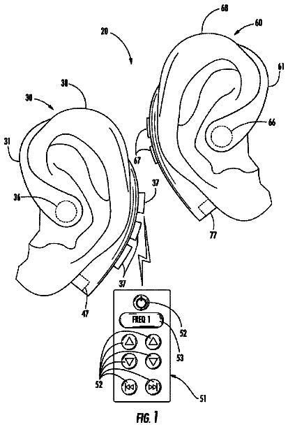
Particular embodiments described herein provide for an electronic device that includes a plurality of audio acquisition areas.
US 9,781,509 B2 · Assignee: CANON KABUSHIKI KAISHA · Inventors: Tawada; Noriaki
Sheet 1 of 10 from the published document. All sheets in the USPTO PDF
A signal processing apparatus acquires an audio signal of channels using a sound acquisition unit, at least a part of which is within a housing of the apparatus, and obtains an audio signal of channels from a microphone provided outside the housing. The apparatus processes an audio signal in accordance with a first propagation characteristic indicating propagation of sound associated with a direction of a sound source, in a case of processing an audio signal acquired by the sound acquisition unit and processes an audio signal in accordance with a second propagation characteristic different from the first propagation characteristic, in a case of processing an audio signal obtained by the microphone. The signal processing apparatus estimates a sound source direction using an audio signal processed by the first processing unit or an audio signal processed by the second processing unit.
Field of the Invention The present invention relates to signal processing apparatuses that perform audio processing, and signal processing methods. Description of the Related Art A technique of removing unnecessary noise from an audio signal is important for improving audibility to target sound included in the audio signal and increasing the recognition rate in speech recognition. Representative techniques of removing noise in an audio signal include a beamformer. This is for adding microphone signals of a plurality of channels acquired by a plurality of microphone elements after filtering each microphone signal, and obtaining a single output signal. The aforementioned filtering and addition processing corresponds to formation of a spatial beam pattern having a directivity, i.e., a direction-selectivity characteristic, using a plurality of microphone elements, and is therefore called the
1 of 10 drawing sheets so far from the published document, cropped to the drawing. Every sheet is in the USPTO PDF.
What the patent claimed, word for word. All of it is now free to use.
Field of the Invention
The present invention relates to signal processing apparatuses that perform audio processing, and signal processing methods.
Description of the Related Art
A technique of removing unnecessary noise from an audio signal is important for improving audibility to target sound included in the audio signal and increasing the recognition rate in speech recognition. Representative techniques of removing noise in an audio signal include a beamformer. This is for adding microphone signals of a plurality of channels acquired by a plurality of microphone elements after filtering each microphone signal, and obtaining a single output signal. The aforementioned filtering and addition processing corresponds to formation of a spatial beam pattern having a directivity, i.e., a direction-selectivity characteristic, using a plurality of microphone elements, and is therefore called the beamformer.
A portion at which sensitivity (gain) of a beam pattern reaches its peak is called a main lobe, and it is possible to emphasize target sound and simultaneously suppress noise existing in a direction different from the direction of the target sound by configuring the beamformer such that the main lobe is oriented to the direction of the target sound. However, the main lobe of a beam pattern forms a gentle curve having a wide width particularly in the case where the number of microphone elements is small. For this reason, even if such a main lobe of a beam pattern is oriented to the direction of the target sound, noise that is close to the target sound cannot be sufficiently removed.
In this regard, a noise removal method using not the main lobe but a null (dead angle), which is a portion at which the sensitivity of a beam pattern reaches its dip, has been proposed. That is to say, only noise can be sufficiently removed by orienting a sharp null to the direction of noise, without losing target sound whose direction is close to the noise direction. A beamformer that thus forms a null in a specific direction in a fixed manner is called a fixed beamformer. Here, if the direction to which the null is oriented is not accurate, noise removing performance significantly deteriorates, and accordingly estimation of the direction of a sound source is important.
In contrast with the fixed beamformer, a beamformer by which the null of a beam pattern is automatically formed is called an adaptive beamformer, and the adaptive beamformer can be used to estimate the sound source direction. Considering target sound and noise as directional sound sources whose power spatially concentrates on one point, a filter coefficient with which the null is automatically formed in the sound source direction can be obtained using the adaptive beamformer that is based on a rule that minimizes output power. Accordingly, in order to find the sound source direction, a beam pattern formed by a filter coefficient of the adaptive beamformer is calculated, and the null direction thereof need only be obtained. The beam pattern can be calculated by multiplying a filter coefficient by a transfer function called an array manifold vector between a sound source in each direction and each microphone element. For example, the angle of the direction in which the filter coefficient has a null that is a dip of the sensitivity is checked using array manifold vectors in −180° to 180° directions at 1° intervals.
Here, in sound source separation such as that performed using the beamformer, in general, an array manifold vector using a theoretical formula in a free field is often used, assuming that a microphone is arranged in a free field. Sound ideally propagates in a free field where there is no obstruction, and accordingly, for example, a difference in propagation delay time between microphone elements, i.e., a phase difference at each frequency between array manifold vector elements is geometrically obtained by a theoretical formula with a microphone interval as a parameter. In contrast, in the case where a microphone is arranged not in a free field but in the vicinity of a housing or therewithin, diffraction, blocking, scattering, or the like of sound occurs due to the housing, and accordingly the aforementioned phase difference diverges from the theoretical value in a free field. Furthermore, a difference in signal amplitude between microphone elements in each sound source direction is also affected by the housing in which the microphone elements are arranged.
Since the amplitude difference and the phase difference between the microphone elements significantly change due to the influence of the housing in which the microphones are arranged as mentioned above, the array manifold vector, which is a transfer function between a sound source in each direction and each microphone element, also changes due to the influence of the housing. If the array manifold vector used to calculate a beam pattern does not follow such a change, the sound source direction cannot be accurately estimated. Japanese Patent Laid-Open No. 2011-199474 (hereinafter, Document 1) describes estimation of an array manifold vector that contains the influence of a housing, using independent component analysis. Japanese Patent Laid-Open No. 2010-278918 (hereinafter, Document 2) describes sequentially obtaining microphone position coordinates that change in accordance with an open/close state of a housing movable portion and using the microphone position coordinates as parameters in sound source separation processing, in the case where a microphone is attached to the housing movable portion of a foldable mobile phone or the like.
However, there are cases where the accuracy of the sound source estimation cannot yet be maintained with the methods described in Documents 1 and 2. With the method in Document 1, for example, in the case of using a built-in microphone in a camcorder, it is conceivable that an array manifold vector which contains the influence of the housing of the camcorder can be estimated and used. However, in the case of switching the microphone used to obtain the audio signal from the built-in microphone to an external microphone, the external microphone is separate from the camcorder and is therefore not easily affected by the housing of the camcorder. That is to say, the array manifold vector significantly changes between the built-in microphone and the external microphone. In Document 1, selection of the array manifold vector while assuming such a case where the microphone is switched is not at all considered.
Regarding the method in Document 2, since the microphone position coordinates are parameters in the sound source separation processing, it is conceivable that a free field is assumed. However, in actual audio processing in a camcorder or the like, the array manifold vector used in the audio processing is affected by diffraction or the like caused by a housing. Furthermore, even if the microphone position coordinates do not change, if the shape of the housing changes due to interchange or zooming of a lens of the camcorder, for example, it is conceivable that the array manifold vector also changes accordingly. However, in Document 2, selection of the array manifold vector while taking such influence of a change of the housing shape on diffraction or the like into account is not considered.
According to an embodiment of the present invention, a signal processing apparatus and a signal processing method are provided that achieve highly accurate audio processing.
According to one aspect of the present invention, there is provided a signal processing apparatus that processes an audio signal comprising: a sound acquisition unit configured to acquire an audio signal of a plurality of channels, at least a part of the sound acquisition unit being within a housing of the signal processing apparatus; an obtaining unit configured to obtain an audio signal of a plurality of channels from a microphone provided outside the housing of the signal processing apparatus; a first processing unit configured to process an audio signal in accordance with a first propagation characteristic indicating propagation of sound associated with a direction of a sound source, in a case of processing an audio signal acquired by the sound acquisition unit; a second processing unit configured to process an audio signal in accordance with a second propagation characteristic different from the first propagation characteristic, in a case of processing an audio signal obtained by the obtaining unit; and an estimation unit configured to estimate a sound source direction using an audio signal processed by the first processing unit or an audio signal processed by the second processing unit.
According to another aspect of the present invention, there is provided a signal processing apparatus that processes an audio signal comprising: a sound acquisition unit configured to acquire an audio signal of a plurality of channels, at least a part of the sound acquisition unit being within a housing of the signal processing apparatus; a determination unit configured to determine a shape of the housing; a first obtaining unit configured to obtain a propagation characteristic of sound associated with a direction of a sound source in accordance with the shape of the housing determined by the determination unit; a processing unit configured to process an audio signal acquired by the sound acquisition unit in accordance with a propagation characteristic obtained by the first obtaining unit; and an estimation unit configured to estimate a sound source direction using an audio signal processed by the processing unit.
According to another aspect of the present invention, there is provided a signal processing method for processing an audio signal comprising: a sound acquiring step of acquiring an audio signal of a plurality of channels using a sound acquisition unit, at least a part of the sound acquiring unit being within a housing of the signal processing apparatus; an obtaining step of obtaining an audio signal of a plurality of channels from a microphone provided outside the housing of the signal processing apparatus; a first processing step of processing an audio signal in accordance with a first propagation characteristic indicating propagation of sound associated with a direction of a sound source, in a case of processing an audio signal acquired in the sound acquiring step; a second processing step of processing an audio signal in accordance with a second propagation characteristic different from the first propagation characteristic, in a case of processing an audio signal obtained in the obtaining step; and an estimation step of estimating a sound source direction using an audio signal processed in the first processing step or an audio signal processed in the second processing step.
According to another aspect of the present invention, there is provided a signal processing method for processing an audio signal comprising: a sound acquiring step of acquiring an audio signal of a plurality of channels using a sound acquisition unit, at least a part of the sound acquiring unit being within a housing of a signal processing apparatus; a determination step of determining a shape of the housing; an obtaining step of obtaining a propagation characteristic of sound associated with a direction of a sound source in accordance with the shape of the housing determined in the determination step; a processing step of processing an audio signal acquired in the sound acquiring step in accordance with a propagation characteristic obtained in the obtaining step; and an estimation step of estimating a sound source direction using an audio signal processed in the processing step.
Further features of the present invention will become apparent from the following description of exemplary embodiments with reference to the attached drawings.
FIG. 1 is a block diagram showing an exemplary configuration of a signal processing apparatus according to an embodiment.
FIGS. 2A and 2B are diagrams illustrating influence that a housing has on an array manifold vector.
FIGS. 3A to 3C are diagrams illustrating influence that selection of the array manifold vector has on beam patterns.
FIGS. 4A to 4E are diagrams illustrating influence that accuracy of estimation of a sound source direction has on noise removing performance.
FIG. 5 is a flowchart illustrating audio processing according to an embodiment.
FIG. 6 is a flowchart illustrating average beam pattern calculation processing according to an embodiment.
FIGS. 7A to 7E are diagrams illustrating external microphone interval estimation processing according to an embodiment.
FIG. 8 is a flowchart of the external microphone interval estimation processing according to an embodiment.
FIG. 9 is a flowchart of substitute array manifold vector selection processing according to an embodiment.
Hereinafter, an exemplary preferable embodiment of the present invention will be described in detail with reference to the attached drawings. Note that configurations and the like described in the following embodiment are merely examples, and the present invention is described in the embodiment and not limited to configurations shown in the drawings. Note that, in the drawings, an array manifold vector indicating a transfer function between a sound source in each direction and each microphone element will be abbreviated as an AMV.
First, divergence of a phase difference between microphone elements from a theoretical value thereof due to the influence of a housing will be described with reference to FIGS. 2A and 2B . Thin lines in FIG. 2A indicate, for respective frequencies, phase differences between microphone elements in respective sound source directions when using a camcorder that has two microphone elements as built-in microphones, the phase differences being measured by a traverse apparatus in an anechoic chamber. Here, the front 0°, which is a shooting direction of the camcorder, is in a direction of a perpendicular bisector of a line connecting the two built-in microphone elements. The frequency is displayed at every 187.5 Hz from 187.5 Hz to 1875 Hz, and the phase difference tends to be larger as the frequency is higher. On the other hand, smooth thick lines in FIG. 2A indicate theoretical values in a free field at each frequency using the interval between the aforementioned built-in microphones as a parameter. At each frequency, the phase difference is geometrically largest in the ±90° direction, which is the direction of the line connecting the two microphone elements. Here, comparing the theoretical value with the measured value of the phase difference at the same frequency, it is found that the measured value tends to be larger than the theoretical value in a free field due to the influence of diffraction or the like caused by the housing of the camcorder.
Similarly, thin lines in FIG. 2B indicate, for respective frequencies, measured values of amplitude difference between the microphone elements in respective sound source directions when using the aforementioned camcorder. Here, it is assumed that the amplitude difference is normalized by an amplitude sum, and is in the range from −1 to 1. As in the case of the phase difference, the amplitude difference tends to be larger as the frequency is higher in the vicinity of ±90°, which indicates a lateral direction. On the other hand, a thick line in FIG. 2B indicates theoretical values in a free field regarding which space attenuation based on the inverse-square law is taken into account, and it is found that almost no amplitude difference occurs with a microphone interval of several centimeters. As described above, the amplitude difference and the phase difference between the microphone elements are affected by the housing in which the microphones are arranged, and significantly change.
Next, the influence that selection of the array manifold vector has on a beam pattern will be specifically described. FIGS. 3A to 3C show the influence that selection of the array manifold vector used to calculate a beam pattern of the adaptive beamformer has on the beam pattern and sound source direction estimation. Here, beam patterns are obtained at respective frequencies, and thin lines in FIGS. 3A to 3C display, as a part of these beam patterns, beam patterns from 750 Hz to 7500 Hz at every 750 Hz. Thick lines in FIGS. 3A to 3C display average beam patterns, which are obtained by averaging the beam patterns at respective frequencies.
In FIG. 3A , a sound source is arranged in the −30° direction, an audio signal is obtained using microphones arranged in a free field to calculate a filter coefficient of the adaptive beamformer, and beam patterns thereof are calculated and displayed. Here, an array manifold vector generated by a theoretical formula in a free field with a microphone interval as a parameter is used. This is equivalent to selecting and using an array manifold vector corresponding to a state at the time of obtaining the audio signal with the microphones arranged in a free field. As a result, as indicated by the thick line in FIG. 3A , an average beam pattern in which a null is formed in the −30° direction, which is the sound source direction, is obtained, and the sound source direction can be accurately found from the null direction of the average beam pattern indicated by a vertical dotted line in FIG. 3A . Note that a beam pattern from −90° to 90° through 0° and a beam pattern from −90° to 90° through ±180° are symmetric.
On the other hand, in FIGS. 3B and 3C , a sound source is arranged in the −40° direction, the audio signal is obtained using the built-in microphones in the camcorder to calculate a filter coefficient of the adaptive beamformer, and beam patterns thereof are calculated and displayed. In FIG. 3B , an array manifold vector is used that is generated using a theoretical formula in a free field with the interval between these built-in microphones as a parameter. This situation means that an array manifold vector which is different from that corresponding to the state at the time of obtaining the audio signal affected by the housing of the camcorder is selected and used. As a result, for example, the average beam pattern only widely and shallowly recesses around −90° as indicated by the thick line in FIG. 3B , and it is difficult to say that the null is appropriately formed. For this reason, the sound source direction cannot be accurately estimated from the null direction of the average beam pattern.
In FIG. 3C , an array manifold vector measured in an anechoic chamber is used as a transfer function between the sound source in each direction and the built-in microphones in the camcorders. This means that an array manifold vector corresponding to the state at the time of obtaining the audio signal affected by the housing of the camcorder is selected and used. As a result, as indicated by the thick line in FIG. 3C , an average beam pattern is obtained in which the null is formed in the −40° direction, which is the sound source direction, and the sound source direction can be accurately found from the null direction of the average beam pattern indicated by a vertical dotted line in FIG. 3C . Note that if the shape of the housing is roughly symmetric with respect to the shooting direction as in the case of a camcorder, the beam pattern from −90° to 90° through 0° and the beam pattern from −90° to 90° through ±180° are also roughly symmetric.
For these reasons, it can be understood that, in the calculation of a beam pattern of a beamformer, selecting and using an array manifold vector corresponding to the state at the time of obtaining the audio signal is important for estimating the sound source direction from the null of the beam pattern. Here, the state at the time of obtaining the audio signal is affected by the shape of the housing or the like.
FIGS. 4A to 4E are diagrams further showing the influence that the selection of the array manifold vector and the accuracy of the estimation of the sound source direction have on the noise removing performance. For example, consider the case where, when filming a piano recital using a camcorder, sound of coughing of an audience, such as the sound shown in FIG. 4B , comes from the −40° direction in addition to sound of the piano in the front direction, such as the sound shown in FIG. 4A . In this case, each channel of the audio signal obtained by the built-in microphones in the camcorder indicates a mixture of the sound of the piano and the sound of the coughing, as shown in FIG. 4C . Now, consider removal of the sound of the coughing, which is noise, from this audio signal.
The sound of the coughing is dominant in a section enclosed by a thick line 401 in FIGS. 4A to 4E . Therefore, if an adaptive beamformer is configured from the audio signal at this time, a filter coefficient with which the null is automatically formed in the direction of the coughing is obtained. Accordingly, the direction of the coughing can be estimated from the null direction by calculating a beam pattern formed by this filter coefficient. However, as mentioned above, if an array manifold vector generated by a theoretical formula in a free field is used even though the audio signal is obtained using the built-in microphones in the camcorder, the null is not appropriately formed as shown in FIG. 3B , for example. On the other hand, if an array manifold vector that contains the influence of the housing of the camcorder is used, the direction of the coughing can be accurately estimated to be −40° from the null direction of the average beam pattern as shown in FIG. 3C , for example.
FIG. 4D shows a result of deeming −90° indicated by a vertical dotted line in FIG. 3B to be a provisional null direction and orienting the null to this direction with the fixed beamformer. However, the direction (−90°) to which the null is oriented is shifted from the direction (−40°) of the coughing, and therefore the sound of the coughing has not been effectively removed. On the other hand, FIG. 4E shows a result of orienting the null to −40° indicated by the vertical dotted line in FIG. 3C with the fixed beamformer. Since the direction to which the null is oriented coincides with the direction of the coughing, the sound of the coughing has been effectively removed.
As described above, the accuracy of the estimation of the sound source direction significantly affects the noise removing performance. Furthermore, in addition to the sound source direction estimation, calculation of the filter coefficient of the aforementioned fixed beamformer requires the array manifold vector in the direction to which the null is oriented. For this reason, the appropriateness of the selection of the array manifold vector also affects the calculation of the filter coefficient of the fixed beamformer. Accordingly, in audio processing such as noise removal, it is important to select an array manifold vector appropriate for the environment at the time of acquiring sound using microphone elements, such as the shape of a housing. In view of the above, the present embodiment will disclose a signal processing apparatus capable of selecting and using an array manifold vector corresponding to the state at the time of obtaining the audio signal which significantly changes due to the influence of a housing in audio processing such as noise removal.
FIG. 1 is a block diagram showing an exemplary configuration of a video camera (camcorder) according to the embodiment. A signal processing apparatus 100 includes a system control unit 101 that governs all constituent elements, a storage unit 102 that stores various data, and a signal analyzing unit 103 that performs signal analysis processing.
The video camera includes a built-in microphone 111 and an audio signal input unit 112 as elements for achieving a function of a sound acquisition system. Any external microphone 119 can also be connected to the signal processing apparatus 100 . In the present embodiment, the built-in microphone 111 and the external microphone 119 are each constituted by a 2ch stereo microphone in which two microphone elements are arranged at an interval. Note that the number of microphone elements need only be more than one, and may also be three or more. That is to say, the present invention is not limited to the case where the number of microphone elements is two.
The audio signal input unit 112 detects connection of the external microphone 119 , and if the external microphone 119 is connected, the audio signal input unit 112 inputs the audio signal not from the built-in microphone 111 but from the external microphone 119 . The audio signal input unit 112 also performs amplification and AD conversion on an analog audio signal from each microphone element in the built-in microphone 111 or the external microphone 119 , and generates a 2ch microphone signal, which is a digital audio signal, at a cycle corresponding to a predetermined audio sampling rate.
The video camera includes a lens unit 120 and a video signal input unit 124 as elements for achieving a function of an image capturing system. The lens unit 120 further includes an optical lens 121 , a lens control unit 122 , and an in-lens storage unit 123 . The lens unit 120 performs photoelectric conversion on light entering the optical lens 121 , and generates an analog video signal. The video signal input unit 124 performs AD conversion and gain adjustment on an analog video signal from the lens unit 120 , and generates a digital video signal at a cycle corresponding to a predetermined video frame rate. The lens control unit 122 communicates with the system control unit 101 to perform control for driving the optical lens 121 and exchange information regarding the lens unit 120 . The in-lens storage unit 123 stores information regarding the lens unit 120 . In the present embodiment, the lens unit 120 is constituted by an interchangeable lens that is interchangeable and whose lens housing extends and contracts in accordance with a zoom ratio. The video camera in the present embodiment also includes an input/output UI unit 131 as an element for accepting a user operation and presenting an operation menu, a video signal, and the like to a user. The input/output UI unit 131 is constituted by a touch panel, for example.
A detailed description will be given below of audio signal processing performed by the video camera (signal processing apparatus 100 ) in the present embodiment having the above-described configuration. Initially, prior to the shooting by the signal processing apparatus 100 , various array manifold vectors to be used in audio processing at the time of the shooting are obtained.
Upon the external microphone 119 being connected when shooting is not performed, the connection is detected by the audio signal input unit 112 . This detection is communicated from the audio signal input unit 112 to the system control unit 101 . Next, the input/output UI unit 131 prompts the user to input an external microphone interval, which is an interval between the microphone elements in the external microphone 119 , in accordance with an instruction from the system control unit 101 . The value input in millimeters, for example, by the user is set as the external microphone interval of the external microphone 119 and stored in the storage unit 102 . If the microphone interval is known, an array manifold vector can be generated by a theoretical formula in a free field. If the user does not know the external microphone interval, it should be noted that the external microphone interval may be left unset.
The signal processing apparatus 100 also stores, in the storage unit 102 , a transfer function, in which the way sound propagates within the housing is considered, for a sound source in each direction of each microphone element in the built-in microphone 111 . The signal processing apparatus 100 may obtain an array manifold vector, in which the way sound propagates within the housing is considered, of each microphone element in the built-in microphone 111 from the outside by means of communication.
For example, upon the lens unit 120 being attached through interchange of the lens when shooting is not performed, this attachment is detected by the system control unit 101 . Next, the system control unit 101 communicates with the lens control unit 122 in the lens unit 120 and identifies the type of the currently attached lens unit 120 . Furthermore, the system control unit 101 obtains, via the lens control unit 122 , an array manifold vector for the signal processing apparatus 100 from among a plurality of array manifold vectors stored in the in-lens storage unit 123 , and saves the obtained array manifold vector in the storage unit 102 . The array manifold vector for the signal processing apparatus 100 is an array manifold vector in the case where the audio signal is obtained by the built-in microphone 111 in the signal processing apparatus 100 in a state where the lens unit 120 is attached to the signal processing apparatus 100 . Note that the plurality of array manifold vectors are stored in the in-lens storage unit 123 in order to deal with a plurality of types of video cameras having different housing shapes.
In general, there are various types of interchangeable lenses having different focal lengths, f-numbers, and the like, and the shape of the lens housing is different for each type. For this reason, the lens unit 120 being attached to the signal processing apparatus 100 means a change of the housing shape of the signal processing apparatus 100 for each type of the lens unit 120 , and it is therefore conceivable that the array manifold vector also changes for each type of the lens unit 120 . Furthermore, in the case where the lens is a zoom lens, the shape of the lens housing extends and contracts in accordance with the zoom ratio. This means a change of the housing shape of the video camera (signal processing apparatus 100 ) in accordance with the zoom ratio, and it is therefore conceivable that the array manifold vector also changes in accordance with the zoom ratio of the lens unit 120 . Accordingly, if the lens unit 120 is a zoom lens, the system control unit 101 obtains the array manifold vector for each zoom ratio and saves the obtained array manifold vector in the storage unit 102 .
Thus, various array manifold vectors obtained from the lens unit 120 are saved in the storage unit 102 in association with the type of the interchangeable lens (type of the lens unit 120 ) and the zoom ratio thereof. Note that array manifold vectors corresponding to a lens attached to the signal processing apparatus 100 by default, a representative interchangeable lens that may possibly be attached to the signal processing apparatus 100 , a state where a lens is not attached, and the like may be stored in advance in the storage unit 102 .
Note that the array manifold vector which contains the influence of the housing of the signal processing apparatus 100 can be measured using the built-in microphone 111 for each type and zoom ratio of the lens unit 120 by means of a traverse apparatus in an anechoic chamber. Alternatively, an array manifold vector may be generated based on CAD data by simulation taking the wave nature into account, such as a finite-element method or a boundary element method.
Although the array manifold vector, which is a transfer function for each direction, is data of a frequency region, it should be noted that the array manifold vector may be stored in the form of an impulse response for each direction to serve as the origin of the array manifold vector, in the in-lens storage unit 123 in the lens unit 120 . When taking the impulse response for each direction into the storage unit 102 , Fourier transformation may be performed by the signal analyzing unit 103 in accordance with a frequency resolution in the audio processing performed by the signal processing apparatus 100 , and the obtained array manifold vector may be saved in the storage unit 102 .
Next, a shooting operation performed by the signal processing apparatus 100 will be described. A video signal taken by the image capturing system is projected on a screen of the input/output UI unit 131 in real time. At this time, a designated value of the zoom ratio is communicated to the system control unit 101 by moving a tab of a slider bar on the screen indicating the zoom ratio. The lens control unit 122 then performs control for driving the optical lens 121 in accordance with an instruction from the system control unit 101 , and performs optical zoom processing in accordance with the designated zoom ratio.
When in a situation in which the user wants to start shooting, the user touches and selects “REC” in a menu displayed on the input/output UI unit 131 . The signal processing apparatus 100 starts, in accordance with this selection, to record the video signal taken by the image capturing system and the audio signal taken by the sound acquisition system, in the storage unit 102 . A 2ch microphone signal, which is the audio signal obtained by the sound acquisition system, is sequentially recorded in the storage unit 102 , and sound source direction estimation processing and noise removal processing, which are the audio processing in the present embodiment, are performed in accordance with a flowchart in FIG. 5 . Note that the description will be given, assuming an audio sampling rate of 48 kHz.
A signal sampling unit with which a microphone signal is filtered in the beamformer will be called a time block, and the length of the time block is a length of 1024 samples (approx. 21 ms) in the present embodiment. A microphone signal is filtered within a time block loop while shifting a signal sampling range by 512 samples (approx. 11 ms), which is half the aforementioned time block length. That is to say, a first sample to a 1024th sample of a microphone signal are filtered in the first time block, and a 513th sample to a 1536th sample are filtered in the second time block. It is assumed that the flowchart in FIG. 5 shows processing in one time block within a time block loop.
In step S 501 , the system control unit 101 communicates with the audio signal input unit 112 and checks whether the external microphone 119 is connected. If the external microphone 119 is connected, i.e., if the audio signal is obtained by the external microphone 119 , the processing proceeds to step S 502 . In step S 502 , the system control unit 101 checks whether the external microphone interval of the external microphone 119 is set, and if the external microphone interval is set, the processing proceeds to step S 503 .
In step S 503 , the signal analyzing unit 103 generates an array manifold vector with the set external microphone interval as a parameter. The generated array manifold vector is selected as an array manifold vector to be used in processing of the audio signal in a time block that is currently obtained by the external microphone 119 . Since the external microphone 119 is separate from the signal processing apparatus 100 , it is conceivable that the external microphone 119 is not easily affected by the housing of the signal processing apparatus 100 . Accordingly, an array manifold vector a(f, θ) is generated by a theoretical formula in a free field expressed by Equation
below and the external microphone interval, and is selected for later audio processing. a ( f , θ)= exp (− j 2 f τ(θ, d ))
Here, j denotes an imaginary unit, and f denotes a frequency. Also consider a unit sphere whose center is the center between the two microphone elements in the external microphone 119 . Then, a delay time of propagation from a point at an azimuth θ on the unit sphere to each microphone element is τ.sub.i(θ, d) (i=1, 2), which is a function of the azimuth θ and the external microphone interval d, and this function is collectively put as vector τ(θ)=[τ.sub.1(θ) τ.sub.2(θ)].sup.T. Here, a superscript “T” denotes transposition. Note that it is assumed that the front (θ=0°), which is the shooting direction of the signal processing apparatus 100 , is in the direction of a perpendicular bisector of a line connecting the two external microphone elements.
On the other hand, if, in step S 501 , the external microphone 119 is not connected, i.e., if the audio signal is obtained by the built-in microphone 111 , the processing proceeds to step S 504 . In step S 504 , the system control unit 101 communicates with the lens control unit 122 in the lens unit 120 , and obtains the type of the lens unit 120 and the current zoom ratio. In step S 505 , the system control unit 101 checks whether the storage unit 102 stores the array manifold vector corresponding to the type of the lens unit 120 obtained in step S 504 , and if so, the processing proceeds to step S 506 .
In step S 506 , the signal analyzing unit 103 selects an array manifold vector to be used in the processing of the audio signal in the current time block that is obtained by the built-in microphone 111 . That is to say, an array manifold vector a(f, θ) corresponding to the type and the current zoom ratio of the lens unit 120 that are obtained in step S 504 is selected. Here again, it is assumed that the front) (θ=0°), which is the shooting direction of the signal processing apparatus 100 , is in the direction of a perpendicular bisector of a line connecting the two built-in microphone elements.
Note that, regarding the zoom ratio, the array manifold vector that perfectly coincides with the current zoom ratio does not always exist. Accordingly, in the present embodiment, an array manifold vector corresponding to a zoom ratio that is closest to the current zoom ratio is to be selected. Alternatively, an array manifold vector corresponding to the current zoom ratio (e.g., 2.5 times) may be generated and selected by interpolating array manifold vectors corresponding to a plurality of zoom ratios (e.g., 2 times and 3 times) on the amplitude and the phase. If the lens is being interchanged and the lens unit 120 is not attached to the signal processing apparatus 100 , it should be noted that the array manifold vector corresponding to the state where the lens is not attached may be selected.
After finishing the processing in step S 503 or S 506 as above, the processing proceeds to step S 507 . The processing in step S 507 and subsequent steps are performed mainly by the signal analyzing unit 103 . In step S 507 , the signal analyzing unit 103 performs average beam pattern calculation processing. The average beam pattern calculation processing will now be described in detail with reference to a flowchart in FIG. 6 .
In step S 601 , the signal analyzing unit 103 performs Fourier transformation on the 2ch microphone signal in the current time block and obtains a Fourier coefficient, which is a complex number. At this time, a time resolution and a frequency resolution in the Fourier transformation are determined by the time block length. A spatial correlation matrix is calculated in next step S 602 , and since the calculation of a spatial correlation matrix, which is a statistic, requires average processing, a unit called a time frame is introduced with the current time block as a reference.
The description continues in the full USPTO document.
About 6,610 words. The USPTO PDF has it with every drawing.
Fees are due 3.5, 7.5 and 11.5 years after grant. This patent expired on October 3, 2025, so the fee marked "not paid" was the one that went unpaid.
SIGNAL PROCESSING APPARATUS AND SIGNAL PROCESSING METHOD
Filed Jul 2015 · published Feb 2016Signal processing apparatus and signal processing method
Filed Jul 2015 · granted Oct 2017Earlier publications, parents and continuations. None of them can still be enforced, or this patent would not be listed.
Prior art cited by the examiner or applicant. Useful when you check your own idea for novelty.
Everything on this page comes from the documents linked above.