Background
The present invention relates to an image processing system, an information processing device, an information storage device, an image processing method, and the like.
In recent years, a technique that generates a panoramic image using a digital camera has been developed. A panoramic image is normally generated by stitching a plurality of still images captured while moving an imaging section in one direction.
JP-A-2010-28764 discloses a technique that generates a panoramic image based on slits extracted from consecutively captured images to increase the consecutive shooting speed and the slit synthesis speed while eliminating discontinuity during image synthesis.
Japanese Patent No. 3466493 discloses a method that generates a panoramic image that is mainly used for navigation applications. The method disclosed in Japanese Patent No. 3466493 extracts slits from consecutive images captured using an on-board stationary camera to synthesize a panoramic image. The method disclosed in Japanese Patent No. 3466493 makes it unnecessary to employ an image synthesis process based on a feature point that increases the processing load, and can generate a panoramic image at a higher speed.
According to the panoramic synthesis method disclosed in JP-A-2010-28764 or Japanese Patent No. 3466493, a panoramic image can be synthesized taking account of motion parallax by stitching trimmed rectangular areas (slits).
Summary
According to one aspect of the invention, there is provided an image processing system comprising:
an image acquisition section that consecutively acquires still images;
a direction determination section that determines a camera moving direction, the camera moving direction being a moving direction of an imaging section during capture;
a slit image generation section that generates slit images based on the consecutively acquired still images; and
a panoramic image generation section that performs a synthesis process of the slit images to generate a panoramic image,
the direction determination section determining whether the camera moving direction is a first camera moving direction or a second camera moving direction that differs from the first camera moving direction when the imaging section is moved during capture, and
the panoramic image generation section determining a synthesis position of a slit image among the slit images based on the camera moving direction when the consecutively acquired still images were captured, and performing the synthesis process of the slit image to generate the panoramic image.
According to another aspect of the invention, there is provided an information processing device comprising:
a direction determination section that determines a camera moving direction, the camera moving direction being a moving direction of an imaging section during capture;
a panoramic image generation section that performs a synthesis process of slit images generated based on still images consecutively acquired by an image acquisition section to generate a panoramic image; and
a storage section that stores the slit images and the generated panoramic image,
the direction determination section determining whether the camera moving direction is a first camera moving direction or a second camera moving direction that differs from the first camera moving direction when the imaging section is moved during capture, and
the panoramic image generation section determining a synthesis position of a slit image among the slit images generated based on the consecutively acquired still images, based on the camera moving direction when the consecutively acquired still images were captured, and performing the synthesis process of the slit image to generate the panoramic image.
According to another aspect of the invention, there is provided a computer-readable storage device with an executable program stored thereon, wherein the program instructs a computer to perform steps of:
determining a camera moving direction, the camera moving direction being a moving direction of an imaging section during capture;
performing a synthesis process of slit images generated based on consecutively acquired still images to generate a panoramic image;
determining whether the camera moving direction is a first camera moving direction or a second camera moving direction that differs from the first camera moving direction when the imaging section is moved during capture;
determining a synthesis position of a slit image among the slit images generated based on the consecutively acquired still images based on the camera moving direction when the consecutively acquired still images were captured; and
performing the synthesis process of the slit image to generate the panoramic image.
According to another aspect of the invention, there is provided an image processing method comprising:
consecutively acquiring still images;
determining whether a camera moving direction is a first camera moving direction or a second camera moving direction that differs from the first camera moving direction when an imaging section is moved during capture, the camera moving direction being a moving direction of the imaging section during capture;
generating slit images based on the consecutively acquired still images;
determining a synthesis position of a slit image among the slit images based on the camera moving direction when the consecutively acquired still images were captured; and
performing a synthesis process of the slit image to generate a panoramic image.
Brief description of the drawings
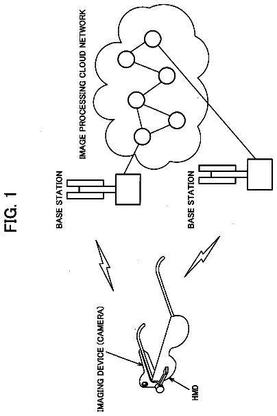
FIG. 1 illustrates a system configuration example according to one embodiment of the invention.
FIG. 2 illustrates a detailed system configuration example according to one embodiment of the invention.
FIGS. 3A to 3C are views illustrating a difference in perspective due to motion parallax.
FIGS. 4A and 4B are views illustrating a slit image.
FIG. 5 is a view illustrating a technique that generates a panoramic image while moving an imaging section in a plurality of directions.
FIG. 6 is a view illustrating an overlapping area.
FIGS. 7A to 7C are views illustrating a positioning slit.
FIG. 8 is a view illustrating a method that synthesizes a slit image using a positioning slit.
FIGS. 9A and 9B are views illustrating a method that extracts a plurality of positioning slits from a single still image.
FIG. 10 is a view illustrating a method that changes a positioning slit extraction position.
FIGS. 11A and 11B illustrate examples of a method that selects a positioning slit.
FIGS. 12A and 12B illustrate further examples of a method that selects a positioning slit.
FIGS. 13A to 13C are views illustrating a method that limits an overlapping area search range.
FIG. 14 is a view illustrating a method that increases an image acquisition rate when a camera moving speed has increased.
FIG. 15 is a view illustrating a method that increases a slit image width when a camera moving speed has increased.
FIG. 16 is a flowchart illustrating the flow of a process according to one embodiment of the invention.
FIG. 17 is a flowchart illustrating the flow of a panoramic synthesis process according to one embodiment of the invention.
FIG. 18 illustrates another system configuration example according to one embodiment of the invention.
Description of exemplary embodiments
JP-A-2010-28764 and Japanese Patent No. 3466493 disclose a technique that generates a panoramic image by moving the imaging section in one direction, but do not disclose a technique that generates a panoramic image by moving the imaging section in a plurality of directions.
Several embodiments of the invention may provide an image processing system, an information processing device, an information storage device, an image processing method, and the like that can generate a panoramic image based on a slit image when the imaging section is moved in a plurality of directions during capture.
Several embodiments of the invention may provide an image processing system, an information processing device, an information storage device, an image processing method, and the like that can generate a panoramic image based on a slit image and a positioning slit when the imaging section is moved in a plurality of directions during capture.
According to the above configuration, when the imaging section is moved in a plurality of camera moving directions during capture, still images used to generate the slit images are consecutively acquired, and the current camera moving direction is determined. The slit image is generated based on a still image among the consecutively acquired still images. The synthesis position of the slit image is determined based on the camera moving direction, and the synthesis process is then performed. It is possible to generate a panoramic image of which the angle of view is wider in a plurality of directions than that of a panoramic image generated by moving the imaging section in one camera moving direction while reducing a difference in perspective due to motion parallax by utilizing the slit images.
The image processing system may further comprise:
a positioning slit generation section that generates a positioning slit based on a still image among the consecutively acquired still images,
the panoramic image generation section may determine the synthesis position of the slit image based on the camera moving direction when the consecutively acquired still images were captured, and the positioning slit, and may perform the synthesis process of the slit image to generate the panoramic image.
According to the above configuration, since a problem does not occur even when one slit image has an overlapping area with a plurality of slit images, the overlapping area can be relatively easily specified, for example.
In the image processing system,
the positioning slit generation section may generate the positioning slit so that a long side of the slit image is orthogonal to a long side of the positioning slit.
According to the above configuration, the overlapping area can be specified so that the short side of the slit image coincides with the long side of the positioning slit, for example.
In the image processing system,
the positioning slit generation section may set a first area and a second area based on a straight line that passes through a center of the still image, may generate a first positioning slit from the first area, and may generate a second positioning slit from the second area.
The above configuration makes it possible to selectively use the first positioning slit or the second positioning slit when specifying the overlapping area of the slit images, for example. Specifically, it is possible to select the positioning slit corresponding to the camera moving direction, and determine the overlapping area even when the imaging section is moved in an arbitrary direction, for example.
In the image processing system,
the positioning slit generation section may change an extraction position of the positioning slit within the still image based on motion information about the imaging section acquired from a motion information acquisition section, and may generate the positioning slit.
The above configuration makes it possible to extract the positioning slit from the same position as that of the previously used positioning slit when the position of the imaging section has changed to a large extent, and efficiently perform the search process that searches the overlapping area of the synthesis target image and the positioning slit, for example.
In the image processing system,
the panoramic image generation section may shift the synthesis position in a direction perpendicular to the first camera moving direction when it has been determined that the camera moving direction is the second camera moving direction, and may perform the synthesis process so that part of the positioning slit overlaps part of the slit image to generate the panoramic image.
The above configuration makes it possible to generate a panoramic image that covers a wide range of the imaging area in the vertical direction and the horizontal direction when the imaging section was moved along a zigzag path, for example.
In the image processing system,
the direction determination section may determine the camera moving direction when the imaging section is moved in the first camera moving direction, moved in a third camera moving direction that differs from the first camera moving direction and the second camera moving direction, and then moved in the second camera moving direction during capture, and
the panoramic image generation section may use the positioning slit generated based on the still image acquired when the camera moving direction is the first camera moving direction for the synthesis process when the positioning slit was generated from an area of the still image assigned in the third camera moving direction relative to a center of the still image, and may use the positioning slit generated based on the still image acquired when the camera moving direction is the second camera moving direction for the synthesis process when the positioning slit was generated from an area of the still image assigned in a direction opposite to the third camera moving direction relative to the center of the still image.
The above configuration makes it possible to specify the positioning slit by which the slit image can be synthesized so that the angle of view of the synthesized image is sufficiently larger than the angle of view of the original slit image.
In the image processing system,
the panoramic image generation section may limit a search range for a position of an overlapping area of the positioning slit and the slit image based on motion information about the imaging section acquired from a motion information acquisition section, and may perform the synthesis process.
The above configuration makes it possible to limit the overlapping area search range to an area around the position estimated based on the motion information after the imaging section has been moved, and perform the process that specifies the overlapping area at high speed (i.e., reduce the load of the process that specifies the overlapping area), for example.
In the image processing system,
the panoramic image generation section may limit the search range for the position of the overlapping area of the positioning slit and the slit image based on a horizontal component or a vertical component of the motion information about the imaging section acquired from the motion information acquisition section, and may perform the synthesis process.
According to the above configuration, the search range can be limited relative to the positioning slit.
In the image processing system,
the slit image generation section may generate the slit images that have a long side along a direction corresponding to a horizontal component or a vertical component, whichever is smaller in absolute value, of a vector that indicates the camera moving direction.
The above configuration makes it possible to generate a slit image that does not include an area of the still image in the camera moving direction and an area of the still image in the direction opposite to the camera moving direction, and suppress the effects of a difference in perspective due to motion parallax, for example.
In the image processing system,
the slit image generation section may generate the slit images that have the long side along the direction corresponding to the horizontal component or the vertical component, whichever is smaller in absolute value, of the vector that indicates the camera moving direction, and include a center of a still image among the consecutively acquired still images.
The above configuration makes it possible to generate a slit image that does not include an area of the still image in the camera moving direction and an area of the still image in the direction opposite to the camera moving direction, and includes the center of the still image, and further suppress the effects of a difference in perspective due to motion parallax, for example.
In the image processing system,
the panoramic image generation section may perform the synthesis process of the slit image so that the slit image has an overlapping area with the slit image that was used for a preceding synthesis process in the camera moving direction when the slit image used for the preceding synthesis process was captured to generate the panoramic image.
The above configuration makes it possible to perform the synthesis process while making the generated slit images overlap in the camera motion direction.
In the image processing system,
the direction determination section may determine whether the camera moving direction is the first camera moving direction, the second camera moving direction, or a third camera moving direction that differs from the first camera moving direction and the second camera moving direction when the imaging section is moved during capture.
The above configuration makes it possible to generate the panoramic image by moving the imaging section along a zigzag path.
In the image processing system,
the panoramic image generation section may perform a process that synthesizes the slit images in the first camera moving direction and a process that synthesizes the slit images in the second camera moving direction in parallel.
According to the above configuration, since the slit images can be synthesized in the second camera moving direction even when the slit images have not been completely synthesized in the first camera moving direction, it is possible to prevent a situation in which the process that synthesizes the slit images in the first camera moving direction becomes a bottleneck, and the panoramic image generation process can be performed at high speed, for example.
In the image processing system,
the panoramic image generation section may perform the synthesis process of the slit image based on a first error tolerance, and may then perform the synthesis process of the slit image based on a second error tolerance that is lower than the first error tolerance.
According to the above configuration, the overlapping area of the slit image can be specified based on the first error tolerance, and the accuracy of the synthesis position of the slit image can be improved based on the second error tolerance, for example.
In the image processing system,
the image acquisition section may stop acquisition of the still images when motion information about the imaging section has been acquired from motion information acquisition section, and it has been determined that an overlapping area of consecutive slit images among the slit images has not occurred in the synthesis process of the slit image based on the motion information.
The above configuration makes it possible to prevent a situation in which the still images are consecutively acquired although consecutive slit images do not have an overlapping area, and a panoramic image cannot be generated, for example.
In the image processing system,
the image acquisition section may increase an image acquisition rate so that an overlapping area of consecutive slit images among the slit images is larger than a given threshold value during the synthesis process of the slit image when it has been determined that a camera moving speed has increased based on motion information about the imaging section acquired from a motion information acquisition section, the camera moving speed being a moving speed of the imaging section.
The above configuration makes it possible to obtain the slit images having an overlapping area necessary for synthesizing the panoramic image.
In the image processing system,
the slit image generation section may increase a width of the slit image so that an overlapping area of consecutive slit images among the slit images is larger than a given threshold value during the synthesis process of the slit image when it has been determined that a camera moving speed has increased based on motion information about the imaging section acquired from a motion information acquisition section, the camera moving speed being a moving speed of the imaging section.
The above configuration makes it possible to obtain the slit images having an overlapping area necessary for synthesizing the panoramic image even when the image acquisition rate (sampling rate) cannot be increased due to limitations to the hardware or the network, for example.
In the image processing system,
the image acquisition section may control a shutter release timing of the imaging section to consecutively acquire the still images.
The above configuration makes it possible to cause the number of still images captured by the imaging section to coincide with the number of still images acquired by the image acquisition section, and cause the image acquisition section to acquire the desired number of still images while preventing a situation in which the imaging section captures unnecessary still images, for example.
In the information processing device,
the storage section may store a positioning slit generated by a positioning slit generation section based on a still image among the consecutively acquired still images, and
the panoramic image generation section may determine the synthesis position of the slit image based on the camera moving direction when the consecutively acquired still images were captured, and the positioning slit, and may perform the synthesis process of the slit image to generate the panoramic image.
In the information processing device,
the panoramic image generation section may shift the synthesis position in a direction perpendicular to the first camera moving direction when it has been determined that the camera moving direction is the second camera moving direction, and may perform the synthesis process so that part of the positioning slit overlaps part of the slit image to generate the panoramic image.
In the information processing device,
the slit images may have a long side along a direction corresponding to a horizontal component or a vertical component, whichever is smaller in absolute value, of a vector that indicates the camera moving direction, and may include a center of a still image among the consecutively acquired still images.
In the information processing device,
the panoramic image generation section may perform the synthesis process of the slit image so that the slit image has an overlapping area with the slit image that was used for a preceding synthesis process in the camera moving direction when the slit image used for the preceding synthesis process was captured to generate the panoramic image.
Exemplary embodiments of the invention are described below. An outline and a system configuration example will be described first. A specific embodiment and a method will then be described. The flow of a process will then be described using a flowchart. Note that the following exemplary embodiments do not in any way limit the scope of the invention laid out in the claims. Note also that all of the elements described below in connection with the following exemplary embodiments should not necessarily be taken as essential elements of the invention.
1. Outline
In recent years, a technique that generates a panoramic image using a digital camera has been developed. A panoramic image is normally generated by stitching a plurality of still images captured while moving an imaging section in one direction.
When an image is captured while moving the imaging section, a difference in perspective due to motion parallax may occur in the captured still images (see FIGS. 3A to 3C ). In this case, the still images may not be successfully synthesized due to the difference in perspective, and it may be difficult to generate a panoramic image. In order to reduce the effects of a difference in perspective, a technique that extracts a slit image from a still image, and generates a panoramic image using the slit image has been developed. For example, JP-A-2010-28764 and Japanese Patent No. 3466493 disclose such a technique.
JP-A-2010-28764 discloses a technique that generates a panoramic image based on slits extracted from consecutively captured images to increase the consecutive camera moving speed and the slit synthesis speed while eliminating discontinuity during image synthesis.
Japanese Patent No. 3466493 discloses a method that generates a panoramic image that is mainly used for navigation applications. The method disclosed in Japanese Patent No. 3466493 extracts slits from consecutive images captured using an on-board stationary camera to synthesize a panoramic image. The method disclosed in Japanese Patent No. 3466493 makes it unnecessary to employ an image synthesis process based on a feature point that increases the processing load, and can generate a panoramic image at a higher speed.
According to the panoramic synthesis method disclosed in JP-A-2010-28764 or Japanese Patent No. 3466493, a panoramic image can be synthesized taking account of motion parallax by stitching trimmed rectangular areas (slits).
However, JP-A-2010-28764 and Japanese Patent No. 3466493 disclose a technique that generates a panoramic image by moving the imaging section in one direction, but do not disclose a technique that generates a panoramic image by moving the imaging section in a plurality of directions.
A technique that generates a panoramic image by moving the imaging section in one direction has a problem in that the angle of view of the panoramic image can be adjusted only in the moving direction of the imaging section. For example, the angle of view of the panoramic image cannot be increased in the direction perpendicular to the moving direction of the imaging section.
If still images captured while moving the imaging section in a plurality of directions can be provided by moving the imaging section in a plurality of directions during capture, it is possible to generate a panoramic image of which the angle of view is increased in a plurality of directions.
According to several embodiments of the invention, when the imaging section is moved in a plurality of camera moving directions during capture, still images are consecutively acquired, slit images are extracted from the consecutively acquired still images, and a panoramic image is generated based on the extracted slit images.
Since the overlapping area of the slit images is smaller than the overlapping area of the still images, it may be difficult to specify the overlapping area of the slit images. According to several embodiments of the invention, a positioning slit is extracted from the still image in addition to the slit image, and a panoramic image is generated based on the slit image and the positioning slit in order to deal with the above problem.
2. System Configuration Example
FIG. 1 illustrates a configuration example of an image processing system according to one embodiment of the invention. In one embodiment of the invention, the image processing system is a server on an image processing cloud network. The image processing system may include a head mounted display (HMD), an imaging device (camera), and the like in addition to the image processing cloud network. The image processing system may be an information processing device included in an HMD or the like.
In one embodiment of the invention, the user captures the object using an imaging device included in (provided to) an HMD while shaking his/her head to generate still images (or slit images or a movie), which are transmitted to the server on the image processing cloud network through a base station via wireless communication. The server generates a panoramic image, and the user views the panoramic image on the HMD.
Note that the embodiments of the invention are for illustrative purposes only, and the image processing system is not limited to the configuration illustrated in FIG. 1 . For example, various modifications may be made, such as omitting some of the elements illustrated in FIG. 1 , or adding other elements. Note that the still image or the like need not necessarily be transmitted to the image processing system via wireless communication, but may be transmitted to the image processing system via cable communication. When the image processing system is an information processing device that is included in the HMD, the image processing system need not necessarily receive the still image or the like through a network, but may acquire the still image or the like through an internal bus or the like. The imaging device need not necessarily be integrated with the HMD, but may be a handheld camera or the like. The output device (e.g., HMD) need not necessarily be provided.
FIG. 2 illustrates a detailed configuration example of the image processing system according to one embodiment of the invention. An image processing system 200 illustrated in FIG. 2 includes a direction determination section 210 , a panoramic image generation section 220 , a storage section 230 , an I/F section 240 , a slit image generation section 250 , a positioning slit generation section 260 , and an image acquisition section (sampling section) 270 . Note that the image processing system 200 is not limited to the configuration illustrated in FIG. 2 . Various modifications may be made, such as omitting some of the elements illustrated in FIG. 2 , or adding other elements. For example, the image processing system 200 may be implemented by a plurality of information processing devices.
The image processing system 200 is connected to an imaging device 100 and a presentation section 300 . Examples of the imaging device 100 include a camera included in an HMD and the like. Examples of the image processing system 200 include a server on an image processing cloud network, and the like. Examples of the presentation section 300 include an HMD and the like.
The imaging device 100 includes an imaging section 12 , an encoder 14 , a motion information acquisition section 16 , and an I/F section 18 . Note that the imaging device 100 is not limited to the configuration illustrated in FIG. 2 . Various modifications may be made, such as omitting some of the elements illustrated in FIG. 2 , or adding other elements.
The connection relationship between the above sections is described below. In the imaging device 100 , the imaging section 12 , the encoder 14 , the motion information acquisition section 16 , and the I/F section 18 are connected through an internal bus. In the image processing system 200 , the direction determination section 210 , the panoramic image generation section 220 , the storage section 230 , the I/F section 240 , the slit image generation section 250 , the positioning slit generation section 260 , and the image acquisition section (sampling section) 270 are connected through an internal bus.
A process performed by each section of the imaging device 100 is described below.
The imaging section (camera) 12 captures the object. The imaging section 12 includes an image sensor (e.g., CCD) and an optical system. The imaging section 12 may include a device (processor) that is used for image processing and the like.
The encoder 14 encodes a movie captured by the imaging section 12 using a video codec (e.g., MPEG codec). The function of the encoder 14 may be implemented by hardware such as a processor (e.g., CPU) or an ASIC (e.g., gate array), a program, or the like.
The motion information acquisition section 16 acquires motion information about the imaging section 12 . The motion information acquisition section 16 may be a sensor such as an orientation sensor (e.g., terrestrial magnetism sensor), an acceleration sensor, or a gyro sensor. The motion information acquisition section 16 may acquire sensor information obtained by the sensor as the motion information about the imaging section 12 . The orientation sensor is a terrestrial magnetism sensor or the like, and measures the orientation (angle (0 to 360°)) of the sensor. The terrestrial magnetism sensor includes a device that changes in resistance value or impedance value depending on the strength of a magnetic field, for example. The terrestrial magnetism sensor detects triaxial terrestrial magnetism information. The acceleration sensor includes a device that changes in resistance value depending on the external force, for example. The acceleration sensor detects triaxial acceleration information. The gyro sensor detects triaxial angular velocity information. A sensor that functions as the terrestrial magnetism sensor, the acceleration sensor, and/or the gyro sensor may also be used. The motion information acquisition section 16 may use position information obtained by a GPS as the motion information about the imaging section 12 .
The motion information acquisition section 16 may acquire the amount of change in the imaging range or the like that can be specified from an internal camera parameter as the motion information about the imaging section 12 . The motion information acquisition section 16 may acquire a motion vector as the motion information, the motion vector being obtained when the encoder 14 encodes the movie captured by the imaging section 12 . The motion information acquisition section 16 may calculate the motion information using a tracking algorithm (e.g., optical flow analysis).
The I/F section 18 notifies the image processing system 200 of the information acquired from the imaging section 12 , the encoder 14 , and the motion information acquisition section 16 .
A process performed by each section of the image processing system 200 is described below.
The direction determination section 210 determines a camera moving direction (described later).
The panoramic image generation section 220 generates a panoramic image based on the slit images acquired from the slit image generation section 250 (described later).
The storage section 230 stores a database, and serves as a work area for the panoramic image generation section 220 and the like. The function of the storage section 230 may be implemented by a memory (e.g., RAM), a hard disk drive (HDD), or the like. The storage section 230 may store the still images acquired from the I/F section 240 or the image acquisition section (sampling section) 270 (described later), the slit images acquired from the slit image generation section 250 , positioning slits acquired from the positioning slit generation section 260 , the panoramic image generated by the panoramic image generation section 220 , and the like.
The I/F section 240 handles information communication between the image processing system 200 and the imaging device 100 , and information communication between the image processing system 200 and the presentation section 300 . Note that the I/F section 240 may perform communication via cable communication or wireless communication.
The slit image generation section 250 generates the slit images based on the still images acquired from the image acquisition section 270 (described later).
The positioning slit generation section 260 generates the positioning slits based on the still images acquired from the image acquisition section 270 (described later).
The image acquisition section (sampling section) 270 acquires still images from the information acquired from the I/F section 240 , and outputs a series of still images to each functional section. The image acquisition section (sampling section) 270 may include a sampling control section 272 .
When the I/F section 240 has acquired information including a movie captured by the imaging device 100 , the image acquisition section (sampling section) 270 samples still images from the captured movie at an image acquisition rate (sampling rate) set by the sampling control section 272 , and outputs a series of still images to each functional section.
When the I/F section 240 has acquired information including a series of still images, the image acquisition section 270 acquires the series of still images, and outputs the series of still images to each functional section. The series of still images may have been generated by an arbitrary method. For example, the imaging device 100 may have consecutively captured (generated) the series of still images, or the imaging device 100 may have captured a movie, and sampled (generated) the series of still images from the movie.
The sampling control section 272 sets the image acquisition rate (sampling rate). When the imaging device 100 consecutively captures still images, the sampling control section 272 may output the sampling rate and the like to the I/F section 18 of the imaging device 100 so that the sampling rate set by the sampling control section 272 can be used as the shutter speed or the capture interval.
The functions of the direction determination section 210 , the panoramic image generation section 220 , the slit image generation section 250 , the positioning slit generation section 260 , and the image acquisition section (sampling section) 270 may be implemented by hardware such as a processor (e.g., CPU) or an ASIC (e.g., gate array), a program, or the like.
The presentation section 300 presents the panoramic image or the like acquired from the I/F section 240 of the image processing system 200 to the user. The presentation section 300 may include a sound output section and/or a vibration section in addition to the display section.
When the imaging device 100 is a smart camera or the like that has an image processing function, the configuration illustrated in FIG. 18 may be employed.
As illustrated in FIG. 18 , the imaging device 100 may include the imaging section 12 , the encoder 14 , the motion information acquisition section 16 , the I/F section 18 , the slit image generation section 250 , the positioning slit generation section 260 , and the image acquisition section (sampling section) 270 . An information processing device 400 may include the direction determination section 210 , the panoramic image generation section 220 , the storage section 230 , and the I/F section 240 . Note that the imaging device 100 and the information processing device 400 are not limited to the configuration illustrated in FIG. 18 . Various modifications may be made, such as omitting some of the elements illustrated in FIG. 18 , or adding other elements.
The function of each section included in the imaging device 100 and the information processing device 400 is the same as described above.
According to the configuration illustrated in FIG. 18 , since it suffices for the imaging device 100 to transmit only the slit images and the positioning slits to the information processing device 400 , the data transfer amount can be reduced.
3. Specific Embodiment
FIG. 3A illustrates a state in which an object OB is captured while moving the imaging section. FIG. 3B illustrates an image IM 1 obtained when the object OB is captured from an imaging section CAM 1 before the imaging section is moved, and FIG. 3C illustrates an image IM 2 obtained when the object OB is captured from an imaging section CAM 2 after the imaging section has been moved.
In this case, when the image IM 1 and the image IM 2 are synthesized to generate a panoramic image, the areas of the object OB may not be smoothly joined even when the position of the right end of the image IM 1 corresponds to the position of the left end of the image IM 2 . Such a situation occurs when the image IM 1 and the image IM 2 differ in perspective due to motion parallax. Each end of an image is normally affected by motion parallax to a large extent as compared with the center area of the image.
The description continues in the full USPTO document.
 Lapsed, fee not paid7 drawings