Cross reference to related applications
This application is a National Stage of International Application No. PCT/JP2014/060114 filed Apr. 7, 2014, the contents of which are incorporated herein by reference in their entirety.
Technical field
The present invention relates to a power converter, and more particularly, to a power converter for a vehicle and a method therefor to be used for a rotary electric motor for a vehicle, which is mounted in a vehicle, e.g., an automobile.
Background art
In rotary electric motors for a vehicle, a full-wave rectification system using diodes as rectifying elements is generally known. For higher efficiency, a rectification system using switching elements as the rectifying elements so as to reduce a loss generated due to the rectifying elements is increasingly used.
There has already been proposed a power converter for a vehicle, which is configured to use the switching elements as the rectifying elements and obtain an estimated angular position at which the diodes are turned ON and OFF through a phase-locked loop circuit so as to control ON and OFF of the switching elements based on the estimated angular position without mounting a rotational position detecting sensor (see, for example, Patent Literature 1). CITATION LIST Patent Literature
[PTL 1] JP 2012-10555 A SUMMARY OF INVENTION Technical Problem
The power converter for a vehicle described in Patent Literature 1 is configured to measure an ON time period in which the diode is turned ON after detection of turn-OFF of the switching element when a timing for turning OFF the switching element is set. Then, based on a result of comparison between a measurement value and a target value, an OFF timing for the next switching element is set. When an rpm shifts to a high-speed side, a divergence between the estimated angular position and an actual angular position is increased to turn OFF the diode earlier than an estimated diode OFF timing. Therefore, the OFF timing of the switching element sometimes happens after the diode OFF timing depending on the target value. As a result, there is a problem in that a current flows back to a proper direction at the time of power generation to generate a large fluctuation or drop in output voltage of a power supply.
The present invention has an object to provide a power converter capable of reliably turning OFF a switching element before turn-OFF of a diode even with a fluctuation in rpm so as to prevent occurrence of a backflow of a current. Solution to Problem
According to one embodiment of the present invention, there are provided a power converter and the like, including: a power converting unit including: 2N switching elements for N phases, where N is an integer equal to or larger than 2, the 2N switching elements being provided for each of a higher arm and a lower arm; and 2N freewheeling diodes respectively connected in parallel to the 2N switching elements; and a gate control unit including: a diode conducting state detecting unit configured to detect ON timings and OFF timings of the 2N freewheeling diodes from voltages of portions of the power converting unit; a synchronized signal generating and monitoring unit configured to generate an ON synchronized signal being subjected to synchronization control based on the ON timings of the 2N freewheeling diodes and to generate an OFF synchronized signal being subjected to synchronization control based on the OFF timings of the 2N freewheeling diodes, the ON timings and the OFF timings being detected by the diode conducting state detecting unit; a gate command generation PWM unit configured to generate a gate command signal for performing switching control on the switching element based on the ON synchronized signal and the OFF synchronized signal; a gate ON-state detecting unit configured to detect ON timings and OFF timings of the 2N switching elements from the voltages of the portions of the power converting unit; a gate command monitoring unit configured to generate a diode ON detection interval signal based on the gate ON timings of the 2N switching elements, the gate ON timings being detected by the gate ON-state detecting unit, and the gate command signal generated by the gate command generation PWM unit; and a diode ON-interval monitoring unit configured to measure a change rate of the diode ON detection interval signal generated by the gate command monitoring unit, in which the gate command generation PWM unit is configured to adjust the gate command signal so as to adjust the OFF timing of the switching element in accordance with the change rate of the diode ON detection interval signal measured by the diode ON-interval monitoring unit.
According to the power converter and the like of the present invention, in the power converter for a vehicle that does not require a sensor configured to detect a rotational position, the switching element is reliably turned OFF before the turn-OFF of the diode even with the fluctuation in rpm, thereby enabling the prevention of the backflow of the current.
Brief description of drawings
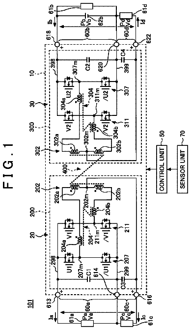
FIG. 1 is a block diagram for illustrating a schematic configuration of a power converter according to one embodiment of the present invention.
FIG. 2 is a block diagram for illustrating an example of a schematic configuration of a power converting unit illustrated in FIG. 1 .
FIG. 3 is a block diagram for illustrating an example of a phase-locked loop circuit used for the power converter illustrated in FIG. 1 .
FIG. 4 is a timing chart for illustrating signal waveforms from units of the power converter illustrated in FIG. 1 .
FIG. 5 is a timing chart for illustrating a monitoring method carried out by a cycle checking unit illustrated in FIG. 1 .
FIG. 6A and FIG. 6B are a diagram and a chart for illustrating a phase determination made by the cycle checking unit illustrated in FIG. 1 .
FIG. 7 is a diagram for illustrating a method of detecting and updating a current phase and a previous phase, which is carried out by the power converter illustrated in FIG. 1 .
FIG. 8 is a timing chart for illustrating signal waveforms from units of the power converter illustrated in FIG. 1 .
Description of embodiments
Now, a power converter for a vehicle as an example of a power converter according to an embodiment of the present invention is described with reference to the drawings. In each of the embodiments, the same or corresponding portions are denoted by the same reference symbols, and the overlapping description thereof is omitted. The present invention is not limited to the embodiment for a vehicle described below. First Embodiment
FIG. 1 is a block diagram for illustrating a schematic configuration of a power converter for a vehicle according to a first embodiment of the present invention. In the following description,
a U-phase higher arm is referred to as “UH phase”,
a U-phase lower arm is referred to as “UL phase”,
a V-phase higher arm is referred to as “VH phase”,
a V-phase lower arm is referred to as “VL phase”,
a W-phase higher arm is referred to as “WH phase”, and
a W-phase lower arm is referred to as “WL phase”.
In this case, the higher arm and the lower arm are distinguished from each other for each of three phases corresponding to U-, V-, and W-phases so that 2×3=6 phases are treated as a total number of phases.
In FIG. 1 , the power converter includes a gate control unit 120 and a power converting unit 11 . The power converting unit 11 is configured to perform power conversion based on a stator gate command signal S 16 generated in the gate control unit 120 . The gate control unit 120 is configured to generate the stator gate command signal S 16 based on a voltage detection signal S 11 output from the power converting unit 11 .
FIG. 2 is a block diagram for illustrating an example of a schematic configuration of the power converting unit illustrated in FIG. 1 . As illustrated in FIG. 2 , the power converting unit 11 includes a three-phase armature winding 313 provided to a stator and a field winding 314 provided to a rotator (also referred to as “rotor”) to form a rotating electric motor.
Further, the power converting unit 11 includes positive terminals P and FP and negative terminals N and FN. The positive terminals P and FP are connected to a positive side of a storage battery 44 , whereas the negative terminals N and FN are connected to a negative side of the storage battery 44 . A capacitor may be used in place of the storage battery 44 . A DC load voltage is applied as a positive voltage VP of the storage battery 44 , whereas a ground voltage is applied as a negative voltage VN of the storage battery 44 .
A U-phase higher arm switching element (hereinafter referred to as “UH element”) 31 , a U-phase lower arm switching element (hereinafter referred to as “UL element”) 33 , a V-phase higher arm switching element (hereinafter referred to as “VH element”) 35 , a V-phase lower arm switching element (hereinafter referred to as “VL element”) 37 , a W-phase higher arm switching element (hereinafter referred to as “WH element”) 39 , and a W-phase lower arm switching element (hereinafter referred to as “WL element”) 311 are provided on the stator side ( 313 ).
As the UH element 31 , the UL element 33 , the VH element 35 , the VL element 37 , the WH element 39 , and the WL element 311 , IGBTs, bipolar transistors, or field-effect transistors may be used.
A U-phase higher arm freewheeling diode (hereinafter referred to as “UH diode”) 32 is connected in parallel to the UH element 31 ,
a U-phase lower arm freewheeling diode (hereinafter referred to as “UL diode”) 34 is connected in parallel to the UL element 33 ,
a V-phase higher arm freewheeling diode (hereinafter referred to as “VH diode”) 36 is connected in parallel to the VH element 35 ,
a V-phase lower arm freewheeling diode (hereinafter referred to as “VL diode”) 38 is connected in parallel to the VL element 37 ,
a W-phase higher arm freewheeling diode (hereinafter referred to as “WH diode”) 310 is connected in parallel to the WH element 39 , and
a W-phase lower arm freewheeling diode (hereinafter referred to as “WL diode”) 312 is connected in parallel to the WL element 311 .
The UH element 31 , the UL element 33 , the VH element 35 , the VL element 37 , the WH element 39 , and the WL element 311 form a three-phase bridge circuit. A connection point between the UH element 31 and the UL element 33 is connected to a U-phase terminal of the armature winding 313 , a connection point between the VH element 35 and the VL element 37 is connected to a V-phase terminal of the armature winding 313 , and a connection point between the WH element 39 and the WL element 311 is connected to a W-phase terminal of the armature winding 313 , resulting in connection to the electric motor at equiangular intervals in a circular manner.
A connection point between the UH element 31 , the VH element 35 , and the WH element 39 is connected to the positive terminal P through a stator gate drive unit 315 , whereas a connection point between the UL element 33 , the VL element 37 , and the WL element 311 is connected to the negative terminal N through the stator gate drive unit 315 .
The stator gate drive unit 315 and a three-phase phase-voltage detecting unit 318 are provided on the stator side ( 313 ). The stator gate drive unit 315 is configured to drive a gate of the UH element 31 , a gate of the UL element 33 , a gate of the VH element 35 , a gate of the VL element 37 , a gate of the WH element 39 , and a gate of the WL element 311 based on the stator gate command signal S 16 so as to turn ON/OFF the UH element 31 , the UL element 33 , the VH element 35 , the VL element 37 , the WH element 39 , and the WL element 311 .
The three-phase phase-voltage detecting unit 318 is configured to detect a positive terminal voltage Vp to be applied to the connection point between the UH element 31 , the VH element 35 , and the WH element 39 , a negative terminal voltage Vn to be applied to the connection point between the UL element 33 , the VL element 37 , and the WL element 311 , a U-phase induction voltage Vu generated at the connection point between the UH element 31 and the UL element 33 , a V-phase induction voltage Vv generated at the connection point between the VH element 35 and the VL element 37 , and a W-phase induction voltage Vw generated at the connection point between the WH element 39 and the WL element 311 so as to output the resultant voltages as the voltage detection signal S 11 .
A field switching element 324 configured to perform pulse width modulation (PWM) control on a field current is provided on the rotor side ( 314 ). A field freewheeling diode 326 is connected in parallel to the field switching element 324 . As the field switching element 324 , an IGBT, a bipolar transistor, or a field effect transistor may be used.
A diode 325 is connected between a pair of electric wires respectively connected to both ends of the field wiring 314 . The field switching element 324 is placed in one of the electric wires, whereas a resistor 30 is placed in another thereof.
Further, a rotor gate drive unit 317 , a rotor gate command generating unit 319 , and a rotor current detecting unit 320 are provided on the rotor side. The rotor current detecting unit 320 is configured to output a detected value i.sub.rot of a rotor current based on a voltage across both ends of the resistor 30 . The rotor gate command generating unit 319 is configured to generate a rotor gate command signal S 21 based on the detected value i.sub.rot of the rotor current. The rotor gate drive unit 317 is configured to drive a gate of the field switching element 324 based on the rotor gate command signal S 21 so as to turn ON/OFF the field switching element 324 .
Although the three-phase field winding system generator motor including the three-phase armature winding 313 provided to the stator and the field winding 314 provided to the rotator is illustrated in FIG. 2 , the number of phases and the field system are not limited thereto. For example, a permanent magnet system including multiple phases other than three phases or the like may be used. Further, a generator motor apparatus of a separate structure system including the three-phase armature winding 313 included in the power converting unit 11 and the field winding 314 provided to the rotator, which are physically separated from other components, may be used without being limited to an integral structure generator motor that includes the power converting unit 11 in an integrated manner.
The gate drive unit 120 includes, as illustrated in FIG. 1 , a diode conducting state detecting unit 12 , a synchronization detection PLL unit 13 , a cycle checking unit 14 , a stator gate command generation PWM unit 15 , a stator gate ON-state detecting unit 16 , a stator gate command monitoring unit 17 , a diode ON-interval monitoring unit 18 , a diode ON-signal synthesizing unit (hereinafter referred to as “Don signal synthesizing unit”) 12 g , and a diode OFF-signal synthesizing unit (hereinafter referred to as “Doff signal synthesizing unit”) 12 ga.
The voltage detection signal S 11 is input to the diode conducting state detecting unit 12 so that ON timings and OFF timings of six diodes corresponding to the UH diode 32 , the UL diode 34 , the VH diode 36 , the VL diode 38 , the WH diode 310 , and the WL diode 312 illustrated in FIG. 2 are detected.
The diode conducting state detecting unit 12 includes:
a U-phase higher arm diode ON-signal detecting unit (hereinafter referred to as “UH-phase Don signal detecting unit”) 12 a;
a U-phase lower arm diode ON-signal detecting unit (hereinafter referred to as “UL-phase Don signal detecting unit”) 12 b;
a V-phase higher arm diode ON-signal detecting unit (hereinafter referred to as “VH-phase Don signal detecting unit”) 12 c;
a V-phase lower arm diode ON-signal detecting unit (hereinafter referred to as “VL-phase Don signal detecting unit”) 12 d;
a W-phase higher arm diode ON-signal detecting unit (hereinafter referred to as “WH-phase Don signal detecting unit”) 12 e;
a W-phase lower arm diode ON-signal detecting unit (hereinafter referred to as “WL-phase Don signal detecting unit”) 12 f;
a U-phase higher arm diode OFF-signal detecting unit (hereinafter referred to as “UH-phase Doff signal detecting unit”) 12 aa;
a U-phase lower arm diode OFF-signal detecting unit (hereinafter referred to as “UL-phase Doff signal detecting unit”) 12 ba;
a V-phase higher arm diode OFF-signal detecting unit (hereinafter referred to as “VH-phase Doff signal detecting unit”) 12 ca;
a V-phase lower arm diode OFF-signal detecting unit (hereinafter referred to as “VL-phase Doff signal detecting unit”) 12 da;
a W-phase higher arm diode OFF-signal detecting unit (hereinafter referred to as “WH-phase Doff signal detecting unit”) 12 ea ; and
a W-phase lower arm diode OFF-signal detecting unit (hereinafter referred to as “WL-phase Doff signal detecting unit”) 12 fa.
The UH-phase Don signal detecting unit 12 a is configured to output a U-phase higher arm diode ON detection signal (hereinafter referred to as “UH-phase Don detection signal”) S 12 uh based on the ON timing of the UH diode 32 .
The UL-phase Don signal detecting unit 12 b is configured to output a U-phase lower arm diode ON detection signal (hereinafter referred to as “UL-phase Don detection signal”) S 12 ul based on the ON timing of the UL diode 34 .
The VH-phase Don signal detecting unit 12 c is configured to output a V-phase higher arm diode ON detection signal (hereinafter referred to as “VH-phase Don detection signal”) S 12 vh based on the ON timing of the VH diode 36 .
The VL-phase Don signal detecting unit 12 d is configured to output a V-phase lower arm diode ON detection signal (hereinafter referred to as “VL-phase Don detection signal”) S 12 vl based on the ON timing of the VL diode 38 .
The WH-phase Don signal detecting unit 12 e is configured to output a W-phase higher arm diode ON detection signal (hereinafter referred to as “WH-phase Don detection signal”) S 12 wh based on the ON timing of the WH diode 310 .
The WL-phase Don signal detecting unit 12 f is configured to output a W-phase lower arm diode ON detection signal (hereinafter referred to as “WL-phase Don detection signal”) S 12 wl based on the ON timing of the WL diode 312 .
The UH-phase Doff signal detecting unit 12 aa is configured to output a U-phase higher arm diode OFF detection signal (hereinafter referred to as “UH-phase Doff detection signal”) S 12 uha based on the OFF timing of the UH diode 32 .
The UL-phase Doff signal detecting unit 12 ba is configured to output a U-phase lower arm diode OFF detection signal (hereinafter referred to as “UL-phase Doff detection signal”) S 12 ula based on the OFF timing of the UL diode 34 .
The VH-phase Doff signal detecting unit 12 ca is configured to output a V-phase higher arm diode OFF detection signal (hereinafter referred to as “VH-phase Doff detection signal”) S 12 vha based on the OFF timing of the VH diode 36 .
The VL-phase Doff signal detecting unit 12 da is configured to output a V-phase lower arm diode OFF detection signal (hereinafter referred to as “VL-phase Doff detection signal”) S 12 vla based on the OFF timing of the VL diode 38 .
The WH-phase Doff signal detecting unit 12 ea is configured to output a W-phase higher arm diode OFF detection signal (hereinafter referred to as “WH-phase Doff detection signal”) S 12 wha based on the OFF timing of the WH diode 310 .
The WL-phase Doff signal detecting unit 12 fa is configured to output a W-phase lower arm diode OFF detection signal (hereinafter referred to as “WL-phase Doff detection signal”) S 12 wla based on the OFF timing of the WL diode 312 .
For example, synchronous counters may be used as the UH-phase Don signal detecting unit 12 a , the UL-phase Don signal detecting unit 12 b , the VH-phase Don signal detecting unit 12 c , the VL-phase Don signal detecting unit 12 d , the WH-phase Don signal detecting unit 12 e , the WL-phase Don signal detecting unit 12 f , the UH-phase Doff signal detecting unit 12 aa , the UL-phase Doff signal detecting unit 12 ba , the VH-phase Doff signal detecting unit 12 ca , the VL-phase Doff signal detecting unit 12 da , the WH-phase Doff signal detecting unit 12 ea , and the WL-phase Doff signal detecting unit 12 fa.
Through the use of the synchronous counters, ON or OFF of the diodes is continuously detected within a predetermined time period so that whether the diodes are ON or OFF can be determined. As a result, a false detection caused by mixing of noise can be reduced.
The Don signal synthesizing unit 12 g is configured to generate a diode ON synthesized signal S 12 obtained by integrating the UH-phase Don detection signal S 12 uh , the UL-phase Don detection signal S 12 ul , the VH-phase Don detection signal S 12 vh , the VL-phase Don detection signal S 12 vl , the WH-phase Don detection signal S 12 wh , and the WL-phase Don detection signal S 12 wl in the same temporal sequence.
The Doff signal synthesizing unit 12 ga is configured to generate a diode OFF synthesized signal S 12 a obtained by integrating the UH-phase Doff detection signal S 12 uha , the UL-phase Doff detection signal S 12 ul a , the VH-phase Doff detection signal S 12 vha , the VL-phase Doff detection signal S 12 vl a , the WH-phase Doff detection signal S 12 wha , and the WL-phase Doff detection signal S 12 wla in the same temporal sequence.
For example, a six-input OR circuit may be used as each of the Don signal synthesizing unit 12 g and the Doff signal synthesizing unit 12 ga . The Don signal synthesizing unit 12 g may be configured so as to communalize (integrate in the same temporal sequence) outputs of the UH-phase Don signal detecting unit 12 a , the UL-phase Don signal detecting unit 12 b , the VH-phase Don signal detecting unit 12 c , the VL-phase Don signal detecting unit 12 d , the WH-phase Don signal detecting unit 12 e , and the WL-phase Don signal detecting unit 12 f through a buffer, whereas the Doff signal synthesizing unit 12 ga may be configured so as to communalize (integrate in the same temporal sequence) outputs of the UH-phase Doff signal detecting unit 12 aa , the UL-phase Doff signal detecting unit 12 ba , the VH-phase Doff signal detecting unit 12 ca , the VL-phase Doff signal detecting unit 12 da , the WH-phase Doff signal detecting unit 12 ea , and the WL-phase Doff signal detecting unit 12 fa through a buffer.
The synchronization detection PLL unit 13 is configured to generate an ON synchronized signal S 13 that has been subjected to synchronization control based on the diode ON synthesized signal S 12 and an OFF synchronized signal S 13 a that has been subjected to synchronization control based on the diode OFF synthesized signal S 12 a . Specifically, the synchronization detection PLL unit 13 may include an ON PLL circuit 121 and an OFF PLL circuit 122 . The ON PLL circuit 121 is configured to generate the ON synchronized signal S 13 that has been subjected to synchronization control based on the diode ON synthesized signal S 12 . The OFF PLL circuit 122 is configured to generate the OFF synchronized signal S 13 a that has been subjected to synchronization control based on the diode OFF synthesized signal S 12 a.
The ON synchronized signal S 13 and the OFF synchronized signal S 13 a can be generated independently of each other. Specifically, the synchronization detection PLL unit 13 may include the ON PLL circuit 121 and the OFF PLL circuit 122 . The ON PLL circuit 121 may be configured to generate the ON synchronized signal S 13 that has been subjected to the synchronization control based on the diode ON synthesized signal S 12 . The OFF PLL circuit 122 may be configured to generate the OFF synchronized signal S 13 a that has been subjected to the synchronization control based on the diode OFF synthesized signal S 12 a.
FIG. 3 is a block diagram for illustrating an example of a phase-locked loop circuit to be used in each of the ON PLL circuit 121 and the OFF PLL circuit 122 of the synchronization detection PLL unit 13 of the power converter illustrated in FIG. 1 . In FIG. 3 , the phase-locked loop circuit (PLL) 51 includes a 1/n divider 52 , a phase comparator (PD) 53 , a PI controller (P (proportional) I (integral) control) 54 , and a voltage control oscillator (VCO) 55 . A low-pass filter may be used in place of the PI controller 54 .
An oscillation signal ω′ generated in the voltage control oscillator 55 is divided by n (n is a positive integer) in the 1/n divider 52 and is then input to the phase comparator 53 . A waveform of the oscillation signal ω* may be a sine wave W 1 or a square wave W 2 . Then, the oscillation signal ω* is compared with an externally input periodic signal Sy in phase in the phase comparator 53 . A result of the comparison is input to the voltage control oscillator 55 through the PI controller 54 , thereby controlling a frequency of the oscillation signal ω* so that the phase of the oscillation signal ω* becomes equal to the phase of the periodic signal Sy. Then, the oscillation signal ω* is integrated in an integrator (1/s) 56 to generate a triangular wave signal θ*. Assuming that the frequency of the oscillation signal ω* is f, the oscillation signal ω* is converted into an angular velocity based on an expression: ω*=2πf and is then integrated in the integrator 56 , thereby obtaining an estimated output of the angular position.
When the phase-locked loop circuit 51 and the integrator 56 are used for the ON PLL circuit 121 illustrated in FIG. 1 , the triangular wave signal θ* is output as the ON synchronized signal S 13 by using the diode ON synthesized signal S 12 as the periodic signal Sy.
When the phase-locked loop circuit 51 and the integrator 56 are used for the OFF PLL circuit 122 illustrated in FIG. 1 , the triangular wave signal θ* is output as the OFF synchronized signal S 13 a by using the diode OFF synthesized signal S 12 a as the periodic signal Sy.
In FIG. 1 , the cycle checking unit 14 is configured to compare the UH-phase Don detection signal S 12 uh , the UL-phase Don detection signal S 12 ul , the VH-phase Don detection signal S 12 vh , the VL-phase Don detection signal S 12 vl , the WH-phase Don detection signal S 12 wh , the WL-phase Don detection signal S 12 wl , the UH-phase Doff detection signal S 12 uha , the UL-phase Doff detection signal S 12 ul a , the VH-phase Doff detection signal S 12 vha , the VL-phase Doff detection signal S 12 vla , the WH-phase Doff detection signal S 12 wha , and the WL-phase Doff detection signal S 12 wla with the ON synchronized signal S 13 and the OFF synchronized signal S 13 a so as to monitor whether or not cycles of the U-phase induction voltage Vu, the V-phase induction voltage Vv, and the W-phase induction voltage Vw and an order of detection are correct over all the phases.
The stator gate command generation PWM unit 15 is configured to generate the gate command signal S 16 for performing switching control on the UH element 31 , the UL element 33 , the VH element 35 , the VL element 37 , the WH element 39 , and the WL element 311 based on the ON synchronized signal S 13 and the OFF synchronized signal S 13 a.
In this case, the stator gate command generation PWM unit 15 includes:
a U-phase higher arm ON triangular wave generating unit (UH-phase On PWM) 15 a;
a U-phase higher arm OFF triangular wave generating unit (UH-phase Off PWM) 15 aa;
a U-phase higher arm gate command signal generating unit (UH-phase SW) 15 ab;
a U-phase lower arm ON triangular wave generating unit (UL-phase On PWM) 15 b;
a U-phase lower arm OFF triangular wave generating unit (UL-phase Off PWM) 15 ba;
a U-phase lower arm gate command signal generating unit (UL-phase SW) 15 bb;
a V-phase higher arm ON triangular wave generating unit (VH-phase On PWM) 15 c;
a V-phase higher arm OFF triangular wave generating unit (VH-phase Off PWM) 15 ca;
a V-phase higher arm gate command signal generating unit (VH-phase SW) 15 cb;
a V-phase lower arm ON triangular wave generating unit (VL-phase On PWM) 15 d;
a V-phase lower arm OFF triangular wave generating unit (VL-phase Off PWM) 15 da;
a V-phase lower arm gate command signal generating unit (VL-phase SW) 15 db;
a W-phase higher arm ON triangular wave generating unit (WH-phase On PWM) 15 e;
a W-phase higher arm OFF triangular wave generating unit (WH-phase Off PWM) 15 ea;
a W-phase higher arm gate command signal generating unit (WH-phase SW) 15 eb;
a W-phase lower arm ON triangular wave generating unit (WL-phase On PWM) 15 f;
a W-phase lower arm OFF triangular wave generating unit (WL-phase Off PWM) 15 fa ; and
a W-phase lower arm gate command signal generating unit (WL-phase SW) 15 fb.
The U-phase higher arm ON triangular wave generating unit 15 a is configured to generate a U-phase higher arm ON triangular wave (hereinafter referred to as “UH-phase ON triangular wave”) S 15 uh based on the ON synchronized signal S 13 output from a previous ON timing to a current ON timing of the UH diode 32 , each timing being indicated by the UH-phase Don detection signal S 12 uh.
The U-phase higher arm OFF triangular wave generating unit 15 aa is configured to generate a U-phase higher arm OFF triangular wave (hereinafter referred to as “UH-phase OFF triangular wave”) S 15 uha based on the OFF synchronized signal S 13 a output from a previous OFF timing to a current OFF timing of the UH diode 32 , each timing being indicated by the UH-phase Doff detection signal S 12 uha.
The U-phase higher arm gate command signal generating unit 15 ab is configured to generate a gate command signal S 16 uh for the UH element 31 based on a result of comparison between the UH-phase ON triangular wave S 15 uh and the UH-phase OFF triangular wave S 15 uha.
The U-phase lower arm ON triangular wave generating unit 15 b is configured to generate a U-phase lower arm ON triangular wave (hereinafter referred to as “UL-phase ON triangular wave”) S 15 ul based on the ON synchronized signal S 13 output from a previous ON timing to a current ON timing of the UL diode 34 , each timing being indicated by the UL-phase Don detection signal S 12 ul.
The U-phase lower arm OFF triangular wave generating unit 15 ba is configured to generate a U-phase lower arm OFF triangular wave (hereinafter referred to as “UH-phase OFF triangular wave”) S 15 ula based on the OFF synchronized signal S 13 a output from a previous OFF timing to a current OFF timing of the UL diode 34 , each timing being indicated by the UL-phase Doff detection signal S 12 ula.
The U-phase lower arm gate command signal generating unit 15 bb is configured to generate a gate command signal S 16 ul for the UL element 33 based on a result of comparison between the UL-phase ON triangular wave S 15 ul and the UL-phase OFF triangular wave S 15 ula.
The V-phase higher arm ON triangular wave generating unit 15 c is configured to generate a V-phase higher arm ON triangular wave (hereinafter referred to as “VH-phase ON triangular wave”) S 15 vh based on the ON synchronized signal S 13 output from a previous ON timing to a current ON timing of the VH diode 36 , each timing being indicated by the VH-phase Don detection signal S 12 vh.
The V-phase higher arm OFF triangular wave generating unit 15 ca is configured to generate a V-phase higher arm OFF triangular wave (hereinafter referred to as “VH-phase OFF triangular wave”) S 15 vha based on the OFF synchronized signal S 13 a output from a previous OFF timing to a current OFF timing of the VH diode 36 , each timing being indicated by the VH-phase Doff detection signal S 12 vha.
The V-phase higher arm gate command signal generating unit 15 cb is configured to generate a gate command signal S 16 vh for the VH element 35 based on a result of comparison between the VH-phase ON triangular wave S 15 vh and the VH-phase OFF triangular wave S 15 vha.
The V-phase lower arm ON triangular wave generating unit 15 d is configured to generate a V-phase lower arm ON triangular wave (hereinafter referred to as “VL-phase ON triangular wave”) S 15 vl based on the ON synchronized signal S 13 output from a previous ON timing to a current ON timing of the VL diode 38 , each timing being indicated by the VL-phase Don detection signal S 12 vl.
The V-phase lower arm OFF triangular wave generating unit 15 da is configured to generate a V-phase lower arm OFF triangular wave (hereinafter referred to as “VL-phase OFF triangular wave”) S 15 vla based on the OFF synchronized signal S 13 a output from a previous OFF timing to a current OFF timing of the VL diode 38 , each timing being indicated by the VL-phase Doff detection signal S 12 vl a.
The V-phase lower arm gate command signal generating unit 15 db is configured to generate a gate command signal S 16 vl for the VL element 37 based on a result of comparison between the VL-phase ON triangular wave S 15 vl and the VL-phase OFF triangular wave S 15 vl a.
The W-phase higher arm ON triangular wave generating unit 15 e is configured to generate a W-phase higher arm ON triangular wave (hereinafter referred to as “WH-phase ON triangular wave”) S 15 wh based on the ON synchronized signal S 13 output from a previous ON timing to a current ON timing of the WH diode 310 , each timing being indicated by the WH-phase Don detection signal S 12 wh.
The W-phase higher arm OFF triangular wave generating unit 15 ea is configured to generate a W-phase higher arm OFF triangular wave (hereinafter referred to as “WH-phase OFF triangular wave”) S 15 wha based on the OFF synchronized signal S 13 a output from a previous OFF timing to a current OFF timing of the WH diode 310 , each timing being indicated by the WH-phase Doff detection signal S 12 wha.
The W-phase higher arm gate command signal generating unit 15 eb is configured to generate a gate command signal S 16 vh for the WH element 39 based on a result of comparison between the WH-phase ON triangular wave S 15 wh and the WH-phase OFF triangular wave S 15 wha.
The W-phase lower arm ON triangular wave generating unit 15 f is configured to generate a W-phase lower arm ON triangular wave (hereinafter referred to as “WL-phase ON triangular wave”) S 15 wl based on the ON synchronized signal S 13 output from a previous ON timing to a current ON timing of the WL diode 312 , each timing being indicated by the WL-phase Don detection signal S 12 wl.
The W-phase lower arm OFF triangular wave generating unit 15 fa is configured to generate a W-phase lower arm OFF triangular wave (hereinafter referred to as “WL-phase OFF triangular wave”) S 15 wla based on the OFF synchronized signal S 13 a output from a previous OFF timing to a current OFF timing of the WL diode 312 , each timing being indicated by the WL-phase Doff detection signal S 12 wla.
The W-phase lower arm gate command signal generating unit 15 fb is configured to generate a gate command signal S 16 wl for the WL element 311 based on a result of comparison between the WL-phase ON triangular wave S 15 wl and the WL-phase OFF triangular wave S 15 wla.
FIG. 4 is a timing chart for illustrating signal waveforms from the units of the power converter illustrated in FIG. 1 . In an example of FIG. 4 , (a) the UH-phase Don detection signal S 12 uh , (c) the UL-phase Don detection signal S 12 ul , (b) the UH-phase Doff detection signal S 12 uha , and (d) the UL-phase Doff detection signal S 12 ula of the U-phase are illustrated, and the description is omitted for the VH-phase Don detection signal S 12 vh , the VL-phase Don detection signal S 12 vl , the WH-phase Don detection signal S 12 wh , the WL-phase Don detection signal S 12 wl , the VH-phase Doff detection signal S 12 vha , the VL-phase Doff detection signal S 12 vla , the WH-phase Doff detection signal S 12 wha , and the WL-phase Doff detection signal S 12 wla of the V-phase and the W-phase.
Further, (e) the U-phase induction voltage signal Vu, (f) the V-phase induction voltage signal Vv, (g) the W-phase induction voltage signal Vw, (h) the ON synchronized signal S 13 , and (i) the OFF synchronized signal S 13 a are illustrated.
Further, in the example of FIG. 4 , (j) the UH-phase ON triangular wave S 15 uh , (k) the UH-phase OFF triangular wave S 15 uha , (l) the VH-phase ON triangular wave S 15 vh , (m) the VH-phase OFF triangular wave S 15 vha , (n) the WH-phase ON triangular wave S 15 wh , and (o) the WH-phase OFF triangular wave S 15 wha of the higher arm side of the three phases are illustrated, and the description is omitted for the UL-phase ON triangular wave S 15 ul , the UL-phase OFF triangular wave S 15 ula , the VL-phase ON triangular wave S 15 vl , the VL-phase OFF triangular wave S 15 vla , the WL-phase ON triangular wave S 15 wl , and the WL-phase OFF triangular wave S 15 wla of the three phases on the lower arm side.
In FIG. 4 , the gate of the UH element 31 , the gate of the UL element 33 , the gate of the VH element 35 , the gate of the VL element 37 , the gate of the WH element 39 , and the gate of the WL element 311 illustrated in FIG. 2 are driven by the stator gate drive unit 315 so that a DC set by the positive terminal voltage Vp and the negative terminal voltage Vn is converted into a three-phase AC that is then applied to the U-phase terminal, the V-phase terminal, and the W-phase terminal of the armature winding 313 .
Further, the gate of the field switching element 324 illustrated in FIG. 2 is driven by the rotor gate drive unit 317 so that a DC set by the positive terminal voltage VFp and the negative terminal voltage VFn is converted into an AC that is then applied across both ends of the field winding 314 . Then, the rotor current flowing through the field winding 314 is converted into a voltage by the resistor 30 so that the voltage across both ends of the resistor 30 is input to the rotor current detecting unit 320 . The rotor current detecting unit 320 outputs a signal indicating the detected value i.sub.rot of the rotor current to the rotor gate command generating unit 319 in accordance with the voltage applied across the both ends of the resistor 30 .
Then, the rotor gate command signal S 21 is generated based on the detected value i.sub.rot of the rotor current in the rotor gate command generating unit 319 . The rotor gate command signal S 21 is then input to the rotor gate drive unit 317 to drive the gate of the field switching element 324 .
On the other hand, the positive terminal voltage Vp, the negative terminal voltage Vn, the U-phase induction voltage Vu, the V-phase induction voltage Vv, and the W-phase induction voltage Vw are detected in the three-phase phase-voltage detecting unit 318 , and are then input as the voltage detection signal S 11 to the diode conducting state detecting unit 12 illustrated in FIG. 1 .
Then, the diode conducting state detecting unit 12 detects a diode ON state when a forward current flows through the UH diode 32 , the UL diode 34 , the VH diode 36 , the VL diode 38 , the WH diode 310 , and the WL diode 312 to generate a forward voltage Vf across both ends thereof.
Further, the diode conducting state detecting unit 12 detects a diode OFF state when a forward current does not flow through the UH diode 32 , the UL diode 34 , the VH diode 36 , the VL diode 38 , the WH diode 310 , and the WL diode 312 and no forward voltage Vf is generated because both ends thereof are open.
The description continues in the full USPTO document.
 Lapsed, fee not paid6 drawings