Lapsed, fee not paid11 drawings
Energy & Sustainability · US 9,780,615 B2
Motor winding structure
A motor winding structure includes a base plate is disclosed.
US 9,780,665 B2 · Assignee: GM GLOBAL TECHNOLOGY OPERATIONS LLC · Inventors: Li; Lihua et al.
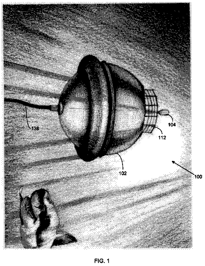
Sheet 1 of 5 from the published document. All sheets in the USPTO PDF
Methods and systems are provided for control operation of a boost converter. The boost converter includes an input, an output, and a plurality of paths electrically connecting the input to the output. The boost converter also includes a plurality of switches disposed along the paths to control current flow between the input and the output. The system includes a controller. The controller receives a desired current to be supplied at the output. The controller determines which of the paths to utilize based at least in part on the desired current. The controller controls the switches based at least in part on the determination of which of the paths to utilize.
Electric, hybrid electric, and fuel cell vehicles typically utilize a high voltage power distribution system to deliver high voltage DC power to an electric drive motor and other electrical devices. The high voltage necessary for a vehicular drive motor is often on the order of 300-500 V. In order to achieve these necessary high voltages, power distribution systems may implement a boost converter, also commonly referred to as a step-up converter. Such a boost converter permits the batteries and/or power sources, e.g. a fuel cell, to store and deliver lower voltages than would be required without a boost converter. However, typical operation of vehicle boost converters is often inefficient. Moreover, when coupled to a fuel cell, the boost converter may cause stress to an upper-level stack of the fuel cell, due to current ripple. Furthermore, electrical and electronic components of the boo
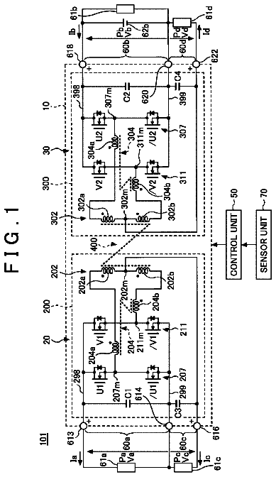
All 5 drawing sheets from the published document, cropped to the drawing.
What the patent claimed, word for word. All of it is now free to use.
The technical field generally relates to operation and control of boost converters, and more particularly relates to operation and control of direct current (DC) boost converters for a vehicle.
Electric, hybrid electric, and fuel cell vehicles typically utilize a high voltage power distribution system to deliver high voltage DC power to an electric drive motor and other electrical devices. The high voltage necessary for a vehicular drive motor is often on the order of 300-500 V. In order to achieve these necessary high voltages, power distribution systems may implement a boost converter, also commonly referred to as a step-up converter. Such a boost converter permits the batteries and/or power sources, e.g. a fuel cell, to store and deliver lower voltages than would be required without a boost converter.
However, typical operation of vehicle boost converters is often inefficient. Moreover, when coupled to a fuel cell, the boost converter may cause stress to an upper-level stack of the fuel cell, due to current ripple. Furthermore, electrical and electronic components of the boost converter may rapidly wear out due to unnecessary overuse.
Accordingly, it is desirable to provide a system and method for achieving high efficiency operation of a boost converter. In addition, it is desirable to provide a system and method of operating a boost converter that will reduce stress on connected components, such as a fuel cell. It is also desirable to increase component life of a boost converter. Furthermore, other desirable features and characteristics of the present invention will become apparent from the subsequent detailed description and the appended claims, taken in conjunction with the accompanying drawings and the foregoing technical field and background.
A method is provided for controlling operation of a boost converter using a controller. The boost converter includes an input, an output, and a plurality of paths electrically connecting the input to the output. The boost converter also includes a plurality of switches disposed along the paths to control current flow between the input and the output. The method comprises receiving a desired current at the controller. The method further comprises determining which of the paths to utilize based at least in part on the desired current. The method also comprises controlling the switches with the controller based at least in part on the determination of which of the paths to utilize.
A system is also provided. The system includes a boost converter. The boost converter includes an input, an output, and a plurality of paths electrically connecting the input to said output. The boost converter further includes a plurality of switches disposed along the paths to control current flow between the input and the output. The system includes a controller for receiving a desired current, determining which of the paths to utilize based at least in part on the desired current, and controlling the switches based at least in part on the determination of which of the paths to utilize.
The present invention will hereinafter be described in conjunction with the following drawing figures, wherein like numerals denote like elements, and
FIG. 1 is a block diagram of one embodiment of a power distribution system for a vehicle showing a boost converter operatively connecting a power source to a high voltage bus;
FIG. 2 is an electrical schematic diagram of the boost converter according to one embodiment having a plurality of electrical paths to conduct current therethrough;
FIG. 3 is a flowchart showing one exemplary method of determining which of the paths of the boost converter to utilize;
FIG. 4 is a timing diagram showing operation of switches of the boost converter in one path operation;
FIG. 5 is a timing diagram showing operation of the switches of the boost converter in two path operation; and
FIG. 6 is a timing diagram showing operation of the switches of the boost converter in three path operation.
The following detailed description is merely exemplary in nature and is not intended to limit the invention or the application and uses of the invention. Furthermore, there is no intention to be bound by any expressed or implied theory presented in the preceding technical field, background, brief summary or the following detailed description.
Referring to the figures, wherein like numerals indicate like parts throughout the several views, a power distribution system 100 for a vehicle 102 and method for controlling a power distribution system 100 is shown and/or described herein.
With reference to FIG. 1 , the system 100 includes a power source 104 for generating electrical power. In the illustrated embodiment, the power source 104 is implemented as a fuel cell (not separately numbered) for generating the electrical power from a fuel, e.g., hydrogen. (However, the fuel cell may be fueled by other fuels besides hydrogen.) More specifically, the fuel cell of the illustrated embodiment comprises a plurality of fuel cell stacks connected in series. The system 100 of the illustrated embodiment also includes a compressor 106 to supply air to the fuel cell. The power source 104 of the illustrated embodiment produces electrical power having a direct current (“DC”). In other embodiments, the power source 104 may be implemented as an alternator (not shown) coupled to an internal combustion engine (not shown) as the power source 104 . The alternator produces an alternating current (“AC”) which may, or may not, be converted to DC depending on the particular embodiment implemented.
The system 100 also includes a boost converter 108 for boosting (i.e., raising) the voltage generated by the power source 104 . The boost converter 108 may also be referred to as a step-up converter. The boost converter 108 includes at least one input 110 and at least one output 112 . In the illustrated embodiment, a single input 110 and a single output 112 are utilized. In operation, a voltage at the output 112 is higher than a voltage at the input 110 . In the illustrated fuel cell embodiment, a stack interface unit (“SIU”) 114 operatively connects the fuel cell stacks of the power source 104 to the input 110 of the boost converter 108 .
The system 100 includes a controller 115 in communication with the boost converter 108 for controlling operation of the boost converter 108 . The controller 115 includes a memory (not shown) for storing data and processing logic (not shown) for executing instructions, e.g., a software program. The controller 115 may comprise a microprocessor, a microcontroller, an application specific integrated circuit, and/or other logic devices. Algorithms and techniques for controlling the boost converter 108 utilizing the controller 115 are discussed in further detail below.
Referring now to FIG. 2 , the boost converter 108 of the illustrated embodiment includes a plurality of paths 216 a , 216 b , 216 c electrically connecting the input 110 to the output 112 . Specifically, the paths 216 a , 216 b , 216 c of the illustrated embodiment are denoted as a first path 216 a , a second path 216 b , and a third path 216 c , each extending from the input 110 . In other embodiments, however, the boost converter 108 may utilize any number of power paths.
In the illustrated embodiment, each path 216 a , 216 b , 216 c of the boost converter 108 includes an inductor 218 a , 218 b , 218 c electrically connected to the input 110 . As such, current flows through each inductor 218 a , 218 b , 218 c and along each respective path 216 a , 216 b , 216 c.
The boost converter 108 further includes a plurality of switches 220 a , 220 b , 220 c . Each switch 220 a , 220 b , 220 c is disposed along one of the paths 216 a , 216 b , 216 c to control current flow between the input 110 and the output 112 .
In the illustrated embodiment, each switch 220 a , 220 b , 220 c is implemented with an insulated gate bipolar transistor (“IGBT”) 222 a , 222 b , 222 c and a diode 223 a , 223 b , 223 c . Each IGBT 222 a , 222 b , 222 c includes a gate, a collector, and an emitter (not numbered). Specifically, the collector of each IGBT 222 a , 222 b , 222 c is electrically connected to one of the inductors 218 a , 218 b , 218 c , each emitter is electrically connected to ground (or other reference potential, such as the vehicle chassis), and each gate is coupled to the controller 115 . As such, the controller 115 may control operation (i.e., activation) of each IGBT 222 a , 222 b , 222 c . The diodes 223 a , 223 b , 223 c are disposed in parallel with the collector and emitters of the respective IGBTs 222 a , 222 b , 222 c , as shown in FIG. 2 .
The system 100 may include one or more temperature sensors 224 a , 224 b , 224 c for sensing the temperatures of the inductors 218 a , 218 b , 218 c , the switches 220 a , 220 b , 220 c , the diodes 223 a , 223 b , 223 c , and/or other electrical or electronic components. The temperature sensors 224 a , 224 b , 224 c are in communication with the controller 115 to communicate temperature data to the controller 115 . As such, the controller 115 may utilize temperature data in the process of controlling operation of the boost converter 108 , as described in further detail below.
Specifically, in the illustrated embodiment, the temperature sensors 224 a , 224 b , 224 c are thermistors, and more specifically, negative temperature coefficient (“NTC”) thermistors. Although FIG. 2 only shows the temperature sensors 224 a , 224 b , 224 c in proximity to the switches 220 a , 220 b , 220 c , it is to be appreciated that additional temperature sensors may be implemented to sense the temperatures of the inductors 218 a , 218 b , 218 c , diodes 223 a , 223 b , 223 c , and/or other electrical or electronic components as stated above. Furthermore, other devices and techniques may be implemented to sense temperature, other than thermistors.
The boost converter 108 of the illustrated embodiment further includes a plurality of diodes 225 a , 225 b , 225 c for rectifying the flow of current, i.e., acting as a passive switch, through the paths 216 a , 216 b , 216 c as is shown in FIG. 2 . Also, a capacitor 226 is electrically connected to output 112 .
The system 100 of the illustrated embodiment further includes a distribution bus 128 . The distribution bus 128 is electrically connected to the output 112 of the boost converter 108 . The distribution bus 128 of the illustrated embodiment may also be referred to as a high voltage bus, reflecting the high voltage generated by the boost converter 108 . The distribution bus 128 distributes electrical power to various loads 130 of the vehicle 102 , including, but certainly not limited to, a drive motor (not separately numbered) for driving wheels 132 of the vehicle 102 . The system 100 may include one or more DC-to-AC converters 134 electrically connected to distribution bus 128 . The DC-to-AC converters 134 convert the DC power of the distribution bus 128 to AC power to be utilized by the AC loads 130 .
The system 100 of the illustrated embodiment also includes a battery 136 for storing electricity. The battery 136 may comprise one or more electrical cells (not shown) as is well known in the art. The battery 136 is electrically connected to the distribution bus 128 . As such, the battery 136 may be charged with power from the distribution bus 128 , e.g., power generated by the power source 104 . The battery 136 may also supply power to the distribution bus 128 and, accordingly, the loads 130 .
The controller 115 may comprise a microprocessor, a microcontroller, an application specific integrated circuit (“ASIC”), and/or other logic device capable of performing calculations, storing data, and/or executing instructions. The controller 115 of the illustrated embodiment implements one or more methods for controlling operation of the boost converter 108 . However, the methods described herein may alternatively be practice with systems and boost converters other than the system 100 and boost converter 108 described above.
One exemplary method includes receiving a desired current. In the illustrated embodiment, the desired current is the current to be drawn from the fuel cell 104 at the input 110 of the boost converter 108 . Also, in the illustrated embodiment, the desired current is received by the controller 115 from a vehicle computer (not shown) which determines how much current is necessary based on the operation or desired operation the loads 130 . In another embodiment, the desired current is calculated internally by the controller 115 .
The method also includes determining which of the paths 216 a , 216 b , 216 c to utilize. That is, the method includes determining which of the paths 216 a , 216 b , 216 c will be implemented in providing power from the input 110 to the output 112 of the boost converter 108 . In the illustrated embodiment, the method includes determining which of the first, second, and third paths 216 a , 216 b , 216 c will be utilized to supply power to the distribution bus 128 via the output 112 of the boost converter 108 .
One step in determining which of the paths 216 a , 216 b , 216 c to utilize is determining whether each of the paths 216 a , 216 b , 216 c is available or unavailable. To determine whether a path 216 a , 216 b , 216 c is available, the controller 115 receives inputs regarding faults on each path 216 a , 216 b , 216 c . For examples, in the illustrated embodiments, the IGBTs 222 a , 222 b , 222 c may send a de-saturation fault signal to the controller 115 . In response to receiving a fault signal, the controller 115 may exclude use of a path 216 a , 216 b , 216 c . Furthermore, the controller 115 may perform other internal calculations to determine whether one or more of the paths 216 a , 216 b , 216 c are faulted. As a result of these calculations, the controller 115 may exclude use of the one or more faulted paths 216 a , 216 b , 216 c . That is, the controller 115 may mark the faulted paths 216 a , 216 b , 216 c as “unavailable” and refrain from their use.
Yet another step in determining which of the paths 216 a , 216 b , 216 c to utilize involves ranking the “health” of each paths 216 a , 216 b , 216 c . The health of each path 216 a , 216 b , 216 c may be based on one or more factors, i.e., health factors. One health factor may be the temperature of electrical and/or electronic components (not separately numbered) along the path 216 a , 216 b , 216 c . Typically, the higher a temperature of such electrical and/or electronic components along the path 216 a , 216 b , 216 c indicates a less desirable path, as excessive temperature can reduce current flow and may result in damage to the components. Of course, other health factors may be utilized in determining the health of a path 216 a , 216 b , 216 c , besides the temperature of electrical and/or electronic components.
In the illustrated embodiment, the factors for ranking the health of each path 216 a , 216 b , 216 c include the temperatures of the inductors 218 a , 218 b , 218 c , the IGBTs 222 a , 222 b , 222 c , and the diodes 223 a , 223 b , 223 c disposed along the respective path 216 a , 216 b , 216 c . Specifically, in the illustrated embodiment, the path 216 a , 216 b , 216 c having the highest temperature of an inductor 218 a , 218 b , 218 c , an IGBT 222 a , 222 b , 222 c , or a diode 223 a , 223 b , 223 c is categorized as the worst path 216 a , 216 b , 216 c , and thus least desirable for conducting electrical power. The next highest temperature on a different path 216 a , 216 b , 216 c is categorized as the second worst path, and so on.
In another embodiment, the method includes sensing the temperature of each of the IGBTs 222 a , 222 b , 222 c and then ranking the paths 216 a , 216 b , 216 c that have the lowest temperatures of the IGBTs 222 a , 222 b , 222 c to be utilized. In yet another embodiment, the method includes sensing the temperature of each of the inductors 218 a , 218 b , 218 c and then ranking the paths 216 a , 216 b , 216 c that have the lowest temperatures of the inductors 218 a , 218 b , 218 c to be utilized. In yet another embodiment, the method includes sensing the temperatures of each of the IGBTs 222 a , 222 b , 222 c and each of the inductors 218 a , 218 b , 218 c , finding the average temperatures of the IGBTs 222 a , 222 b , 222 c and the inductors 218 a , 218 b , 218 c along each path 216 a , 216 b , 216 c , and then ranking the paths 216 a , 216 b , 216 c that have the lowest average temperatures to be utilized. Specifically, the path 222 a , 222 b , 222 c having the lowest average temperature of the inductor 218 a , 218 b , 218 c and the IGBT 222 a , 222 b , 222 c would be ranked as most desirable for conducting electrical power, the path 222 a , 222 b , 222 c having the second lowest average temperature would be ranked as the second most desirable, and the path 222 a , 222 b , 222 c having with the highest average temperature would be ranked as least desirable for conducting electrical power.
When the health of each path 216 a , 216 b , 216 c is identical or substantially similar, the ranking of the paths 216 a , 216 b , 216 c for conducting electrical power is based on the amount of use that each path 216 a , 216 b , 216 c has historically endured. Specifically, in the illustrated embodiment, when each path 216 a , 216 b , 216 c is utilized to supply power therethrough, the controller 115 records the amount of time that each path 216 a , 216 b , 216 c is utilized. The path 216 a , 216 b , 216 c with the lowest operation time is ranked as the most desirable for conducting electrical power, the path 216 a , 216 b , 216 c with the second lowest operation time is ranked as the second most desirable, while the path 216 a , 216 b , 216 c having the highest operation time is ranked as the least desirable.
Yet another step in determining which of the paths 216 a , 216 b , 216 c to utilize is determining how many of the paths 216 a , 216 b , 216 c need to be utilized based on the received desired current. Said another way, a minimum number of paths 216 a , 216 b , 216 c necessary to draw the desired current must be determined. In the illustrated embodiment, the software program running on the controller 115 determines if one, two, or all three of the paths 216 a , 216 b , 216 c are necessary to draw the desired current from the input 110 of the boost converter 108 .
For example, the software may include a first predetermined threshold value and a second predetermined threshold value, with the second predetermined threshold being greater than the first predetermined threshold value. If the desired current is lower than the first predetermined threshold value, then only one of the paths 216 a , 216 b , 216 c need to be utilized. If the desired current is greater than the first predetermined threshold value, but lower than the second predetermined threshold value, then two of the paths 216 a , 216 b , 216 c need to be utilized. Finally, if the desired current is greater than the second predetermined threshold value, then all three of the paths 216 a , 216 b , 216 c need to be utilized.
By utilizing only the number of paths 216 a , 216 b , 216 c actually necessary to draw the desired current, the boost converter 108 of the disclosed system 100 achieves greater efficiency than conventional boost converters, where each path is always in operation. Furthermore, if the desired current is greater than the current that available to be received by the boost converter 108 , due to faulted paths 216 a , 216 b , 216 c , etc., then the controller 115 initiates a warning message. The warning message may be delivered to the driver of the vehicle 102 and/or sent to the vehicle computer.
Furthermore, another step in determining which of the paths 216 a , 216 b , 216 c to utilize is selecting the paths 216 a , 216 b , 216 c based on how many of the paths need to be utilized in combination with the ranking of the health of each path 216 a , 216 b , 216 c as described above. For example, if it is determined that two paths 216 a , 216 b , 216 c need to be utilized and the ranking of the paths 216 a , 216 b , 216 c from highest to lowest is the second path 216 b , the third path 216 c , and the first path 216 a , then the second and third paths 216 b , 216 c will be selected to be utilized to conduct the electrical power through the boost converter 108 .
A flowchart showing an exemplary method 300 can be seen with reference to FIG. 3 . Specifically, the method 300 includes the step 302 of determining if any of the paths 216 a , 216 b , 216 c of the boost converter 108 are faulted. If any of the paths 216 a , 216 b , 216 c are faulted, then the method proceeds to the step 304 of excluding faulted paths 216 a , 216 b , 216 c from being utilized. After step 304 , or if none of the paths 216 a , 216 b , 216 c are faulted, the method 300 proceeds with the step 306 of sensing temperatures of electrical/electronic components of the boost converter 108 .
The method 300 then includes the step 308 of determining if any of the temperatures sensed in step 306 are substantially similar. If the temperatures are substantially similar, then the method 300 includes the step 310 of ranking the available paths 216 a , 216 b , 216 c based on cumulative time of use. If the temperatures sensed in step 306 are not substantially similar, then the method 300 includes the step 312 of ranking the available paths 216 a , 216 b , 216 c based on temperature.
After steps 310 or 312 , the method 300 further includes the step 314 of receiving a desired current to be drawn by the boost converter 108 . Next, the method 300 includes the step 316 of determining the number of paths 216 a , 216 b , 216 c necessary based on the desired current. The method 300 then includes the step 318 of selecting the paths 216 a , 216 b , 216 c to utilize based on number necessary and ranking (from steps 310 or 312 ).
The method of the disclosure also includes controlling the switches 220 a , 220 b , 220 c to regulate the flow of current through the paths 216 a , 216 b , 216 c . The switches 220 a , 220 b , 220 c corresponding with the selected paths 216 a , 216 b , 216 c to be utilized, as described above, alternate between an “on” state and an “off” state. Thus, “on” pulses (not labeled) are created for the controlled switches 220 a , 220 b , 220 c . More specifically, in the illustrated embodiment, the switching period, i.e., the time between one “on” state to the next “on” state, is about 60 μs. The switches 220 a , 220 b , 220 c corresponding to the paths 216 a , 216 b , 216 c that are not selected to be utilized simply remain in the “off” state, thus preventing current flow through the respective path 216 a , 216 b , 216 c.
The timing of the control of the switches 220 a , 220 b , 220 c is based at least in part on the determination of how many of the paths 216 a , 216 b , 216 c to utilize. In single path operation, i.e., when only one path, e.g., the first path 216 a , is selected to be utilized, then the associated first switch 220 a alternates between “off” and “on”, such that current flows through the first path 216 a to the output 128 . Accordingly, the second and third switches 216 b , 216 c are turned “off”, such that current does not flow through the second and third paths 216 b , 216 c to the output 112 . FIG. 4 shows the on and off switching, or pulsing, of the first switch 220 a.
In two-path operation, i.e., when two paths are selected to be utilized, then two switches are switched between the “off” state and the “on” state. FIG. 5 illustrates one example where the first and second paths 216 a , 216 b are selected to be utilized, and accordingly, the first and second switches 220 a , 220 b , are switched between the “off” state and the “on” state. The timing of operation of the switches 220 a , 220 b is phase shifted by 180°. The term “phase shift” refers to a delay between the operational timing of switches. As shown in FIG. 5 , a center of the “on” pulse of the first switch 220 a is 30 μs offset from a center of the “on” pulse of the second switch 220 b . In this example, the third switch 220 c remains in the “off” state.
In three-path operation, i.e., when all three paths 216 a , 216 b , 216 c are selected to be utilized, then all three switches 216 a , 216 b , 216 c are alternately switched between the “off” state and the “on” state, as shown in FIG. 6 . The timing of operation of the switches 216 a , 216 b , 216 c are phase shifted by 120°. As shown in FIG. 6 , a center of the “on” pulse of the first switch 220 a occurs 20 μs prior to a center of the “on” pulse of the second switch 220 b . Likewise, a center of the “on” pulse of the second switch 220 b occurs 20 μs prior to a center of the “on” pulse of the third switch 220 c.
During normal operation of the vehicle 102 , the desired current will change based on performance demands of the various loads 130 . As such, the number of paths 216 a , 216 b , 216 c that are necessary to deliver the current to the various loads 130 will change. Furthermore, the temperatures of electronic components in the boost converter 108 will also fluctuate. In response to the above factors, the controller 115 constantly monitors these factors and routinely initiates a “reorganization” of the paths 216 a , 216 b , 216 c when such factor cross certain threshold levels.
Particularly, when shifting from three-path operation to two-path operation, the phase shifts of the remaining paths 216 a , 216 b , 216 c are not instantaneously changed from the 120° phase shift of three-path operation to the 180° phase shift of two-path operation. Instead, the phase shift, i.e., the operational delay of the switches 220 a , 220 b , 220 c , is slowly incremented over several on-off cycles. This incremental change in phase shift minimizes the dynamic impact to the system 100 . Moreover, this incremental change in phase shift minimizes input current ripple, which in turn, reduces stress on the upper-level fuel cell stack of the fuel cell 104 . Specifically, the phase shift of 180° when two paths 216 a , 216 b , 216 c are selected and the phase shift of 120° when three paths 216 a , 216 b , 216 c are selected both minimize input current ripple, even in steady state.
By incremental shifting of the phases, the amplitude of the current changes gradually as well. Specifically, when reducing the number of paths 216 a , 216 b , 216 c used, the current of the path 216 a , 216 b , 216 c that is being turned “off” will reduce gradually and the current of the other path(s) 216 a , 216 b , 216 c changes accordingly to maintain the total output current.
While at least one exemplary embodiment has been presented in the foregoing detailed description, it should be appreciated that a vast number of variations exist. It should also be appreciated that the exemplary embodiment or exemplary embodiments are only examples, and are not intended to limit the scope, applicability, or configuration of the disclosure in any way. Rather, the foregoing detailed description will provide those skilled in the art with a convenient road map for implementing the exemplary embodiment or exemplary embodiments. It should be understood that various changes can be made in the function and arrangement of elements without departing from the scope of the disclosure as set forth in the appended claims and the legal equivalents thereof.
About 5,171 words. The USPTO PDF has it with every drawing.
Fees are due 3.5, 7.5 and 11.5 years after grant. This patent expired on October 3, 2025, so the fee marked "not paid" was the one that went unpaid.
METHODS AND SYSTEMS FOR CONTROLLING A BOOST CONVERTER
Filed Mar 2012 · published Sep 2013Methods and systems for controlling a boost converter
Filed Mar 2012 · granted Oct 2017Earlier publications, parents and continuations. None of them can still be enforced, or this patent would not be listed.
Prior art cited by the examiner or applicant. Useful when you check your own idea for novelty.
Everything on this page comes from the documents linked above.