 Lapsed, fee not paid9 drawings
Robotics & Automation · US 9,776,331 B2
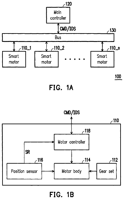
Auto-addressing smart motors
A way to assign ID codes to a chain of smart motors in sequence, so a multi-axis controller knows which is which.
US 9,780,589 B2 · Assignee: Ricoh Company, Ltd. · Inventors: Yoshida; Masaaki et al.
Sheet 1 of 21 from the published document. All sheets in the USPTO PDF
An electrical equipment is supplied with electric power from one of an electric power supply system and a secondary battery. The electrical equipment includes a switch circuit and a module. The switching circuit switches a power supply source for supplying electric power to the electrical equipment between the electric power supply system and the secondary battery. The module includes a processor to execute a program to perform a controlling process including a process of controlling the switch circuit to selectively connect the electrical equipment to one of the electric power supply system and the secondary battery according to a control signal supplied from an external device.
In recent years, a demand for power-saving has increased to solve environmental problems. It is considered as one of measures for solving the environmental problems to forcibly restrict electric power supply by an electric power supplier. In order to materialize such a power-saving scheme, air-conditioners and OA (Office Automation) devices provided with an electric power saving function have been commercialized. For example, there is an air-conditioner that automatically sets a so-called power-saving mode in which the air-conditioner is intermittently operated, when temperature and humidity reach predetermined setting values. In such an air-conditioner or OA device, a power-saving control is performed based on a setting value set for each device and a use condition of each device, and is performed under an individual control. Moreover, there is suggested a system in which electric power
8 of 21 drawing sheets so far from the published document, cropped to the drawing. Every sheet is in the USPTO PDF.
What the patent claimed, word for word. All of it is now free to use.
The present application is based upon and claims the benefit of priority of Japanese Patent Application No. 2013-188628, filed on Sep. 11, 2013, the entire contents of which are incorporated herein by reference.
The present invention generally relates to an electrical equipment and an electric power control system using a secondary battery.
In recent years, a demand for power-saving has increased to solve environmental problems. It is considered as one of measures for solving the environmental problems to forcibly restrict electric power supply by an electric power supplier.
In order to materialize such a power-saving scheme, air-conditioners and OA (Office Automation) devices provided with an electric power saving function have been commercialized. For example, there is an air-conditioner that automatically sets a so-called power-saving mode in which the air-conditioner is intermittently operated, when temperature and humidity reach predetermined setting values. In such an air-conditioner or OA device, a power-saving control is performed based on a setting value set for each device and a use condition of each device, and is performed under an individual control.
Moreover, there is suggested a system in which electric power sensors are provided to a house, an office, a plant, etc., to achieve so-called electric power visualization so as to improve power-saving awareness for people.
For example, Japanese Laid-Open Patent Application No. 2004-360925 discloses a power-saving control system that improves a power-saving efficiency. In the power-saving control system, illumination devices, air-conditioners and OA devices are integrally controlled based on detection data output from a first sensor for controlling the illumination devices, a second sensor for controlling the air-conditioners and a third sensor for controlling the OA devices.
The above-mentioned power-saving control system uses only one electric power supply system. Accordingly, this system cannot appropriately respond to a situation where the above-mentioned forcible power restriction or power stop occurs.
Moreover, the above-mentioned power-saving control system is capable of reducing a contract amount of electricity or a demand value (an average amount of electric power used for 30 minutes) if the energy-saving is progressed by the power-saving control system. However, this system does not provide a method or means for responding to a case where an actual amount of use of electricity exceeds a reduced contract amount of electricity or a reduced demand value. Therefore, it may be difficult for this system to achieve an effective power-saving control.
There is provided according to an aspect of the present invention an electrical equipment configured to be supplied with electric power from one of an electric power supply system and a secondary battery, the electrical equipment including: a switch circuit that switches a power supply source for supplying electric power to the electrical equipment between the electric power supply system and the secondary battery; and a module including a processor to execute a program to perform a controlling process including a process of controlling the switching circuit to selectively connect the electrical equipment to one of the electric power supply system and the secondary battery according to a control signal supplied from an external device.
There is provided according to another aspect of the present invention an electric power control system including: the electrical equipment; an electric power supplying part including the electric power supply system and the secondary battery; a plurality of electric devices that receive electric power from the electric power supplying part, the electric equipment serving as one of the electric devices; an environment sensor that detects physical amounts representing a condition of an environment of the electric power control system and outputs detection data; and an electric power control device that controls electric power supplied to the electric devices, wherein the electric power control device includes a computer that executes a program to perform an electric power controlling process including: collecting the detection data from the electric power sensor and the environment sensor and storing the collected detection data in a detection data storing part; storing control condition data in an electric power condition data storing part, the control condition data including information regarding a contract amount of electric power previously set and information regarding an accumulated amount of power consumption; storing control device data in a control target device data storing part, the control device data including device identification information for identifying each of the electric devices and priority order identification information for identifying a priority order given to each of the electric devices; determining which one of the electric power control system and the secondary battery is to supply electric power to the electric devices on an individual device basis based on information including the detection data, the control condition data and the control device data, and also determining an amount of electric power to be supplied to the electric devices on an individual device basis or determining whether to stop supplying electric power to the electric devices on an individual device basis; and sending an instruction to each of the modules to control corresponding one of the switch circuits in accordance with results of the aforementioned determinations.
Other objects, features and advantages of the present invention will become more apparent from the following detailed description when read in conjunction with the accompanying drawings.
The objects and advantages of the invention will be realized and attained by means of the elements and combinations particularly pointed out in the claims.
It is to be understood that both the foregoing general description and the following detailed description are exemplary and explanatory and not restrictive of the invention.
FIG. 1 is a diagram of an entire structure of an electric power control system according to a first embodiment;
FIG. 2 is a block diagram of the electric power control system;
FIG. 3 is an illustration of an outline structure of the secondary battery;
FIG. 4A is a block diagram of a power supply common module;
FIG. 4B is a block diagram of an AFE&CPU provided in the power supply common module;
FIG. 5A is a plan view of an intelligent tap;
FIG. 5B is a block diagram of a functional structure of the intelligent tap;
FIG. 5C is an front view of the intelligent tap;
FIG. 6A is a plan view of a power supply plug to be connected to the intelligent tap;
FIG. 6B is a front view of the intelligent tap;
FIG. 6C is a side view of the intelligent tap;
FIG. 6D is an illustration of the intelligent tap;
FIG. 7 is a block diagram of an electric circuit of the intelligent tap;
FIG. 8A is a side view of an example of an illumination device;
FIG. 8B is a side view of another example of the illumination device;
FIG. 9 is a side view of another example of the illumination device;
FIG. 10 is a side view of another example of the illumination device;
FIG. 11A is a side view of another example of the illumination device;
FIG. 11B is a side view of another example of the illumination device;
FIG. 12A is a side view of another example of the illumination device;
FIG. 12B is an enlarged plan view of a portion surrounded by a circle in FIG. 12A ;
FIG. 13A is a part of a flowchart of a monitoring process performed in the electric power control system;
FIG. 13B is a remaining part of the flowchart of the monitoring process performed in the electric power control system;
FIG. 14A is a part of a flowchart of a secondary battery and electric device controlling process performed in the electric power control system;
FIG. 14B is a remaining part of the flowchart of the secondary battery and electric device controlling process performed in the electric power control system;
FIG. 15 is an illustration of an outline of an electric power control system according to a second embodiment;
FIG. 16 is an illustration of an outline of an electric power control system according to a third embodiment;
FIG. 17 is an illustration of an outline of an electric power control system according to a fourth embodiment;
FIG. 18 is a flowchart of a reverse flow preventing controlling process according to the fourth embodiment;
FIG. 19 is an illustration of an outline of an electric power control system according to a fifth embodiment; and
FIG. 20 is an illustration of an outline of an electric power control system according to a sixth embodiment.
A description will now be given, with reference to the drawings, of embodiments of the present invention.
An electric power control system according an embodiment of the present invention is provided to a house, an office, a plant, etc., having a power supply system for supplying electricity and at least one secondary battery for supplying electricity.
In the following description and the attached drawings, equivalent members and parts are given the same reference numerals, and duplicate explanations will be omitted. Additionally, the drawings do not indicate a relative ratio between the members and parts, and specific dimensions and sizes of the members and parts can be determined by a person skilled in the art in light of the non-limiting embodiments mentioned below. First Embodiment
A description will be given, with reference to the drawings, of an electric power control system according to a first embodiment of the present invention.
First, a description is given, with reference to FIGS. 1 and 2 , of an entire structure of the electric power control system 1 , which uses a secondary battery, according to the first embodiment.
As illustrated in FIG. 1 , the electric power control system 1 includes an electric power supply system 2 and a secondary battery 3 as an electric power supplying part for supplying electricity to, for example, an office building. A plurality of the secondary batteries 3 may be provided in the electric power control system 1 . Although not illustrated in the figures, the electric power supply system 2 includes a wiring board, which is an electric power receiving terminal, and a distribution board.
1. The electric power control system 1 (hereinafter, may be referred to as the “power control system 1 ”) includes a plurality of electric devices 140 , each of which receives electricity from the electric power supplying part. The electric devices 140 includes, for example, an illumination equipment or device 4 , an air-conditioning equipment or device 5 , and an office equipment or device 6 (hereinafter, referred to as the “OA device 6 ”). The illumination equipment or device 4 is, for example, an LED lamp or light (hereinafter, may be referred to as the “LED lamp 4 ”). The air-conditioning equipment or device 5 is, for example, an air-conditioner. The office equipment 6 includes, for example, an MFP (multi-function peripheral) 61 , a personal computer 62 , a projector 63 , etc. Each of the electric devices 140 including the illumination equipment 4 , the air-conditioning equipment 5 and the OA device 6 is preferably provided with an electric power sensor (hereinafter, may be referred to as the “power sensor 7 ”) as illustrated in FIG. 2 . Additionally, each of the electric devices 140 including the illumination equipment 4 , the air-conditioning equipment 5 and the OA device 6 is preferably provided with an electric power supply common module (hereinafter may be simply referred to as the “common module 8 ” or the “module 8 ”), which is mentioned later in detail. In the figures, the electric power supply common module 8 is simply represented as “module”. The common module 8 is preferably incorporated in an intelligent-type power strip 9 (hereinafter referred to as the “intelligent tap 9 ”), which is a block of electrical sockets that attaches to the end of a flexible cable and allows multiple electrical devices to be plugged in. The intelligent tap 9 is an electrical equipment which generally has a plurality of receptacles into which plugs of electric devices can be inserted. The intelligent tap can be installed or placed near the electric devices 140 so as to supply electricity to the electric devices 140 . The intelligent tap 9 has a function of controlling the power supply to the electric devices 140 as mentioned later.
The electric devices 140 may include an electronic blackboard, an electric tea pot, an electric coffee pot, etc. Each of the electric devices 140 is not necessarily mounted with the power supply common module 8 .
The electric power control system 1 preferably includes environment detectors 7 . The environment detectors 7 include various sensors such as, for example, a human body sensor 71 , an illuminance sensor 72 , a temperature sensor 73 , a humidity sensor 74 , etc., which are necessary for an electric power supply control. For example, a CO.sub.2 sensor may be used as one of the environment detectors 7 . Each of the environment detectors 7 is preferably provided with the common module 8 .
The human body sensor 71 detects existence of a person in an office or the like by detecting an infrared ray emitted from a human body. The illuminance sensor 72 detects an illuminance inside an office or the like. The temperature sensor 73 detects a temperature inside an office or the like. The humidity sensor 74 detects humidity in an office or the like. Each of the environment detectors 7 preferably receives electricity supplied from a harvesting system and stores the received electricity in a battery 75 . The harvesting system is a system according to an environment generating technology to generate electricity by acquiring (harvesting) a minute energy from a surrounding environment such as a motion of a person and object (vibration, heat), a light, a radio-wave, a temperature, etc. Although the acquired electric power is as small as several microwatts (μW) to several tens milliwatts (mW), such a generating device according to the environment generating technology is excellent in portability, and does not require charge and battery replacement. Additionally, the generating device does not discharge CO.sub.2. Of course, the environment detectors 7 may be supplied with electricity from the electric power supply system 2 .
The electric power control system 1 includes an electric power control device 30 that controls supply of electricity to the electric devices 140 using detection data from the environment detectors 7 and the electric power sensor 70 .
The electric power control device 30 is connected to each of the electric devices 14 , the environment detectors 7 and the electric power sensor 70 via a network N so that the electric power control system 1 is capable of exchanging information with these devices and sensors.
The secondary battery 3 is provided with the electric power control device 30 as illustrated in FIG. 3 . Although the secondary battery 3 is illustrated as being separated by the electric power control device 30 into an upper portion and a lower portion in FIG. 3 , the electric power control device 3 is attached to a side of the secondary battery 3 and does not divide the secondary battery 3 . The secondary battery 3 includes an electric power switching device 37 that switches a supply source of electricity to the electric devices 140 between the electric power supply system 2 and the secondary battery 3 on an individual electric device basis. Additionally, the electric power control device 30 is provided with a display device 35 such as an LCD (Liquid Crystal Display). Information regarding an electric power control such as, for example, a remaining amount of battery power, a use condition and a usable time of each of the electric devices 140 may be preferably displayed on the display device 35 . Moreover, the electric power control device 30 may be provided with an input/output device 36 such as, for example, a keyboard, a printer, etc. The input/output device 36 is capable of rewriting data and programs stored in the electric power control device 30 and outputting the data and programs to external devices. The input/output device 37 is equipped with a remote access device with which data and programs sent from external devices are rewritable. Such a remote access is made in a case of accessing a management computer 31 via the Internet though, for example, a smartphone.
A description is given below, with reference FIG. 2 , of a structure of the electric power control device 30 .
The electric power control device 30 includes the management computer 31 as an example of a power controlling means, a detection data storing part 32 , an electric power condition data storing part 33 and a control target device data storing part 34 as an example of a control device data storing means. The management computer 31 has functions of a recording means, a controlling means including a means relating to an electric power control, a power computing means and a notifying means. A processor such as a CPU provided in the management computer 31 performs a process mentioned later by executing a power control program stored in a ROM. The management computer 31 controls each of the illumination device 4 , the air-conditioning device 5 and the OA device 6 according to the process mentioned later. The management computer 31 also includes a communication interface (I/F) to receive detection signals from the environment detectors 7 and the common module 8 (including the intelligent tap 9 ) and transmit control signals regarding the electric power control in order to perform various processes.
Moreover, the management computer 31 is connected with each of the data storing parts 32 , 33 and 34 so as to acquire data stored in the data storing parts 32 , 33 and 34 when performing various processes. For example, the management computer 31 performs a process of computing a usable time when each electric device 140 is continuously used and displaying the computed usable time on the display device 35 . Such a display is preferably performed especially when it is determined that a power supply from the electric power supply system 2 is interrupted.
The detection data storing part 32 stores detection data regarding a detection result of each of the environment detectors 7 and the electric power sensors 70 incorporated in the respective common modules 8 . The detection data contains, for example, data regarding a sensor identifier, a detection time and a detection result. Here, the sensor identifier is used to identify each of the sensors 70 to 74 . Different sensor identifiers are assigned to a plurality of sensors of the same kind, respectively. The detection data is data indicating a result of detection acquired by each of the environment detectors 7 and the electric power sensors 70 .
The electric power condition data storing part 33 stores previously determined control condition data. The control condition data is, for example, information regarding a demand value, a contract amount of electric power, an amount of power consumption, a total amount of power consumption and a remaining amount of battery power, information regarding planned power outage, and information regarding electricity interruption from the electric power supply system 2 .
The demand value indicates an amount of power consumption in a time span during which a maximum amount of electric power is consumed when viewing a temporal transmission of an amount of power consumption on a monthly or yearly basis.
The contracted amount of power consumption is a value of an amount of power consumption contracted with a power company. The total amount of power consumption is a value obtained by simply summing amounts of power consumed in each period such as one day, one week or one month. In this connection, previous data such as, for example, the total amount of power consumption for a past one week is recorded.
The information regarding planned power outage is data regarding time and date of carrying out a power outage when the power outage is announced previously. The information regarding interruption of power supply from a power system is power interruption information previously announced by a power company, and is data regarding time and date of interrupting power supply. Additionally, the power interruption information may include information regarding a demand response, which has been promoted in recent years. The demand response is a system to promote suppression of power consumption and attempt cooperation of supply and reception of electric power by a supplier setting various charge setting in controlling supply and reception of electricity such as, for example, increasing an electricity charge for a peak time and paying an incentive to appropriate power saving. Accordingly, by performing a control responding to the demand response information, a more effective power saving including cost saving can be achieved.
The control target device data storing part 34 stores control device data. The control device data includes, for example, device identification information for identifying each of the electric devices 140 and priority order information for identifying a priority order of controlling the power supply to the electric devices 140 .
The device identification information includes identifiers for identifying each of the plurality of illumination devices 4 , a plurality of air-conditioning devices 5 and a plurality of OA devices 6 (MPFs 61 , personal computers 62 and projectors 63 ) that are controlling targets. Additionally, the device identification information preferably includes information regarding properties of electric devices such as power consumption and maximum rating of each device.
The priority order information includes flag information regarding a condition of controlling power supply. Especially, the priority order information is used when electric power consumption becomes equal to or exceeds a power reference value or it is necessary to temporarily reduce a power supply amount. The priority order information is set in four steps, “A” and “1” to “3” in the present embodiment so that electric power is supplied preferentially if the priority order flag is a numerical value and the value is smaller, and an electric power supplied is restricted if the value is larger.
An electric device given the priority order flag being set to “A” is a device set in an automatic mode according to which the electric device is mandatorily controlled by the electric power control of the electric power control device 30 . Accordingly, the priority order flag “A” is set to an electric device to which a power can be supplied appropriately in conformity with a current condition. The priority order “1” indicates to supply an electric power always preferentially. The priority order “2” indicates to supply an electric power only at a normal time or a power reducing time, and to stop an electric power supply when an interruption of power supply from the electric power supply system 2 occurs. The priority order “3” indicates to supply an electric power only at a normal time, and to permit an electric power supply to stop at a power reducing time.
In the present embodiment, a priority order (flag) is previously given to each of the electric devices 140 . The priority order can be changed by using the input/output device 36 of the electric power control system 1 . Additionally, as mentioned later, a user can manually change the priority order by operating priority order setting parts 97 provided in the intelligent tap 9 .
In the present embodiment, an appropriate priority order (flag) is set to each of the illumination devices 4 , the air-conditioning devices 5 and the OA devices 6 and the electric power control is performed on an individual device basis. Accordingly, an optimum electric power control can be achieved more effectively without failing a comfort of individuals as compared to a power saving method in which a priority is simply given to, for example, all of the air-conditioning devices 5 when a power supply to some of the devices is to be stopped.
The control target device data storing part 34 also stores information regarding which electric power supply part is to be connected to each of the electric devices 140 . Each of the electric devices 140 illustrated in FIGS. 1 and 2 is provided with an electric power supplying means, which is connectable to either one of the electric power supply system 2 and the secondary battery 3 . However, there may be a case where an electric power supplying means is not provided because the electric power supplying means may be provided in the intelligent tap 9 or the illumination device 4 as mentioned later.
A description will now be given, with reference to FIG. 4A , of the electric power supply common module 8 incorporated in each of the electric devices 140 .
As illustrated in FIG. 4A , the electric power supply common module 8 includes the electric power sensor 70 , an AC/DC converter (direct current stabilizing power supply) 80 , an AFE&CPU 81 and a radiofrequency I/F 82 . AFE (Analog Front End) is an analog circuit for connecting a sensor to a digital signal processing device such as a microcomputer including a CPU (Central Processing Unit). The CPU of the AFE&CPU 81 serves as a controlling means for controlling a supply of electric power to a target electric device. The AFE&CPU 81 is generally configured by a microcomputer including a CPU, a ROM, a RAM, etc., as illustrated in FIG. 4B . The radiofrequency I/F 82 is a communication interface, which preferably uses a radiofrequency communication protocol such as ZigBee to transmit data.
If the electric power supply common module 8 (control circuit) is incorporated in each of the electric devices 140 , there is no need to construct a large-scale device control system, which requires a large scale construction in a house, an office building, a plant facility, etc. Additionally, the electric power control device 30 can be configured to be capable of adjusting an amount of electric supply for each of the electric devices 140 , which contributes to an optimum power control which does not deteriorate a comfort of individuals. The electric power supply common module 8 may be incorporated into or attached to each of the electric devices 140 .
The electric power supply common module 8 may be incorporated into the intelligent tap 9 , which is a example of a power supply tap illustrated in FIGS. 5A to 5C .
The intelligent tap 9 includes one or more power supply sockets (receptacles) 90 . The intelligent tap 9 is configured to collectively perform power supply controls for a plurality of electric devices 140 connected to the power supply sockets 90 . The power supply control described hereinafter includes a function to send information regarding power consumption of each of the connected electric devices to the electric power control device 30 and executes instructions sent from the electric power control device 30 .
The intelligent tap 9 includes a sensor module 900 , which includes the electric power sensor 70 and an AFE&CPU 91 , for each of the power supply sockets 90 . Additionally, the intelligent tap 9 is preferably configured to include an electric power supply common module 901 , which includes an AFE&CPU 92 , a radiofrequency I/F 93 , an AC/DC converter 94 , a relay controller 95 and a switch circuit 96 . The switch circuit 96 is an example of a switching means for switching connection to the electric power supply part. It should be noted that the AFE&CPU 91 and the AFE&CPU 92 have the same configuration as the AFE&CPU 81 mentioned above.
The switch circuit 96 is a relay circuit (refer to FIG. 7 ) for switching the electric power supply part to which each of the sockets 90 is connected between the electric power supply system 2 and the secondary battery 3 in order to supply electric power from either one of the electric power supply system 2 and the secondary battery 3 to each of the electric devices connected to the power supply sockets 90 of the intelligent tap 90 .
The intelligent tap 9 is connected with a plurality of electric devices such as, for example, the MFP 61 , the personal computer 62 and the projector 63 . The intelligent tap 9 reduces or cuts off a waiting time power consumption of each of the electric devices by operating the switch circuit 96 by a relay controller 95 according to an instruction or command sent from the AFE&CPU 92 . Additionally, the intelligent tap 90 is capable of performing power supply control by the electric power control device 30 such as an ON/OFF switching control and a remote control of each device according to power measurement information of each device sent from each sensor module 900 .
The intelligent tap 9 is provided with the priority order setting parts 97 as a priority order setting means for setting a priority for restriction of electric power supply by manual operation of a user. The priority order setting parts 97 provide an advantage in that an appropriate power supply control can be performed for each of the electric devices connected to the intelligent tap 9 in each situation, especially when the power supply by the electric power supply system 2 is interrupted or when a large restriction of electric power supply is required such as in a time of planned power outage.
In the present embodiment, each of the priority order setting parts 97 is a dial-type input part as illustrated in FIGS. 5A and 5C . It is preferable to display a priority order, which is set by the corresponding priority order setting part 97 , on a display part 97 a . If the priority order is set manually by a user, the radiofrequency I/F 93 of the electric power common module 901 transmits a change signal to the electric power control device 30 . Then, the management computer 31 of the electric power control device 30 changes or rewrites the priority order information of the corresponding electric device stored in the control target device data storing part 34 .
The representation of the priority order preferably includes, for example, the levels “A” and “1” to “3” as mentioned above, and a description of the priority order will be omitted.
The intelligent tap 9 preferably includes device recognizing parts 98 (refer to FIG. 5A ) for recognizing each of the electric devices 140 connected to the intelligent tap 9 . Each of the device recognizing parts 98 is provided at a corresponding one of the power supply sockets 90 . That is, each of the device recognizing parts 98 is configured to acquire the device information according to the relationship with a connection plug (a power supply plug) of each of the electric devices illustrated in FIGS. 6A through 6D , which is inserted into and connected to one of the power supply sockets 90 .
The connection plug 10 includes, as illustrated in FIG. 6A , a pair of plug blades 101 protruding from a body of the connection plug 10 and a storing part 102 provided inside the body of the connection plug 10 . The storing part 102 stores the device identification information of the electric device, which receives electric power through the pair of plug blades 101 of each of the electric devices 140 , and the priority order information of each of the electric devices 140 . Additionally, as illustrated in FIG. 6C , a power cable 103 and a communication cable 104 extend from the body of the connection plug 10 . The power cable 103 and the communication cable 104 are connected to the corresponding one of the electric devices 140 .
The storing part 102 is a semiconductor memory or the like, and includes a USB terminal 102 a (plug type). The USB terminal 102 a is attached to the same surface of the body of the connection plug 10 as the surface from which the pair of plug blades 101 protrude.
On the other hand, the device recognizing terminal 98 has a USB terminal (socket type), which is connectable with the USB terminal of the storing part 102 . When connecting the connection plug 10 to the intelligent tap 9 , the plug blades 101 are inserted into the power supply socket 90 and the USB terminal 102 a of the connection plug 10 is simultaneously inserted into the device recognition part 98 of the intelligent-type tap 90 . Accordingly, after the intelligent tap 90 is connected to one of the electric devices 140 through connection plug 10 , the device recognition terminal 98 of the intelligent tap 90 acquires the device identification information of the connected electric device stored in the storing part 102 of the connected electric device. Then, the intelligent-type tap 9 transmits the acquired device identification information of the connected electric device to the management computer 31 of the electric power control device 30 through the radiofrequency I/F 93 . The management computer 31 stores the received identification information in the control target device data controlling part 34 . Accordingly, the electric power control device 30 is capable of identifying the electric device connected to the intelligent-type tap 9 .
The exchange of the device identification information mentioned above is not limited to the above-mentioned configuration. Each of the electric devices 140 , which are not connected to the intelligent tap 9 , may be configured to transit the device identification information to the electric power control device 30 (the management computer 31 ) by mounting a radiofrequency I/F beside the storing part 102 in the connection plug of the electric device. Alternatively, the device identification information may be transmitted to the electric power control device 30 (the management computer 31 ) through the communication cable 104 .
FIG. 7 illustrates a connection relationship between the intelligent tap 9 , the connection plugs 10 and the electric devices 140 . Although the MFP 61 , the projector 63 and the two personal computers 62 are connected to the intelligent tap 9 in the example of FIG. 7 , the electric devices 140 connected to the intelligent tap 9 are not limited to the MFP 61 , the projector 63 and the two personal computers 62 .
Each of the electric devices 140 is provided with the connection plug 10 , which stores its own device identification, and the connection plug 10 is connected to one of the power supply sockets 90 of the intelligent tap 9 . The intelligent tap 9 acquires the device identification information of the particular electric device 140 from the storing part 102 of the connection plug 10 of the particular electric device 140 , and transmits the acquired identification information to the electric power control device 30 by the radiofrequency I/F 93 .
The electric power control device 30 determines whether to connect each of the electric devices 140 connected to the intelligent tap 9 to the electric power supply system 2 or the secondary battery 3 on an individual device basis. The electric control device 30 determines an amount of electric power to be supplied or whether to stop the supply of electric power, and transmits a power control signal, which is information of a result of the determination, to the intelligent tap 9 through the communication I/F. Then, the power supply common module 901 of the intelligent tap 9 performs a power controlling process by the electric power control device 30 . That is, the relay controller 95 controls the switch circuit 96 so that electric power is supplied from one of the electric power supply part determined by the electric power control device 30 to the corresponding electric device 140 . The relay controller 95 is configured to be capable of controlling the switch circuit if the switch circuit is of a three-contact type.
The detection data output by the electric power sensor 70 of the sensor module 900 is transmitted by the radiofrequency I/F 93 to the electric power control device 30 as information indicating an amount of power consumption of each of the connected electric devices 140 which consume electric power to operate.
A description is given below, with reference to FIGS. 8A through 12B , of a configuration of the illumination device 4 according to the present embodiment. The illumination device 4 is an electrical equipment generally attached to a ceiling or a side wall of a room in order to illuminate inside the room.
FIG. 8A illustrates a normal straight-tube type LED lamp as an example of the illumination device 4 attached to a ceiling. FIG. 8B illustrates a straight-tube type LED lamp as an example of the illumination device 4 according to the present embodiment. Hereinafter, the illumination device 4 according to the present embodiment may be referred to as the “LED lamp 4 ”. Although the illumination device 4 according to the present embodiment may be a straight-tube type LED (Light Emitting Diode) lamp, which is directly attached to a ceiling as illustrated in FIGS. 8A and 8B , the illumination device 4 is not limited to such a straight-tube LED lamp directly attached to a ceiling.
The LED lamp 4 illustrated in FIG. 8B includes an externally-attaching adaptor 12 having a pair of adapter members 120 , which are used to attach the LED tube 4 a to a lamp holder including a pair of attachment members 11 attached to a ceiling. The attachment members 11 forming the lamp holder may be included in the LED lamp 4 serving as an electrical equipment. As illustrated in FIG. 8B , one of the adapter members 120 incorporates the electric power supply common module 8 therein.
In order to perform an electric power control for a plurality of the LED lamps 4 on an individual lamp basis, the electric power supply common module 8 is incorporated into each of the LED lamps 4 . However, if LED lamps have already been installed, the installed LED lamps must be replaced by the LED lamps 4 in order to perform the electric power control according to the present embodiment, which requires additional investment costs. Thus, by using the LED lamp 4 including the adapter member 120 in which the electric power supply module 8 is incorporated, the electric power control system 1 effectively using the existing equipment can be materialized.
The externally-attaching adaptor 12 includes the pair of adaptor members 12 each of which is formed in a crank shape (bent into the shape of a crank). The above-mentioned common module 8 is incorporated in one of the adaptor members 120 . Although not illustrated in the figures, each of the adaptor members 120 has two electricity receiving terminals on an outer surface of an upper portion, which are used to receive electricity from the corresponding attachment member 11 , and two electricity supplying terminals on an outer surface of a lower portion, which are used to supply electricity to the LED tube 4 a of the LED lamp 4 .
Generally, a pair of attachment members 11 , which support respective opposite ends of the straight-tube type LED tube 4 a of the LED lamp 4 , have already been attached to a ceiling. Each of the attachment members 11 is provided with two power-supply and support terminals on an inner surface facing an end of the LED tube 4 a of the LED lamp 4 in order to support the LED tube 4 a and supply electricity to the LED tube 4 a.
The description continues in the full USPTO document.
About 6,605 words. The USPTO PDF has it with every drawing.
Fees are due 3.5, 7.5 and 11.5 years after grant. This patent expired on October 3, 2025, so the fee marked "not paid" was the one that went unpaid.
ELECTRICAL EQUIPMENT AND ELECTRIC POWER CONTROL SYSTEM
Filed Sep 2014 · published Mar 2015Electric power control system
Filed Sep 2014 · granted Oct 2017Earlier publications, parents and continuations. None of them can still be enforced, or this patent would not be listed.
Prior art cited by the examiner or applicant. Useful when you check your own idea for novelty.
Everything on this page comes from the documents linked above.


