Lapsed, fee not paid9 drawings
AI & Machine Learning · US 9,774,743 B2
Silence signatures of audio signals
A method performed by a processing system.
US 9,778,762 B2 · Assignee: FUJIFILM CORPORATION · Inventors: Yamamoto; Akira et al.
Sheet 1 of 6 from the published document. All sheets in the USPTO PDF
The information processor includes an input unit having an illuminating part and an image pickup part, and an input medium having an input surface on which inputting of information is carried out by the input unit which has position coordinates on the input surface coded by a dot pattern. The input unit irradiates light from the illuminating part onto input surface of the input medium. The irradiated light reflects off the dot contained in the dot pattern which is picked up by the image pickup part, and position information of the dot pattern is obtained. The input unit further has an input unit angular position measuring part that measures an angular position of the input unit when the light is irradiated. Based on corrected position information obtained by correction processing based on the angular position, input information, that is specified by the position coordinates is obtained.
Field of the Invention The present invention relates to an information processor and to a method of inputting information to this information processor. Discussion of the Background In recent years, information processors have been proposed where an input unit such as an electronic pen is displaced on an input surface having a dot pattern and the displacement path is obtained as electronic information based on the position coordinates of each position on the input surface (for example, see Patent References 1 and 2). Patent Reference 1: Japanese Patent No. 4,973,248 Patent Reference 2: JP-A-No. 2014-67398 SUMMARY OF THE INVENTION With the information processors proposed in Patent References 1 and 2 above and the like, for example, a handwritten text or image can be obtained as electronic information that can be processed and stored electronically by a computer. To make this possible, the
All 6 drawing sheets from the published document, cropped to the drawing.
What the patent claimed, word for word. All of it is now free to use.
This application claims priority under 35 U.S.C 119 to Japanese Patent Application No. 2014-223349 filed on Oct. 31, 2014. The above application is hereby expressly incorporated by reference, in its entirety.
Field of the Invention
The present invention relates to an information processor and to a method of inputting information to this information processor.
Discussion of the Background
In recent years, information processors have been proposed where an input unit such as an electronic pen is displaced on an input surface having a dot pattern and the displacement path is obtained as electronic information based on the position coordinates of each position on the input surface (for example, see Patent References 1 and 2).
Patent Reference 1: Japanese Patent No. 4,973,248
Patent Reference 2: JP-A-No. 2014-67398 SUMMARY OF THE INVENTION
With the information processors proposed in Patent References 1 and 2 above and the like, for example, a handwritten text or image can be obtained as electronic information that can be processed and stored electronically by a computer. To make this possible, the position coordinates of various positions on an input surface are coded by a dot pattern (coding by a dot pattern). More specifically, each position on the input surface is coded so that each of the position coordinates is specified by a dot pattern comprised by some combination of multiple dots.
For example, Patent Reference 1 discloses (for example, see paragraph 0009 in Patent Reference 1) obtaining the position information of an input unit by forming a dot pattern for coding position coordinates out of a nonvisible light reflecting material and reading the reflection pattern of the nonvisible light to specify the displacement path of the input unit (described as an input terminal in Patent Reference 1). Additionally, Patent Reference 2 discloses detecting a dot pattern by absorbing, in dots, infrared light that is emitted by an input unit (described as an electronic pen in Patent Reference 2) and reflecting the infrared light in areas outside the dots (for example, see paragraphs 0031 to 0037 in Patent Reference 2).
In the above information processors, electronic information in the form of the displacement path of an input unit can be obtained by specifying the position on an input surface on which the input unit has passed when being displaced based on position coordinates specified based on a dot pattern that is detected by the reflection of light or the like. Normally, the input unit is equipped with an illuminating part and an image pickup part. The illuminating part irradiates light toward the dot pattern and the image pickup part uses the reflected light or the like obtained by light reflecting off dots to detect a dot pattern.
However, based on investigation, the present inventors found that in the above information processors, there were cases where reading errors ended up occurring without being able to specify the position coordinates of the positions on which the input unit had passed on the input surface. Such reading errors may cause partial loss, distortion, and the like in text and images obtained as electronic information. Thus, reproducibility ended up dropping in the course of reproducing the text and images drawn by the input unit as electronic information.
With the above information processor, it becomes possible not only to obtain the displacement path of the input unit as electronic information, but also to specify the position of virtual buttons indicated (selected) by means of the input unit in an input medium (such as an information processing terminal in the form of a tablet terminal or the like) having virtual buttons for the selection of one or more among multiple selection options. However, when a reading error ends up occurring such that the position indicated by the input unit cannot be specified, it becomes impossible to identify and specify the virtual button that has been selected by means of the input unit.
Accordingly, in information processors utilizing coding by dot patterns, there is a need to enhance the precision with which position coordinates are specified.
Thus, an aspect of the present invention provides for means for enhancing the precision with which position coordinates are specified in an information processor that specifies position coordinates utilizing coding by dot patterns.
An aspect of the present invention relates to an information processor,
which comprises:
an input unit having an illuminating part and an image pickup part and
an input medium having an input surface on which inputting of information is carried out by the input unit;
wherein, on the input medium, position coordinates on the input surface are coded by a dot pattern present on the input medium,
the dot pattern contains one or more dots exhibiting retroreflectivity for light entering from a direction oblique to the dot,
the input unit irradiates light from the illuminating part onto the input medium on the input surface of the input medium, the irradiated light reflects off the dot contained in the dot pattern, the reflected light is picked up by the image pickup part, and position information of the dot pattern containing the dot that has reflected light is obtained,
the input unit further has an input unit angular position measuring part that measures an angular position of the input unit during the light is irradiated, and
based on correction processed position information obtained by correction processing based on the angular position measured by the input unit angular position measuring part in the position information obtained, input information specified by the position coordinates of a position on the input surface on which the light is irradiated is obtained.
In the present invention and in the present specification, the term “dot” refers to a protruding portion having a shape in the form of a partially cut away sphere (partial spherical shape) or a shape in the form of a partially cut away spheroid (partial spheroidal shape). The dot appears as a circle when observed in a vertical direction. The center of the circle thus observed will be referred to as the dot center. The position of the dot center will be considered to be the dot center position in the present specification and in the present invention. The “dot diameter” refers to the diameter of the circle thus observed. The shape of the circle observed can be a perfect circle or can be an approximate circle such as an ellipse. Taking the position of maximum height in the vertical direction from the surface on which the dots are disposed (called the “apex” hereinafter) as 0°, taking the horizontal direction of the surface on which the dots are disposed as 90°, light entering toward the dot from a direction of greater than 0° but not greater than 50° will be referred to as “light entering from a direction oblique to the dot”.
Light reflection can be roughly divided into the three types of mirror surface reflection (positive reflection) where the incidence angle and reflection angle are equal, diffuse reflection (scattered reflection) where the light reflects in various directions, and retroreflectivity, where the reflecting light exits in the direction of incidence. An actual reflecting body will normally not just have complete mirror surface reflection, complete diffuse reflection, or complete retroreflectivity, but rather a reflectance distribution combining two or more of these properties. In the present specification and in the present invention, the term “retroreflectivity” refers to light reflecting back and exiting in the direction of incidence of the light, but mirror surface reflection can also be present. The term “direction of incidence of the light” means the precise angle or direction or with an error of less than ±10° from the precise angle or direction. The error from the precise angle or direction is desirably less than 5°, and preferably less than 3°. The dots constituting the dot pattern in the input medium desirably exhibit retroreflectivity at the dot apex, as well.
The presumptions of the present inventors that are given below are not intended to limit the present invention in any way. For example, dots employing a liquid crystal material having a cholesteric structure such as are described in Patent Reference 1 will normally exhibit retroreflectivity at the dot apex, but will not exhibit retroreflectivity for light entering from a direction oblique to the dot. Thus, with the dot pattern that is described in Patent Reference 1, when the input unit is tilted obliquely for use, strong reflected light cannot be achieved. As a result, coding by the dot pattern is precluded and a reading error ends up being generated. The present inventors presume the specific reason for this to be as follows.
Since a liquid crystal material having a cholesteric structure has the property of reflecting light most powerfully in the direction of the cholesteric helical axis (also referred to simply as the “helical axis” hereinafter), it can exhibit retroreflectivity for light entering in the direction of the helical axis. Additionally, the helical axis of a cholesteric structure will normally be aligned perpendicularly to the surface on which the cholesteric structure is disposed. For dots employing a liquid crystal material having a cholesteric structure, light perpendicularly entering the dot apex will retroreflect because it is entering in the direction of the helical axis. However, light entering from an oblique direction will not retroreflect because it is entering from a different direction than the direction of the helical axis, and is thought to diffusely reflect. Due to this diffuse reflection, the reflected light received by the input unit will be much weaker than the retroreflected light. Thus, it is normally impossible for the image pickup part of the input unit to generate an image and obtain reflected light of an intensity permitting detection of the dots. This is presumed to be why a reading error ends up being generated when employing an input unit that is tilted obliquely with dots utilizing a liquid crystal material having a cholesteric structure such as are described in Patent Reference 1.
By contrast, when the dots constituting the dot pattern are dots exhibiting retroreflectivity for light entering in a direction oblique to the dot, since retroreflected light can be obtained even when the input unit is obliquely tilted for use, it becomes possible for the image pickup part to generate an image and detect the dots.
However, investigation by the present inventors revealed that reading errors sometimes still ended up being generated even in an information processor utilizing dots that exhibited retroreflectivity for light entering in directions oblique to the dots such as set forth above. The present inventors conducted intensive research to determine why. As a result, they presumed the reason to be the following phenomenon unique to dots exhibiting retroreflectivity of light entering in an oblique direction.
In an information processor utilizing coding by dot patterns, the individual dots constituting a dot pattern are normally correlated to prescribed values based on the positions at which they are present on the input surface. For example, prescribed values (such as the numbers 0, 1, 2, 3) are correlated with individual dots by shifting the positions of the dots up, down, left, or right from a reference position (point of intersection of a vertical axis and horizontal axis forming a grid) on a virtual grid. Each position on the grid can be converted to a first bit value X coordinate and a second bit value Y coordinate. The dot pattern position information is comprised by combining the information thus correlated. Here, the position of each dot is specified as the dot center position, that is, the position of the center of the circle when observed vertically. The dot position coordinates (the position coordinates of a dot are not position coordinates specifying the individual position on the input surface, but rather position coordinates specifying the position at which the dot is disposed in order to identify individual dots) are normally specified by two-dimensional coordinates in the X direction and Y direction (horizontal axis and vertical axis). In the image that is generated by the image pickup part of the input unit, detected dots are identified based on the position coordinates of the brightest high point (center of brightness). More specifically, dots that are detected as an image by the image pickup part are identified as being dots that are disposed at the position coordinates of centers of brightness.
However, the above presumes that retroreflected light can be obtained from the dot apex using the input unit without tilting it. That is, there is a presumption that the dot centers and the brightness centers can be matched up.
When the input unit is used while tilted, the light that is irradiated by the illuminating part of the input unit enters obliquely with respect to the dots and retroreflects. However, in the retroreflected light thus obtained, the brightness is greatest at positions where the light entering the dot surface enters at an incidence angle that is perpendicular or nearly perpendicular. Accordingly, the brightness centers in the image generated by the image pickup part of the input unit do not match up with the dot centers (apexes). That is, there is a misalignment of the brightness center and the dot center. As a result, when a determination ends up being made that no dot having position coordinates that match those of the detected dot exists, a phenomenon whereby the dot cannot be identified ends up occurring. The present inventors presume that the reading error in information processors utilizing dots exhibiting retroreflectivity for light entering from directions oblique to the dots is produced by this phenomenon.
Accordingly, the present inventors conducted further extensive research. As a result, they corrected the misalignment of the positions of the brightness center and the dot center based on the angular position of the input unit when light was being irradiated by the illuminating part of the input unit on the input surface of the input medium. They discovered that this correction processing made it possible to identify dots even when the input unit was employed with a tilt. An information processor according to an aspect of the present invention was devised. The input unit of the information processor was equipped with an input unit angular position measuring part to effect this correction. In the present specification and in the present invention, the term “angular position” refers to a position that is specified by the angle relative to a reference surface or reference direction. Details regarding the input unit angular position measuring part and the correction processing will be given further below.
The above contains presumptions made by the present inventors and is not intended to limit the present invention in any way.
In one embodiment, the input unit is displaced on the input surface of the input medium while irradiating light onto the medium from the illuminating part. Based on correction processed position information, the input unit obtains input information in the form of the displacement path of displacement of the input unit on the input surface of the input medium.
In one embodiment, the dot is a cholesteric liquid crystal dot. The term “cholesteric liquid crystal dot” refers to a dot of a liquid crystal material having a cholesteric structure.
In one embodiment, the information processor comprises an input medium angular position measuring part that measures the angular position of the input medium. Based on the angular position of the input medium during light irradiation that is measured by the input medium angular position measuring part, the angular position of the input medium measured by the input medium angular position measuring part is corrected. Based on the corrected angular position, correction processed position information is obtained.
In one embodiment, the input medium has one or more additional layers provided on the dot pattern. Correction processing is conducted based on the refractive index and thickness of the additional layers and correction processed position information is obtained.
In one embodiment, the light that is irradiated by the illuminating part of the input unit is near infrared light. In the present invention and in the present spcification, the term “near infrared light” refers to electromagnetic waves within the wavelength range of 780 to 2,500 nm.
In one embodiment, the input unit is in the form of a pen.
In one embodiment, the input unit is a handwriting input pen.
In one embodiment, the input unit further comprises an information transmitting part that transmits the input information that is obtained to an information displaying part that displays the information.
A further aspect of the present invention relates to a method of inputting information to the above information processor, comprising irradiating light from the illuminating part onto the input medium on the input surface of the medium with the input unit in a tilted state relative to the input medium.
In one embodiment, the above method of inputting information comprises displacing the input unit while irirradiating light from the illuminating part onto the input medium on the input surface of the medium with the input unit in a tilted state relative to the input medium. In one embodiment, the information that is inputted in this manner is at least one selected from the group consisting of text information and image information.
An aspect of the present invention can provide an information processor utilizing coding by dot patterns that makes it possible to specify position coordinates with high precision even when using the input unit with a tilt relative to the input medium.
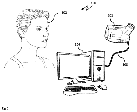
FIG. 1 is a descriptive drawing showing the schematic structure of a handwriting input pen in an embodiment of the input unit.
FIG. 2 is a descriptive drawing of the position misalignment of the brightness center and dot center.
FIG. 3 is a descriptive drawing showing specifically how correction processing is conducted.
FIG. 4 is a schematic sectional view of a dot the image of which is being picked up by the image pickup part of the input unit.
FIG. 5 is a descriptive drawing showing specifically how correction processing is conducted when another layer is present over the pattern layer.
FIG. 6 shows an example of flowcharts of specific implementation modes of conducting correction processing and obtaining input information.
FIG. 7 shows a sectional image, taken by a scanning electron microscope, of cholesteric liquid crystal dots fabricated in Examples.
The present invention is described below based on representative implementation modes. However, the present invention is not limited to such implementation modes. In the present specification and in the present invention, a numeric range denoted using the word “to” signifies a range including the preceding and succeeding numeric values as minimum and maximum values, respectively. Further, in the present specification and in the present invention, description relating to angles such as “vertical” and description relating to directions include the range of error that is accepted in the field of art to which the present invention belongs. For example, it means within a range of less than ±10° from the precise angle or direction. The error with the precise angle or direction is desirably less than or equal to 5°, preferably less than or equal to 3°.
[Information Processor]
An aspect of the present invention relates to an information processor, which comprises:
an input unit having an illuminating part and an image pickup part and
an input medium having an input surface on which inputting of information is carried out by the input unit;
wherein, on the input medium, position coordinates on the input surface are coded by a dot pattern present on the input medium,
the dot pattern contains one or more dots exhibiting retroreflectivity for light entering from a direction oblique to the dot,
the input unit irradiates light from the illuminating part onto the input medium on the input surface of the input medium, the irradiated light reflects off the dot contained in the dot pattern, the reflected light is picked up by the image pickup part, and position information of the dot pattern containing the dot that has reflected light is obtained,
the input unit further has an input unit angular position measuring part that measures an angular position of the input unit during the light is irradiated, and
based on correction processed position information obtained by correction processing based on the angular position measured by the input unit angular position measuring part in the position information obtained, input information specified by the position coordinates of a position on the input surface on which the light is irradiated is obtained.
The above information processor will be described in greater detail below.
<Input Medium>
The information processor is capable of inputting various information. For example, in one embodiment, the displacement path of displacement of the tip portion of the input unit on the input surface of the input medium can be obtained in the form of input information selected from the group consisting of text information and image information. In this manner, for example, it becomes possible to convert information inputted by handwriting to electronic information. In another embodiment, as set forth above, a virtual button selected by the input unit can be specified.
Since information processing is possible in the manner set forth above, the input medium has dot patterns. The dot patterns include dot patterns constituted by some combination of multiple dots. A summary of the coding of such dot patterns has been set forth above. Specific forms will be given below. When light is irradiated by the illuminating part of the input unit onto the input surface of the input medium on which such a dot pattern is present, the position on the input surface selected by the input unit can be specified based on the position information of the dot pattern that has reflected the light that has been irradiated. Thus, for example, a text or image that has been drawn in the form of the displacement path of the tip portion of the input medium can be obtained as electronic information. Further, the specification of virtual button as set forth above also becomes possible. The information processors and systems that utilize such dot patterns are known. For example, reference can be made to known art such as Japanese Patent Nos. 4,658,427, 4,138,658, and 4,973,248; and JP-A-Nos. 2014-67398 and 2012-230603.
In an information processor according to an aspect of the present invention, the dot pattern contains dots exhibiting retroreflectivity for light entering in a direction oblique to the dots. As stated above, the present inventors presume that this relates to the fact that it is possible to identify the dots and enhance the specification precision of position coordinates even in cases when the input unit is used with a tilt. It is optimal for all of the dots contained in the dot pattern to exhibit retroreflectivity for light entering in a direction oblique to the dots. However, the range of error that is accepted in the field of art to which the invention belongs—for example, embodiments in which fewer than or equal to 5% of the dots, based on the number of dots, do not have the above retroreflectivity—is included in one embodiment of the present invention. Neither the dot size (dot diameter), spacing between dots (distance between dots on center), nor the number of dots disposed on the input surface is specifically limited. These can be set based on the application of the information processor.
The material employed to form the dots can be any organic material or inorganic material, without limitation, so long as it permits the formation of dots exhibiting retroreflectivity for light entering in a direction oblique to the dots. A combination of an inorganic material and an organic material can also be used to form the dots. One example is the retroreflective material described in JP-A-No. 2008-268585, paragraphs 0010 to 0013.
From the perspective of further enhancing precision in specifying position coordinates, the dots desirably have wavelength-selective reflectivity. In the present invention and in the present specification, the term “wavelength-selective reflectivity” refers to the property of strongly reflecting light in a specific wavelength band. The dots exhibiting wavelength-specific reflectivity and retroreflectivity are desirably cholesteric liquid crystal dots.
(Cholesteric Liquid Crystal Dot)
Cholesteric liquid crystal dots will be described in greater detail below.
The wavelength-selective reflectivity of cholesteric liquid crystal dots is imparted by their cholesteric structure. The center wavelength λ of the wavelengths exhibiting wavelength-selective selectivity (the selective reflectivity wavelengths) depends on the pitch P (=helical pitch) of the helical structure in the cholesteric structure, and follows a relation with the average refractive index n of the cholesteric liquid crystal, with λ=n×P. Thus, adjusting the pitch of the helical structure permits adjusting the selective reflectivity wavelength. The pitch of the cholesteric structure normally depends on the type or concentration of added chiral agents, described further below. It is possible to achieve a desired pitch by adjusting them. A detailed description is given on pp. 60 to 63 of Fujifilm Research Report No. 50 (2005). The helical twist direction and pitch can be measured by the methods described in An Introduction to Experiments in Liquid Crystal Chemistry , compiled by the Japan Liquid Crystal Association, Sigma Publications, published in 2007, p. 46, and the Liquid Crystal Handbook, Liquid Crystal Handbook Compilation Committee, Maruzen, p. 196.
The cholesteric liquid crystal dots create a fringe pattern of bright and dark portions in the sectional SEM image of dots obtained by a scanning electron microscope (SEM). The repeating double portions of bright and dark portions (two bright portions and two dark portions) correspond to a single portion of the helical pitch. Accordingly, the pitch can be measured from the sectional SEM image. The direction normal to the various lines of the fringe pattern becomes the helical axis direction. The term “sectional” refers to the cross section in a direction perpendicular to the surface on which the dots are disposed and includes the dot apexes.
The full width at half maximum Δλ ( nm ) of the wavelength band (selective reflection band) exhibiting wavelength-selective reflectivity depends on the pitch P and birefringence Δn of the liquid crystal compound, and follows the relation Δλ=Δn×P. Thus, the width of the selective reflection band can be controlled by adjusting Δn. Δn can be adjusted by adjusting the types of polymerizable liquid crystal compounds, described further below, and their blending ratio, as well as by controlling the temperature during orientation and fixation. The full width at half maximum of the reflective wavelength band at which the cholesteric liquid crystal dots exhibit wavelength-specific reflectivity is, for example, 50 to 500 nm, desirably 100 to 300 nm.
The cholesteric structure of the liquid crystal material can be obtained by fixing the cholesteric liquid crystal phase. A structure in which the cholesteric liquid crystal phase has been fixed need only be a structure in which the orientation of the liquid crystal compound constituting the cholesteric liquid crystal phase maintains its orientation. Typically, it suffices to render a polymerizable liquid crystal compound in an orientation state of cholesteric liquid phase and irradiate it with ultraviolet radiation, heat it, or the like to polymerize and cure it, thereby forming a layer with no fluidity in the form of a structure that is changed so that it does not undergo change in its state of orientation when subjected to an external field or external force. A structure in which the cholesteric liquid crystal phase is fixed such that the optical properties of the cholesteric liquid crystal phase are retained is adequate. The liquid crystal compound needs no longer exhibit liquid crystal properties. For example, a polymerizable liquid crystal compound can be imparted with a high molecular weight by a curing reaction so that it loses its liquid crystal properties.
As set forth above, in dots employing a liquid crystal material having a cholesteric structure such as those described in Patent Reference 1, since the direction in which light enters and the direction of the helical axis of the cholesteric structure differ in directions oblique to the dots, the light entering from directions oblique to the dots is thought to diffusely reflect. Accordingly, by forming cholesteric liquid dots such that, in the direction oblique to the dot, the direction of incident light entering from the oblique direction does not differ greatly from the helical axis direction of the cholesteric structure, it is possible for the dots that are formed to exhibit retroreflectivity for light entering from directions oblique to the dots.
As set forth above, in the sectional SEM image of the cholesteric liquid crystal dots, a fringe pattern of bright portions and dark portions is observed. In portions of the cholesteric liquid crystal dots that are capable of retroreflecting light entering in a direction oblique to the dots, the angle of the line normal to the line formed by the first dark portion from the surface on the opposite side from the surface on which the dot is disposed relative to the above surface in the sectional SEM image normally falls within a range of 70° to 90°. The “angle relative to the above surface” means the angle relative to the tangent of the surface. The above angle, indicated as an acute angle, signifies a range of 70° to 110° when the angle formed between the normal and the above surface is denoted as an angle of 0° to 180°. In the sectional SEM image, both the normal to the line formed by the first dark portion and the normal to the line formed by the second dark portion from the surface of the dot desirably form angles falling within a range of 70° to 90° with the above surface, with the larger the number of lines of the dark portion forming this angle, the better. The above angle desirably falls within a range of 80° to 90° and preferably falls within a range of 85° to 90°.
The above angle is given as the angle formed by the helical axis of the cholesteric structure and the above surface. In the above surface of the dot, in the direction running from the dot apex toward the surface on which the dot is disposed, in order for the helical axis of the cholesteric structure to be disposed so as to form an angle falling within a range of 70° to 90° with the above surface, it is desirable to incorporate a surfactant into the liquid crystal composition that is used to form the cholesteric liquid crystal dots.
A liquid crystal composition that is suited to forming the dots exhibiting retroreflectivity for light entering in a direction oblique to the dots will be described in greater detail below.
A liquid crystal composition containing a liquid crystal compound is an example of the material used to form the cholesteric structure. The liquid crystal compound is desirably a polymerizable liquid crystal compound.
The liquid crystal compound containing the polymerizable liquid crystal compound desirably contains a surfactant and can further contain a chiral agent and a polymerization initiator.
—Polymerizable Liquid Crystal Compound—
The polymerizable liquid crystal compound can be a rod-shaped or a disk-shaped liquid crystal compound. A rod-shaped liquid crystal compound is desirable.
Examples of rod-shaped polymerizable liquid crystal compounds that form cholesteric liquid crystal layers are rod-shaped nematic liquid crystal compounds. Rod-shaped nematic liquid crystal compounds in the form of azomethines, azoxys, cyanobiphenyls, cyanophenyl esters, benzoic acid esters, cyclohexane carboxylic acid phenyl esters; cyanophenyl cyclohexanes, cyano-substituted phenylpyrimidines, alkoxy-substituted phenyl pyrimidines, phenyl dioxanes, tolans, and alkenyl cyclohexylbenzonitriles are desirably employed. Not just low molecular weight liquid crystal compounds, but high molecular weight liquid crystal compounds can also be employed.
The polymerizable liquid crystal compound can be obtained by introducing a polymerizable group into a liquid crystal compound. Examples of polymerizable groups are unsaturated polymerizable groups, epoxy groups, and aziridinyl groups. Unsaturated polymerizable groups are desirable and ethylenic unsaturated polymerizable groups are particularly preferred. The polymerizable group can be incorporated into the molecule of the liquid crystal compound by various methods. The number of polymerizable groups present in the polymerizable liquid crystal compound is desirably 1 to 6, preferably 1 to 3. Examples of polymerizable liquid crystal compounds are included among the compounds described in Makromol. Chem., Vol. 190, p. 2255 (1989); Advance Materials, Vol. 5, p. 107 (1993); U.S. Pat. Nos. 4,683,327, 5,622,648, and 5,770,107; WO95/22586, WO95/24455, WO97/00600, WO98/23580, and WO98/52905; JP-A-Heisei Nos. 1-272551, 6-16616, 7-110469, and 11-80081; JP-A-No. 2001-328973; and the like. Two or more polymerizable liquid crystal compounds can be employed in combination. When employing two or more polymerizable liquid crystal compounds in combination, it is possible to lower the orientation temperature.
Specific examples of polymerizable liquid crystal compounds are the compounds denoted by formulas
to
described in Japanese Patent No. 4,973,248, paragraphs 0015 and 0016. Cyclic organopolysiloxane compounds and the like having a cholesteric phase such as those disclosed in JP-A-Showa No. 57-165480 can be employed as polymerizable liquid crystal compounds other than the above. High molecular weight liquid crystal compounds in the form of polymers in which mesogenic groups exhibiting liquid crystal properties are incorporated into the main chain, a side chain, or both the main chain and a side chain; high molecular weight cholesteric liquid crystal in which cholesteryl groups are incorporated into a side chain; the liquid crystal polymers disclosed in JP-A-Heisei No. 9-133810; liquid crystal polymers such as those disclosed in JP-A-Heisei No. 11-293252; and the like can be employed.
The quantity of the polymerizable liquid crystal compound that is added to the liquid crystal composition is desirably 75 to 99.9 weight %, preferably 80 to 99 weight %, and more preferably, 85 to 90 weight %, of the solid component weight (weight excluding solvent) of the liquid crystal composition.
—Surfactant—
With regard to cholesteric liquid crystal dots exhibiting retroreflectivity for light entering from a direction oblique to the dots, the present inventors discovered that adding a surfactant to the liquid crystal composition used to form the cholesteric liquid crystal dots made it possible to horizontally orient the polymerizable liquid crystal compound on the air interface side during dot formation and obtain dots in which the direction of the helical axis was controlled as set forth above. Although it is not generally better to lower the surface tension to retain the droplet shape in the course of printing to form dots, the fact that it was still possible to form dots even when a surfactant was added and the fact that dots exhibiting retroreflectivity for light entering in a direction oblique to the dots, previously unknown, were discovered by the present inventors. A surfactant in the form of a compound capable of functioning as an orientation controlling agent that contributes to stably and rapidly obtaining a cholesteric structure with a planar orientation is desirable. Examples of desirable surfactants are silicone surfactants and fluorine surfactants, with fluorine surfactants being preferred. Specific examples of surfactants are the compounds described in JP-A-No. 2014-119605, paragraphs 0082 to 0090; the compounds described in JP-A-No. 2012-203237, paragraphs 0031 to 0034; the compounds given by way of example in JP-A-No. 2005-99248, paragraphs 0092 and 0093; the compounds given by way of example in JP-A-No. 2002-129162, paragraphs 0076 to 0078 and 0082 to 0085; and the fluorine (meth)acrylate polymer described in JP-A-No. 2007-272185, paragraphs 0018 to 0043.
A single surfactant can be employed alone, or two or more can be employed in combination.
The compound denoted by formula (I) below that is described in JP-A-No. 2014-119605, paragraphs 0082 to 0090, is particularly desirable as a fluorine surfactant. (Hb.sup.11-Sp.sup.11-L.sup.11-Sp.sup.12-L.sup.12).sub.m11-A.sup.11-L.sup.13-T.sup.11-L.sup.14-A.sup.12-(L.sup.15-Sp.sup.13-L.sup.16-Sp.sup.14-Hb.sup.11).sub.n11 Formula (I)
In formula (I), each of L.sup.11, L.sup.12, L.sup.13, L.sup.14, L.sup.15, and L.sup.16 independently denotes a single bond, —O—, —S—, —CO—, —COO—, —OCO—, —COS—, —SCO—, —NRCO—, or —CONR— (with R in formula (I) denoting a hydrogen atom or an alkyl group having 1 to 6 carbon atoms); desirably denotes —O—, —S—, —CO—, —COO—, —OCO—, —COS—, or —SCO—; and preferably denotes —O—, —CO—, —COO—, or —OCO— from the perspective of compound stability. The alkyl group that can be denoted by R above can be linear or branched. It preferably has from 1 to 3 carbon atoms; examples of the alkyl group are a methyl group, ethyl group, and n-propyl group.
Each of Sp.sup.11, Sp.sup.12, Sp.sup.13, and Sp.sup.14 independently denotes a single bond or an alkylene group having 1 to 10 carbon atoms, preferably denotes a single bond or an alkylene group having 1 to 7 carbon atoms, and more preferably denotes a single bond or an alkylene group having 1 to 4 carbon atoms. However, the hydrogen atoms in the alkylene group can be replaced with fluorine atoms. The alkylene group can comprise or lack branches, and is desirably a linear alkylene group without branches. From the perspective of synthesis, it is desirable for Sp.sup.11 and Sp.sup.14 to be identical, and for Sp.sup.12 and Sp.sup.13 to be identical.
The description continues in the full USPTO document.
About 6,137 words. The USPTO PDF has it with every drawing.
Fees are due 3.5, 7.5 and 11.5 years after grant. This patent expired on October 3, 2025, so the fee marked "not paid" was the one that went unpaid.
INFORMATION PROCESSOR
Filed Oct 2015 · published May 2016Information processor having an input unit which inputs information on an input medium
Filed Oct 2015 · granted Oct 2017Earlier publications, parents and continuations. None of them can still be enforced, or this patent would not be listed.
Prior art cited by the examiner or applicant. Useful when you check your own idea for novelty.
Everything on this page comes from the documents linked above.