Patent Yard Sign in
Lapsed, fee not paid

Method for optimizing flight speed of remotely-sensed scan imaging platform

US 9,778,663 B2 · Assignee: JIANGSU UNIVERSITY · Inventors: Zou; Xiaobo et al.

USPTO PDF

Overview

Sheet 1 of 2 from the published document. All sheets in the USPTO PDF

Abstract From the patent

A method for optimizing a flight speed of a remotely-sensed scan imaging platform. The method comprises: selecting a reference point; obtaining a remotely-sensed scan image in a reference point region, and processing data; and optimizing a flight speed of a remotely-sensed scan platform. By optimizing a movement speed of a remotely-sensed movement platform, the method can prevent a geometric dimension of a target in a remotely-sensed scan image from being distorted, so as to obtain a high-precision remotely-sensed image of a ground target; and the method can be used for airborne and satellite borne remotely-sensed images.

Why it's free to use

  • The USPTO Official Gazette of December 2, 2025 lists it as expired on October 3, 2025 for an unpaid maintenance fee.
  • It isn't on any reinstatement notice published since.
  • Its 1 US relative has also lapsed, expired or never issued.
  • We check US rights only. Check foreign counterparts before selling abroad.
FiledJune 25, 2014
GrantedOctober 3, 2017
Expired (fee)October 3, 2025
Application number15/037646
Classification (CPC)G01C11/02 +7 more
Length3 claims · 6 pages

Background From the patent

Remote sensing detection technology is a comprehensive technology, which applies various sensors to collect and process the information of electromagnetic wave radiated and reflected by remote targets according to the theory of electromagnetic waves, for finally imaging and thereby detecting and identifying the sceneries on the ground. By applying remote sensing technology, maps can be plotted at a high speed with high quality. The ways of remotely-sensed imaging include photographic imaging and scan imaging. The way of scan imaging requires the remotely-sensed scan platform to carry a remote sensing camera and fly over the imaging region at a constant relative speed. In order to prevent distortion of geometric dimensions of a target in a remotely-sensed scan image, the flight speed of the remotely-sensed imaging platform should be calibrated. The literature “integrated calibration metho

Drawings 2

1 of 2 drawing sheets so far from the published document, cropped to the drawing. Every sheet is in the USPTO PDF.

Figures as described

  • FIG. 1 is a flow diagram of the present invention
  • FIG. 2 is a schematic diagram of reference points A, B, C and D
  • FIG. 3 is a schematic diagram of points A′, B′, C′ and D′ corresponding to reference points A, B, C and D in the remotely-sensed images

Claims 3 total, 1 independent

What the patent claimed, word for word. All of it is now free to use.

  1. 1
    Independent claimA method for optimizing flight speed of a remotely-sensed scan imaging platform, the method comprising: carrying the remotely-sensed scan imaging platform on at least one of an airborne vehicle and a satellite-borne vehicle, whereby the remotely-sensed scan imaging platform is positioned over a ground surface; selecting reference points on the ground surface by: selecting point A and point B on the ground surface as reference points, wherein a distance between point A and point B is L.sub.AB km; selecting the central point of a connecting line of point A and point B as a reference point C; and selecting point D as another reference point to make a connecting line CD of point D and point C perpendicular to the connecting line AB of point A and point B, and a distance between point D and point C be L.sub.CD km; obtaining, with an image sensor of the remotely-sensed scan imaging platform, a remotely-sensed scan image in a reference point region, and processing data; optimizing a flight speed of the remotely-sensed scan imaging platform.
  2. 2
    The method for optimizing flight speed of a remotely-sensed scan imaging platform according to claim 1, wherein obtaining a remotely-sensed scan image in a reference point region, and processing data further includes: using a remotely-sensed scan platform to carry a remote sensing camera to obtain the remotely-sensed images A′, B′, C′ and D′ of reference points A, B, C and D at a movement speed V; and calculating the distance between A′ and B′ in the remotely-sensed images as L.sub.A′B′ pixels, and the distance between C′ and D′ as L.sub.C′D′ pixels.
  3. 3
    The method for optimizing flight speed of a remotely-sensed scan imaging platform according to claim 1, wherein optimizing the flight speed of the remotely-sensed scan imaging platform further includes calculating an optimized movement speed V′ of the remotely-sensed scan imaging platform by using a movement speed V of the remotely-sensed scan imaging platform, distance L.sub.A′B′ between A′ and B′ in the remotely-sensed scan image, distance L.sub.C′D′ between C′ and D′, distance L.sub.AB between point A and point B and distance L.sub.CD between point D and point C according to a formula of V ′ = V .Math. L AB .Math. L C ′ ⁢ D ′ L CD .Math. L A ′ ⁢ B ′ .

Claim map

Independent claims stand on their own. The others add detail to the claim they name.

Claim 12 claims build on it

Description

Field of the invention

The present invention relates to the field of remote sensing detection technology, particularly to a method for optimizing flight speed of a remotely-sensed scan imaging platform.

Background of the invention

Remote sensing detection technology is a comprehensive technology, which applies various sensors to collect and process the information of electromagnetic wave radiated and reflected by remote targets according to the theory of electromagnetic waves, for finally imaging and thereby detecting and identifying the sceneries on the ground. By applying remote sensing technology, maps can be plotted at a high speed with high quality. The ways of remotely-sensed imaging include photographic imaging and scan imaging. The way of scan imaging requires the remotely-sensed scan platform to carry a remote sensing camera and fly over the imaging region at a constant relative speed. In order to prevent distortion of geometric dimensions of a target in a remotely-sensed scan image, the flight speed of the remotely-sensed imaging platform should be calibrated. The literature “integrated calibration method of agricultural product scanning and hyperspectral imaging system” (Transactions of the Chinese Society of Agricultural Engineering, Issue No. 14, Volume 28 of 2012, pages 244-249) discloses a method for calibrating scanning speed and correcting guide rail deviation, thus ensuring the accuracy of imaging data. This method adopts a specific corrector plate to correct the image collection system, whereas, during remotely-sensed scan imaging, the scanning speed cannot be calculated by a similar method.

For this reason, the present invention provides a method for optimizing flight speed of a remotely-sensed scan imaging platform to solve the foregoing problem.

Summary of the invention

The object of the present invention is to provide a method for optimizing flight speed of a remotely-sensed scan imaging platform, so as to realize high-precision remotely-sensed scan imaging of ground targets.

In order to solve the foregoing technical problem, the present invention adopts the following technical scheme:

A method for optimizing flight speed of a remotely-sensed scan imaging platform, characterized in that it includes the following steps:

Step 1: Selecting reference points: selecting point A and point B on the ground as reference points, wherein the distance between point A and point B is L.sub.AB km; selecting the central point of the connecting line of point A and point B as a reference point C; selecting point D as another reference point to make the connecting line CD of point D and point C perpendicular to the connecting line AB of point A and point B, and the distance between point D and point C be L.sub.CD km;

Step 2: Obtaining a remotely-sensed scan image in a reference point region, and processing data;

Step 3: Optimizing the flight speed of the remotely-sensed scan imaging platform.

“Step 2: Obtaining a remotely-sensed scan image in a reference point region, and processing data” further includes: using a remotely-sensed scan platform to carry a remote sensing camera to obtain the remotely-sensed images A′, B′, C′ and D′ of reference points A, B, C and D at a movement speed V; calculating the distance between A′ and B′ in the remotely-sensed images as L.sub.A′B′ pixels, and the distance between C′ and D′ as L.sub.C′D′ pixels. “Step 3: Optimizing flight speed of the remotely-sensed scan imaging platform” further includes: calculating the optimized movement speed V′ of the remotely-sensed scan platform by using the movement speed V of the remotely-sensed scan platform, distance L.sub.A′B′ between A′ and B′ in the remotely-sensed images, distance L.sub.C′D′ between C′ and D′, distance L.sub.AB between point A and point B and distance L.sub.CD between point D and point C. The calculation formula is

V ′ = V .Math. L AB .Math. L C ′ ⁢ D ′ L CD .Math. L A ′ ⁢ B ′ .

The present invention has the following beneficial effects: through optimizing the movement speed of the remotely-sensed mobile platform, the present invention can prevent the geometric dimensions of a target in a remotely-sensed scan image from being distorted so as to obtain a high-precision remotely-sensed image of ground target.

Brief description of the drawings

FIG. 1 is a flow diagram of the present invention;

FIG. 2 is a schematic diagram of reference points A, B, C and D;

FIG. 3 is a schematic diagram of points A′, B′, C′ and D′ corresponding to reference points A, B, C and D in the remotely-sensed images;

Detailed description of the embodiments

Below the present invention will be described in details with reference to the accompanying drawings and specific embodiments, but these embodiments are not intended to limit the present invention. The structural, methodological or functional modifications made by those skilled in the art according to these embodiments fall within the scope of protection of the present invention.

As shown in FIG. 1 , the method for optimizing flight speed of a remotely-sensed scan imaging platform includes the following steps:

Step 1: Selecting reference points;

Step 2: Obtaining a remotely-sensed scan image in a reference point region, and processing data;

Step 3: Optimizing the flight speed of the remotely-sensed scan imaging platform;

As shown in FIG. 2 , “Step 1: Selecting reference points” is characterized by: selecting point A and point B on the ground as reference points, wherein the distance between point A and point B is L.sub.AB=100 km; selecting the central point of the connecting line of point A and point B as a reference point C; selecting point D as another reference point to make the connecting line CD of point D and point C perpendicular to the connecting line AB of point A and point B, and the distance between point D and point C be L.sub.CD=10000 km

As shown in FIG. 3 , “Step 2: Obtaining a remotely-sensed scan image in a reference point region, and processing data” is characterized by: using a remotely-sensed scan platform to carry a remote sensing camera to obtain the remotely-sensed images A′, B′, C′ and D′ of reference points A, B, C and D at a movement speed V=120 KM/H; and calculating the distance between A′ and B′ in the remotely-sensed images as L.sub.A′B′=1200 pixels, and the distance between C′ and D′ as L.sub.C′D′=114000 pixels.

“Step 3: Optimizing the flight speed of the remotely-sensed scan imaging platform” is characterized by: calculating the optimized movement speed V′ of the remotely-sensed scan platform by using the movement speed V=120 KM/H, L.sub.A′B′=1,200 pixels, L.sub.C′D′=114,000 pixels, L.sub.AB=100 KM, L.sub.CD=10,000 KM according to the formula of

V ′ = V .Math. L AB .Math. L C ′ ⁢ D ′ L CD .Math. L A ′ ⁢ B ′ = 114 ⁢ ⁢ KM ⁢ / ⁢ H .

Timeline & family

Timeline From USPTO dates

201520172019202120232025Application filedJune 25, 2014Application publishedOct 13, 2016Patent grantedOct 3, 20173.5-year fee paidApril 3, 20217.5-year fee not paidApril 3, 2025Patent expiredOct 3, 2025

Maintenance fees

Fees are due 3.5, 7.5 and 11.5 years after grant. This patent expired on October 3, 2025, so the fee marked "not paid" was the one that went unpaid.

3.5-year feeDue April 3, 2021Paid
7.5-year feeDue April 3, 2025Not paid
11.5-year feeDue April 3, 2029Never came due

US family 2 documents, by filing date

Published applicationUS 2016/0299513 A1

METHOD FOR OPTIMIZING FLIGHT SPEED OF REMOTELY-SENSED SCAN IMAGING PLATFORM

Filed Jun 2014 · published Oct 2016
Published application
This documentUS 9,778,663 B2

Method for optimizing flight speed of remotely-sensed scan imaging platform

Filed Jun 2014 · granted Oct 2017
Lapsed, fee not paid

Earlier publications, parents and continuations. None of them can still be enforced, or this patent would not be listed.

Sources & verification

Verification

  • The USPTO Official Gazette of December 2, 2025 lists it as expired on October 3, 2025 for an unpaid maintenance fee.
  • It isn't on any reinstatement notice published since.
  • Its 1 US relative has also lapsed, expired or never issued.
  • Rechecked against USPTO records every day.
  • We check US rights only. Check foreign counterparts before selling abroad.

Confirm it yourself

  1. Open the file history on Patent Center.
  2. The status should read "Patent Expired Due to NonPayment of Maintenance Fees Under 37 CFR 1.362".
  3. Check the documents for any later petition to revive or reinstate.

Everything on this page comes from the documents linked above.

More in Hardware & Electronics

All Hardware & Electronics
Drawing from US 9,778,381 B2Lapsed, fee not paid4 drawings
Hardware & Electronics · US 9,778,381 B2

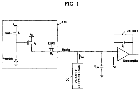
Readout circuit of X-ray detector

The present disclosure relates to a readout circuit of an X-ray detector which includes a data line capacitor to store an electrical signal output from a pixel, an amplifier to amplify the electrical signal from the…

Filed2016
LapsedOct 2025
OwnerVIEWORKS CO., LTD.
Drawing from US 9,778,467 B1Lapsed, fee not paid17 drawings
Hardware & Electronics · US 9,778,467 B1

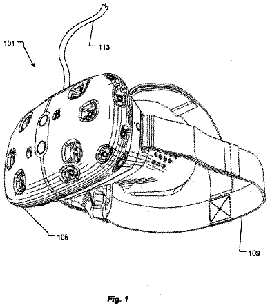
Ride VR headset

A headset for amusement park riders with a removable screen that clips onto headgear.

BuildWorkshop
LapsedOct 2025
OwnerSolo inventor
Drawing from US 9,778,683 B2Lapsed, fee not paid10 drawings
Hardware & Electronics · US 9,778,683 B2

Locking mechanisms to lock key movement of keyboards

An example device in accordance with an aspect of the present disclosure includes a base housing, display housing, and locking mechanism.

Filed2013
LapsedOct 2025
OwnerHewlett-Packard Development Company, L.P.