Cross-reference to related applications
This application is based on and claims priority under 35 USC 119 from Japanese Patent Application No. 2016-034677 filed Feb. 25, 2016. BACKGROUND Technical Field
The present invention relates to image forming apparatuses.
Summary
An image forming apparatus according to an aspect transfers a first image including a first toner not containing a metal pigment onto a specific medium having a smoothness of 112 seconds or smaller, fixes the first image for use as a base coat onto the specific medium, and transfers and fixes a second image including a second toner containing a metal pigment onto the base coat fixed onto the specific medium.
Brief description of the drawings
Exemplary embodiments of the present invention will be described in detail based on the following figures, wherein:
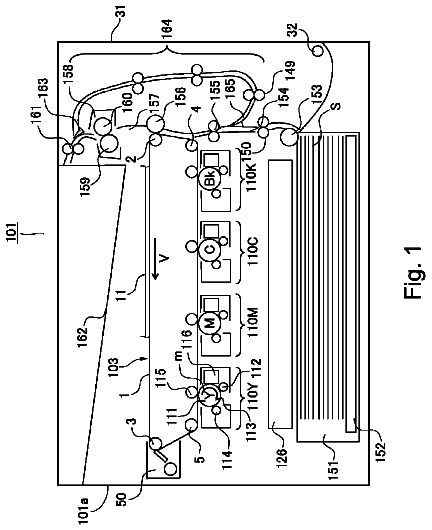
FIG. 1 is a schematic diagram of an image forming apparatus according to a first exemplary embodiment, viewed from the front;
FIG. 2 is a schematic diagram (sectional view) of a silver toner particle used in the image forming apparatus according to the first exemplary embodiment;
FIGS. 3A and 3B are diagrams of particles of toners other than a silver toner used in the image forming apparatus according to the first exemplary embodiment, where FIG. 3A is a schematic diagram (sectional view) of a particle of a Y toner, a M toner, a C toner, and a K toner and FIG. 3B is a schematic diagram (sectional view) of a particle of a CL toner;
FIG. 4 is a flowchart of a mode selection algorithm that a controller uses at a start of an image forming operation according to the first exemplary embodiment;
FIGS. 5A to 5E illustrate an operation of forming an image including a silver toner on a specific medium according to the first exemplary embodiment, where FIG. 5A is a sectional view of a specific medium (before an CL toner image is transferred), FIG. 5B is a sectional view of the specific medium to which a CL toner image has been transferred, FIG. 5C is a sectional view of the specific medium to which the CL toner image has been transferred and fixed, FIG. 5D is a sectional view of the specific medium to which the CL toner image has been fixed and to which a silver toner has been transferred, and FIG. 5E is a sectional view of the specific medium to which the silver toner image has been transferred and to which the silver toner has been fixed;
FIGS. 6A and 6B illustrate a specific medium on which an image including a silver toner is formed according to the first exemplary embodiment, where FIG. 6A is a plan view of the specific medium viewed from the image-formation-surface side (front surface) and FIG. 6B is a sectional view of the specific medium taken along the line VIB-VIB in FIG. 6A ;
FIGS. 7A to 7C illustrate an operation of forming an image including a silver toner on a specific medium according to a first comparative example, where FIG. 7A is a sectional view of a specific medium (before a silver toner image is transferred thereto), FIG. 7B is a sectional view of the specific medium to which a silver toner image has been transferred, and FIG. 7C is a sectional view of the specific medium to which the silver toner image has been fixed;
FIGS. 8A to 8D illustrate an operation of forming an image including a silver toner on a specific medium according to a second comparative example, where FIG. 8A is a sectional view of a specific medium (before a CL toner image is transferred), FIG. 8B is a sectional view of the specific medium to which a CL toner image has been transferred, FIG. 8C is a sectional view of the specific medium to which the CL toner image has been transferred and a silver toner has been transferred, and FIG. 8D is a sectional view of the specific medium to which the CL toner and the silver toner images have been transferred and the CL toner and the silver toner have been fixed;
FIGS. 9A to 9E illustrate an operation of forming an image including a silver toner on a specific medium according to a third comparative example, where FIG. 9A is a sectional view of a specific medium (before a silver toner image is transferred thereto), FIG. 9B is a sectional view of the specific medium to which a silver toner image has been transferred, FIG. 9C is a sectional view of the specific medium to which the silver toner image has been transferred and fixed, FIG. 9D is a sectional view of the specific medium to which the silver toner image has been fixed and a CL toner has been transferred, and FIG. 9E is a sectional view of the specific medium to which the CL toner image has been transferred and the CL toner has been fixed;
FIGS. 10A to 10D illustrate an operation of forming an image including a silver toner on a specific medium according to a fourth comparative example, where FIG. 10A is a sectional view of a specific medium (before a silver toner image is transferred thereto), FIG. 10B is a sectional view of the specific medium to which a silver toner image has been transferred, FIG. 10C is a sectional view of the specific medium to which the silver toner image has been transferred and a CL toner has been transferred, and FIG. 10D is a sectional view of the specific medium to which the silver toner and the CL toner images have been transferred and the silver toner and the CL toner have been fixed;
FIG. 11 is a graph illustrating a luster of an image including a silver toner formed on a specific medium using the image forming apparatus according to the first exemplary embodiment and a luster of an image including a silver toner formed on a specific medium using an image forming apparatus according to each of the first to fourth comparative examples;
FIG. 12 is a graph illustrating a luster of an image including a silver toner formed on a different type of a specific medium using the image forming apparatus according to the first exemplary embodiment and a luster of an image including a silver toner formed on a different type of a specific medium using an image forming apparatus according to each of the first to fourth comparative examples;
FIG. 13 is a schematic view (sectional view) of a silver toner according to a modification example used in each of the image forming apparatuses according to the first to fifth exemplary embodiments;
FIGS. 14A and 14B illustrate an image formation pattern according to a modification example in the case of forming an image including a silver toner on a specific medium using each of the image forming apparatuses according to the first to fifth exemplary embodiments, where FIG. 14A is a plan view of a specific medium viewed from the image-formation-surface side (front surface) and FIG. 14B is a sectional view taken along the line XIVB-XIVB; and
FIG. 15 is a schematic view of an image forming apparatus according to a modification example obtained by modifying the image forming apparatus according to any of the first to fifth exemplary embodiments, when the image forming apparatus according to the modification example is viewed from the front.
Detailed description
Now, exemplary embodiments of the invention (first to fifth exemplary embodiments) are described below. Throughout the description of the exemplary embodiments, directions denoted with arrow X and arrow −X in the drawings represent an apparatus width direction. Directions denoted with arrow Y and arrow −Y in the drawings represent an apparatus height direction. Directions (directions denoted with arrow Z and arrow −Z) perpendicular to the apparatus width direction and the apparatus height direction represent an apparatus depth direction. First Exemplary Embodiment
Referring now to the drawings, a first exemplary embodiment is described below. First, a configuration of an image forming apparatus 10 (see FIG. 1 ) according to this exemplary embodiment is described. Subsequently, an image forming operation of the image forming apparatus 10 according to this exemplary embodiment is described. Thereafter, operation effects of this exemplary embodiment are described.
Configuration of Image Forming Apparatus
Referring now to the drawings, a configuration of the image forming apparatus 10 is described below. Unless otherwise noted, the following description is accompanied with reference to FIG. 1 . The image forming apparatus 10 is an electrophotographic apparatus including a toner-image forming portion 20 , a transfer device 30 , a transporting device 40 , a fixing device 50 , and a controller 60 .
Toner-Image Forming Portion
The toner-image forming portion 20 has a function of forming toner images on each of monochrome units 21 of the toner-image forming portion 20 , described below, by performing a charging process, a light exposure process, and a developing process. After the toner-image forming portion 20 is described, a toner T.sub.G (see FIG. 2 ), toners T.sub.Y, T.sub.M, T.sub.C, and T.sub.K (see FIG. 3A ), and a toner T.sub.CL (see FIG. 3B ) used by the toner-image forming portion 20 are also described herein.
The toner-image forming portion 20 includes, for example, monochrome units 21 G, 21 Y, 21 M, 21 C, 21 K, and 21 CL, which form toner images of different colors (silver (G), yellow (Y), magenta (M), cyan (C), black (K), clear (CL)) on respective photoconductors 22 , described below. The monochrome units 21 G, 21 Y, 21 M, 21 C, 21 K, and 21 CL are arranged in this order from the X side to −X side in the apparatus width direction. The monochrome units 21 G, 21 Y, 21 M, 21 C, 21 K, and 21 CL have the same configuration except that they use different toners, that is, a toner T.sub.G (see FIG. 2 ), toners T.sub.Y, T.sub.M, T.sub.C, and T.sub.K (see FIG. 3A ), and a toner T.sub.CL (see FIG. 3B ). In the following description and the drawings, unless the monochrome units 21 G, 21 Y, 21 M, 21 C, 21 K, and 21 CL and their components need to be distinguished from one another, letters (G, Y, M, C, K, and CL) suffixed to the reference symbols of the monochrome units 21 G, 21 Y, 21 M, 21 C, 21 K, and 21 CL and the toners T.sub.G, T.sub.Y, T.sub.M, T.sub.C, T.sub.K, and T.sub.CL are omitted in the description.
Each monochrome unit 21 includes a cylindrical photoconductor 22 , a charging device 24 , an exposure device 26 , and a development device 28 . The charging device 24 charges the photoconductor 22 with electricity. The exposure device 26 exposes the photoconductor 22 to light (to form a latent image on the photoconductor 22 ). The development device 28 develops a toner image. In the drawings, the reference symbols of components of the monochrome units 21 other than the monochrome unit 21 CL are omitted.
Description of Toners
Now, toners T.sub.G, T.sub.Y, T.sub.M, T.sub.C, T.sub.K, and T.sub.CL are described.
Toner T.sub.G
When toner particles constituting the toner T.sub.G are designated as toner particles MTP, each toner particle MTP contains a metal pigment piece MP and a binder BD 1 , as illustrated in FIG. 2 . Specifically, the toner T.sub.G (or toner particle MTP constituting the toner T.sub.G) contains metal pigment pieces. Here, the toner T.sub.G is an example of a second toner. The binder BD 1 covers each metal pigment piece MP. Each metal pigment piece MP according to this exemplary embodiment has, for example, a flat shape. Specifically, the metal pigment piece MP has, for example, a long-axis length L within a range of, for example, from 5 μm to 12 μm, and a thickness D within a range of, for example, from 0.01 μm to 0.5 μm. Here, the long-axis length L represents a length of a longest portion of the metal pigment piece MP when the metal pigment piece MP is viewed from a direction perpendicular to the thickness direction of the metal pigment piece MP. The toner particle MTP according to this exemplary embodiment has a flat shape as an example.
Toners T.sub.Y, T.sub.M, T.sub.C, and T.sub.K
When the toner particles constituting the toners T.sub.Y, T.sub.M, T.sub.C, and T.sub.K are designated as toner particles NTP, each toner particle NTP contains, for example, resin pigment pieces RP and a binder BD 2 , as illustrated in FIG. 3A . Specifically, the toners T.sub.Y, T.sub.M, T.sub.C, and T.sub.K (or the toner particles NTP constituting the toners T.sub.Y, T.sub.M, T.sub.C, and T.sub.K) do not contain a metal pigment. Each resin pigment piece RP according to this exemplary embodiment is non-flat. Specifically, in each toner particle NTP according to this exemplary embodiment, each resin pigment RP has a long-axis length/thickness ratio of, for example, smaller than 10 and the toner particle NTP has a long-axis length/thickness ratio of, for example, smaller than 2.3. The toner particle NTP according to this exemplary embodiment has, for example, a roundness of 0.90 or greater when projected on a plane. Specifically, the toner particle NTP according to this exemplary embodiment has, for example, a non-flat shape. Here, the resin pigment pieces RP contained in the respective toners T.sub.Y, T.sub.M, T.sub.C, and T.sub.K have different colors.
Toner T.sub.CL
When the toner particles constituting the toner T.sub.CL are designated as toner particles CLTP, each toner particle CLTP contains, for example, a binder BD 3 , as illustrated in FIG. 3B . Specifically, the toner T.sub.CL (or the toner particle CLTP constituting the toner T.sub.CL) does not contain a metal pigment. Here, the toner T.sub.CL is an example of a first toner. The toner particle CLTP according to this exemplary embodiment has, for example, a non-flat shape.
Transfer Device
The transfer device 30 has a function of first-transferring toner images of respective colors formed on the photoconductors 22 of the monochrome units 21 onto a belt TB, described below, and second-transferring the toner images onto a medium P transported by the transporting device 40 . The transfer device 30 includes a belt TB, a driving roller 32 , multiple first transfer rollers 34 , and a second transfer unit 36 . The belt TB is an endless belt and is wound around the driving roller 32 to rotate in the direction of arrow A. Each first transfer roller 34 forms a nip at a portion of the belt TB by nipping the portion of the belt TB together with the photoconductor 22 of the corresponding monochrome unit 21 and first-transfers the toner image of the corresponding color formed on the photoconductor 22 onto the belt TB. The second transfer unit 36 forms a nip at a portion of the belt TB by nipping the belt TB and second-transfers the first-transferred toner image to a medium P that has been transported to the nip by the transporting device 40 . In the following description, among toner images of various colors that have been first-transferred by the first transfer rollers 34 , the toner image formed with the toner T.sub.CL is designated as a first image IM 1 (see FIG. 5B ) and the toner image formed with the toner T.sub.G is designated as a second image IM 2 (see FIG. 5D ).
Transporting Device
The transporting device 40 has a function of transporting a medium P. The transporting device 40 includes a container unit 42 , multiple transport rollers 44 , and a switching device 46 .
The container unit 42 includes a first container 42 A and a second container 42 B, which are capable of separately accommodating different types of medium P. In this exemplary embodiment, the first container 42 A accommodates media P 1 and the second container 42 B accommodates media P 2 . The difference between the media P 1 and the media P 2 is described below. In the following description, unless the media P 1 and the media P 2 need not to be particularly distinguished from each other, they are collectively referred to as media P. The information that the containers 42 A and 42 B respectively accommodate the media P 1 and the media P 2 is stored in a storage device (not illustrated) included in the controller 60 as a result of, for example, a user inputting the information through an interface (not illustrated) of the image forming apparatus 10 .
The multiple transport rollers 44 feed media P accommodated in the containers 42 A and 42 B to a transport path (dot-dash line in the drawing) and transport the media P along the transport path. The directions of arrows B 1 , B 2 , B 3 , B 4 , B 5 , and B 6 in the drawings denote the directions in which the transporting device 40 transports the media P. For example, in a special mode, described below, the multiple transport rollers 44 transport the media P fed from the container unit 42 in this order. Specifically, the multiple transport rollers 44 firstly transport a medium P in the direction of arrow B 1 from the container unit 42 to a second transfer unit 36 . The multiple transport rollers 44 then transport the medium P in the direction of arrow B 2 from the second transfer unit 36 to the fixing device 50 . The multiple transport rollers 44 then transport the medium P in the directions of arrows B 3 and B 4 from the fixing device 50 back to the second transfer unit 36 again. Thereafter, the multiple transport rollers 44 transport the medium P in the direction of arrow B 5 from the second transfer unit 36 to the fixing device 50 and then transport the medium P in the direction of arrow B 6 to eject the medium P out of the image forming apparatus 10 . Here, the speed at which the transporting device 40 transports a medium P is determined to be constant except when the medium P is fed from the container unit 42 .
Description on Medium
As described above, the first container 42 A accommodates media P 1 and the second container 42 B accommodates media P 2 . Here, the media P 1 are media having a smoothness of 112 seconds or smaller (for example, a J sheet manufactured by Fuji Xerox Co., Ltd.). The media P 1 here are an example of specific media. The media P 2 are media having a smoothness of greater than 112 seconds. The unevenness (property of being not smooth or roughness) of the surface of a medium P is said to increase with decreasing smoothness of the medium P. Specifically, in this exemplary embodiment, the media P 1 have a higher surface roughness than the surface roughness of the media P 2 . The smoothness of the media P 1 and the media P 2 is calculated in accordance with JIS 8155 (Paper and board-Determination of smoothness-Oken method).
Fixing Device
The fixing device 50 heats and presses a medium P that has been subjected to a second transfer by the transfer device 30 and transported thereto by the transporting device 40 to fix the toner images to the medium P. The fixing device 50 includes a heating portion 50 A and a pressing portion 50 B. Each of the heating portion 50 A and the pressing portion 50 B according to this exemplary embodiment includes, for example, a roller. The heating portion 50 A and the pressing portion 50 B form a nip as a result of coming into contact with each other so that the toner image is fixed to the medium P that passes through the nip.
Controller
The controller 60 has a function of controlling components other than the controller 60 constituting the image forming apparatus 10 (hereinafter these components are referred to as the components excluding the controller 60 ). The function of the controller 60 is described in the description of the image forming operation.
The above is the description of the configuration of the image forming apparatus 10 according to this exemplary embodiment.
Image Forming Operation
Referring now to FIGS. 4, 5A to 5E, and 6A and 6B , the image forming operation is described below. The image forming operation according to this exemplary embodiment starts with a determination of whether the components excluding the controller 60 are to be operated in a normal mode or a special mode, described below, on the basis of image data that the controller 60 has received from an external device (not illustrated) (see FIG. 4 ). The controller 60 then operates the components excluding the controller 60 to perform the image forming operation in the determined mode. In the following description, an algorithm used for determining the above-described mode is described first. Then, the image forming operation performed by the components excluding the controller 60 is described. Image data include data of types of medium P used for the image forming operation and toner images that are to be fixed to each medium P.
Algorithm Used for Determining Mode
As illustrated in FIG. 4 , when the controller 60 receives image data and starts the image forming operation, the controller 60 determines in a determination step 100 (S 100 in the drawing) whether the medium P that is to be used is the medium P 1 . When the controller 60 makes a positive determination in the determination step 100 , the controller 60 proceeds to a determination of a determination step 110 (S 110 in the drawing). On the other hand, when the controller 60 makes a negative determination in the determination step 100 , the controller 60 operates the components excluding the controller 60 in accordance with a step 120 (S 120 in the drawing) and causes the components excluding the controller 60 to perform an image forming operation in a normal mode, described below.
When the controller 60 makes a positive determination in the determination step 100 and proceeds to the determination step 110 , the controller 60 determines whether the toner T that is to be used includes a toner T.sub.G, that is, whether the toner T.sub.G is to be used. When the controller 60 makes a positive determination in the determination step 110 , the controller 60 operates the components excluding the controller 60 in accordance with a step 130 (S 130 in the drawing) and causes the components excluding the controller 60 to perform an image forming operation in a special mode, described below. On the other hand, when the controller 60 makes a negative determination in the determination step 110 , the controller 60 operates the components excluding the controller 60 in accordance with the step 120 so that the components excluding the controller 60 perform an image forming operation in the normal mode. When the controller 60 finishes determining the mode in which the components excluding the controller 60 performs the image forming operation, the mode determination is complete.
The above is the description of the algorithm used for determining the mode.
Image Forming Operation Performed by Components Excluding Controller 60
Subsequently, an image forming operation performed by the components excluding the controller 60 is described. The normal mode is described first and then the special mode is described. Unless otherwise noted, the image forming operation is described with reference to FIG. 1 .
Normal Mode
The controller 60 that has determined so that the components excluding the controller 60 perform an image forming operation in the normal mode operates the components excluding the controller 60 so that the components excluding the controller 60 perform the image forming operation. The operation is specifically described below.
First, the controller 60 causes the monochrome units 21 to form toner images of different colors (a toner image of a single color in the case of a monochrome image) on the corresponding photoconductors 22 on the basis of the image data. Subsequently, the controller 60 causes the transfer device 30 to first-transfer the toner images of different colors on the photoconductors 22 to the belt TB. The toner images of different colors that have been first-transferred to the belt TB are rotated toward the second transfer unit 36 together with the belt TB. The controller 60 then causes the transporting device 40 to transport a medium P accommodated in the container unit 42 in the direction of arrow B 1 to the second transfer unit 36 . Here, the controller 60 causes the transporting device 40 to transport the medium P such that the toner images of different colors on the belt TB arrive at the second transfer unit 36 at the same time as the medium P arrives at the second transfer unit 36 . Subsequently, the controller 60 causes the second transfer unit 36 to second-transfer the toner images of different colors on the belt TB onto the medium P. The controller 60 then causes the transporting device 40 to transport the medium P on which the toner images have been second-transferred in the direction of arrow B 2 to the fixing device 50 . Thereafter, the controller 60 causes the fixing device 50 to fix the toner images that have been second-transferred to the medium P onto the medium P (to form images on the medium P). The controller 60 then causes the transporting device 40 to transport the medium P on which the images have been formed in the direction of arrow B 6 . Then, the medium P 2 on which the images have been formed is transported by the transporting device 40 in the direction of arrow B 6 and ejected out of the image forming apparatus 10 . Thus, the image forming operation in the normal mode is complete.
The above is the description of the image forming operation in the normal mode.
Special Mode
The controller 60 that has determined so that the components excluding the controller 60 perform an image forming operation in the special mode operates the components excluding the controller 60 so that the components excluding the controller 60 perform the image forming operation. The following describes the case, for example, where an image (see FIGS. 6A and 6B ) of silver “ABC” is formed on a medium P 1 .
First, the controller 60 causes the monochrome unit 21 CL to form a toner image of a clear color (colorless toner image), that is, a first image IM 1 on the photoconductor 22 on the basis of the image data. The first image IM 1 has the same size and the same shape as a silver toner image that is to be formed later on the photoconductor 22 by the monochrome unit 21 G, that is, a second image IM 2 . Subsequently, the controller 60 causes the transfer device 30 to first-transfer the first image IM 1 on the photoconductor 22 of the monochrome unit 21 CL to the belt TB. The first image IM 1 that has been first-transferred to the belt TB is rotated toward the second transfer unit 36 together with the belt TB. The controller 60 causes the transporting device 40 to transport a medium P 1 accommodated in the first container 42 A in the direction of arrow B 1 to the second transfer unit 36 . Thereafter, the controller 60 causes the second transfer unit 36 to second-transfer the first image IM 1 on the belt TB to the medium P 1 (see FIG. 5B ). The controller 60 then causes the transporting device 40 to transport the medium P 1 to which the first image IM 1 has been second-transferred in the direction of arrow B 2 toward the fixing device 50 . The controller 60 then causes the fixing device 50 to fix the first image IM 1 that has been second-transferred to the medium P 1 onto the medium P 1 (see FIG. 5C ). In this case, the controller 60 fixes the first image IM 1 for use as a base coat BS of the second image IM 2 , which is to be formed later. The medium P 1 to which the first image IM 1 has been fixed (medium P 1 on which the base coat BS has been formed) has a smoothness higher than the smoothness of a bare medium P 1 (fixing the first image IM 1 to the medium P 1 enhances the smoothness of the surface of the medium P 1 ).
Subsequently, the controller 60 causes the multiple transport rollers 44 and the switching device 46 to transport the medium P 1 to which the first image IM 1 has been fixed in the direction of arrow B 3 . The controller 60 also causes the monochrome unit 21 G to form a second image IM 2 on the photoconductor 22 on the basis of the image data. Then, the controller 60 causes the transfer device 30 to first-transfer the second image IM 2 on the photoconductor 22 of the monochrome unit 21 G to the belt TB. The controller 60 then causes the second image IM 2 together with the belt TB to rotate toward the second transfer unit 36 . The controller 60 then causes the transporting device 40 to transport the medium P 1 to which the first image IM 1 has been fixed in the direction of arrow B 4 to the second transfer unit 36 . The controller 60 then causes the second transfer unit 36 to second-transfer the first image IM 1 on the belt TB to the medium P 1 (see FIG. 5B ). Thereafter, the controller 60 causes the transporting device 40 to transport the first image IM 1 that has been second-transferred to the medium P 1 toward the fixing device 50 in the direction of arrow B 2 . The controller 60 then causes the fixing device 50 to fix the first image IM 1 to the medium P 1 .
The controller 60 then causes the transporting device 40 to transport the medium P 1 to which the first image IM 1 has been fixed in the direction of arrow B 4 such that the first image IM 1 on the belt TB arrives at the second transfer unit 36 at the same time as the medium P 1 to which the first image IM 1 has been fixed arrives at the second transfer unit 36 . Subsequently, the controller 60 causes the second transfer unit 36 to second-transfer the second image IM 2 onto the medium P 1 to which the first image IM 1 has been fixed such that the second image IM 2 on the belt TB is superposed on the first image IM 1 fixed to the medium P 1 (see FIG. 5D ). The controller 60 then causes the transporting device 40 to transport the medium P to which the second image IM 2 has been second-transferred so as to be superposed on the fixed first image IM 1 in the direction of arrow B 5 to the fixing device 50 . The controller 60 then causes the fixing device 50 to fix the second image IM 2 that has been second-transferred to the medium P 1 onto the medium P 1 at a fixing temperature equivalent to the fixing temperature at which the first image IM 1 is fixed to the medium P 1 (form an image IMG on the medium P 1 ) (see FIG. 5E ). Then, the controller 60 causes the transporting device 40 to transport the medium P 1 on which the image IMG has been formed (see FIGS. 6A and 6B ) in the direction of arrow B 6 . The medium P 1 on which the image IMG has been formed is transported by the transporting device 40 in the direction of arrow B 6 and ejected out of the image forming apparatus 10 . Thus, the image forming operation in the special mode is complete.
As described above, in the case of the image forming apparatus 10 operated in the special mode, the controller 60 operates the components excluding the controller 60 so as to transfer and fix the second image IM 2 on the belt TB onto the colorless base coat BS fixed onto the medium P 1 (see FIG. 5E and FIG. 6B ).
The above is the description of the image forming operation in the special mode.
Operation Effects
Now, operation effects of this exemplary embodiment are described.
First Operation Effect
A first operation effect is an operation effect obtained, when an image IMG including the second image IM 2 is formed on the medium P 1 , by fixing the first image IM 1 onto the medium P 1 for use as the base coat BS and transferring and fixing the second image IM 2 onto the base coat BS. The first operation effect is described on the basis of evaluation results obtained by conducting an evaluation test, described below, in which this exemplary embodiment and comparative examples (first to fourth comparative examples), described below, are compared with one another. When components and the like the same as those used in this exemplary embodiment are used in each of the comparative examples, those components and the like are denoted with the same reference symbols although they may be unillustrated.
Description of configurations of comparative examples
Referring now to the drawings, comparative examples are described below. First Comparative Example
In a first comparative example, the image forming operation is performed in a normal mode, so called in this exemplary embodiment, when a medium P that is to be used is a medium P 1 and a toner T that is to be used includes a toner T.sub.G (see FIGS. 7A, 7B, and 7C ). The first comparative example is similar to this exemplary embodiment except for the above point. Second Comparative Example
In a second comparative example, the image forming operation is performed in a first modification mode modeled after a special mode, so called in this exemplary embodiment, when a medium P that is to be used is a medium P 1 and a toner T that is to be used includes a toner T.sub.G (see FIGS. 8A, 8B, 8C, and 8D ). Here, the first modification mode is a mode in which the first image IM 1 is transferred onto the medium P 1 without being fixed thereto, the second image IM 2 is transferred onto the first image IM 1 , and then the first image IM 1 and the second image IM 2 are fixed onto the medium P 1 (see FIG. 8C ). Specifically, in the second comparative example, the second image IM 2 is transferred onto the first image IM 1 before the first image IM 1 is fixed for use as the base coat BS. The second comparative example is similar to this exemplary embodiment except for the above point. Third Comparative Example
In a third comparative example, the image forming operation is performed in a second modification mode modeled after the special mode, so called in this exemplary embodiment, when a medium P that is to be used is a medium P 1 and a toner T that is to be used includes a toner T.sub.G (see FIGS. 9A, 9B, 9C, 9D, and 9E ). Here, the second modification mode is a mode in which a second image IM 2 is firstly transferred and fixed to the medium P 1 (see FIGS. 9B and 9C ), and then the first image IM 1 is transferred and fixed onto the second image IM 2 fixed onto the medium P 1 (see FIGS. 9D and 9E ). The third comparative example is similar to this exemplary embodiment except for the above point. Fourth Comparative Example
In a fourth comparative example, the image forming operation is performed in a third modification mode modeled after the special mode, so called in this exemplary embodiment, when a medium P that is to be used is a medium P 1 and a toner T that is to be used includes a toner T.sub.G (see FIGS. 10A, 10B, 10C, and 10D ). Here, the third modification mode is a mode in which the second image IM 2 is firstly transferred onto the medium P 1 without being fixed thereto (see FIG. 10A ), and then the first image IM 1 is transferred and fixed onto the second image IM 2 that has been transferred onto the medium P 1 (see FIGS. 10C and 10D ). The fourth comparative example is similar to this exemplary embodiment except for the above point.
Description of Evaluation Test
The evaluation test is described now. In the evaluation test, each of the image forming apparatus 10 according to this exemplary embodiment and image forming apparatuses of the comparative examples (first to fourth comparative examples) forms a sample of a silver ABC image (see FIGS. 6A and 6B ) on a medium P 1 . Then, the metallic luster (Flop Index or F. I.) was measured at the image portion of each sample. Here, the metallic luster was measured in accordance with ASTM E2194.
Results of Evaluation Test and Consideration
The graph of FIG. 11 shows the measurement results of the luster of the samples formed by the image forming apparatus 10 according to this exemplary embodiment and the image forming apparatuses of the comparative examples (first to fourth comparative examples). According to the graph of FIG. 11 , the metallic luster of the sample formed by this exemplary embodiment is higher than the metallic luster of the samples formed by the comparative examples.
In consideration of the results of the evaluation test, the following phenomenon has conceivably occurred in this exemplary embodiment and each comparative example.
Specifically, in the cases of the first, third, and fourth comparative examples, the second image IM 2 is directly fixed to the medium P 1 . Thus, the toner T.sub.G is likely to be so oriented as to follow the shape of the surface of the bare medium P 1 when being fixed to the medium P 1 (when pressed and heated by the fixing device 50 ). Thus, the image IMG has been conceivably formed in the state where the axes of the metal pigment pieces MP are oriented in various directions as illustrated in FIG. 7C , FIG. 9E , and FIG. 10D .
In the case of the second comparative example, the second image IM 2 is transferred onto the first image IM 1 that has not been fixed to the medium P 1 . Thus, while being fixed, the toner T.sub.G is likely to move easily together with the toner T.sub.CL. Thus, the image IMG has been conceivably formed in the state where the axes of the metal pigment pieces MP are oriented in various directions as illustrated in FIG. 8D .
On the other hand, in this exemplary embodiment, unlike the cases of the comparative examples, the first image IM 1 is fixed to the medium P 1 for use as the base coat BS (see FIG. 5C ) and the second image IM 2 is transferred and fixed onto the base coat BS (see FIGS. 5D and 5E ) to form an image IMG including the second image IM 2 on the medium P 1 . The surface of the medium P 1 on which the base coat BS is formed thus becomes smoother than the surface of the bare medium P 1 . Thus, in this exemplary embodiment, flat metal pigment pieces MP contained in the second image are fixed while being oriented so as to follow the shape of the surface smoother than the bare medium P 1 while being fixed. Thus, in this exemplary embodiment, the image IMG has been conceivably formed while the axes of the metal pigment pieces MP are oriented so as to follow the smooth surface, as illustrated in FIG. 5E .
The image forming apparatus 10 according to this exemplary embodiment is thus capable of forming images having a metallic luster higher than that of images formed by directly fixing to the medium P 1 a toner image including a toner containing metal pigment pieces having a flat shape.
The graph in FIG. 12 shows the measurement results of the luster of samples formed on a different example of the medium P 1 , that is, Business 80 gsm (manufactured by Fuji Xerox Co., Ltd.) by the image forming apparatus 10 according to this exemplary embodiment and the image forming apparatus of the first comparative example. Here, Business 80 gsm has a smaller smoothness than the J sheet. The graph of FIG. 12 shows that the metallic luster of the sample according to this exemplary embodiment is higher than the metallic luster of the sample according to the first comparative example.
Second Operation Effect
A second operation effect is an operation effect obtained due to the base coat BS being colorless. The second operation effect is described through a comparison between this exemplary embodiment and a fifth comparative example (not illustrated), described below. When components and the like the same as those used in this exemplary embodiment are used in the fifth comparative example, those components and the like are denoted with the same reference symbols.
In the case of the fifth comparative example, the base coat BS is colored. Thus, in the case of the fifth comparative example, the color of the medium P 1 is not usable as the base color to form the image IMG. Nevertheless, the fifth comparative example has a first operation effect because, when an image IMG including the second image IM 2 is formed on the medium P 1 , the first image IM 1 is fixed to the medium P 1 for use as the base coat BS and the second image IM 2 is then transferred and fixed onto the base coat BS. In other words, the fifth comparative example belongs to the technical scope of the present invention.
The image forming apparatus 10 according to this exemplary embodiment is, on the other hand, capable of using the color of the medium P 1 as a base color to form the image IMG.
The above is the description of the first exemplary embodiment. Second Exemplary Embodiment
The description continues in the full USPTO document.