Lapsed, fee not paid18 drawings
Vehicles & Drones · US 9,777,776 B2
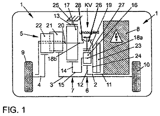
Joint structure and power steering device
A joint structure includes first and second engagement members, and an elastic member.
US 9,778,029 B2 · Assignee: Nissan Motor Co., Ltd. · Inventors: Yamaguchi; Ichiro et al.
Sheet 1 of 29 from the published document. All sheets in the USPTO PDF
A self-position calculating apparatus includes: a light projector configured to project a patterned light beam onto a road surface around a vehicle; an image capturing unit configured to capture and obtain an image of the road surface around the vehicle covering an area of the projected patterned light beam; an orientation angle calculator configured to calculate an orientation angle of the vehicle relative to the road surface from; a feature point detector configured to detect multiple feature points on the road surface; an orientation change amount calculator configured to calculate an amount of change in the orientation of the vehicle; and a self-position calculator configured to calculate a current position and a current orientation angle of the vehicle. The light projector selectively projects the patterned light beam onto a specific patterned light beam-projected region out of the multiple patterned light beam-projected regions.
A technique has been known in which: cameras installed in a vehicle capture and obtain images of surroundings of the vehicle; and an amount of movement of the vehicle is obtained based on changes in the images (see Japanese Patent Application Publication No. 2008-175717). Japanese Patent Application Publication No. 2008-175717 aims at obtaining the amount of movement of the vehicle accurately even if the vehicle moves slightly at slow-speed. To this end, a feature point is detected from each image, the position of the feature point is obtained, and then, the amount of movement of the vehicle is obtained from the direction and distance of movement (amount of movement) of the feature point. In addition, a technique of performing a three-dimensional measurement using a laser light projector for projecting laser light in a grid pattern (patterned light beam) has been known (see Japanese Pate
1 of 29 drawing sheets so far from the published document, cropped to the drawing. Every sheet is in the USPTO PDF.
What the patent claimed, word for word. All of it is now free to use.
The present invention relates to a self-position calculating apparatus and a self-position calculating method.
A technique has been known in which: cameras installed in a vehicle capture and obtain images of surroundings of the vehicle; and an amount of movement of the vehicle is obtained based on changes in the images (see Japanese Patent Application Publication No. 2008-175717). Japanese Patent Application Publication No. 2008-175717 aims at obtaining the amount of movement of the vehicle accurately even if the vehicle moves slightly at slow-speed. To this end, a feature point is detected from each image, the position of the feature point is obtained, and then, the amount of movement of the vehicle is obtained from the direction and distance of movement (amount of movement) of the feature point.
In addition, a technique of performing a three-dimensional measurement using a laser light projector for projecting laser light in a grid pattern (patterned light beam) has been known (see Japanese Patent Application Publication No. 2007-278951). According to Japanese Patent Application Publication No. 2007-278951, an image of an area of the projected patterned light beam is captured with a camera; the patterned light beam is extracted from the captured image; and a behavior of the vehicle is obtained from the positions of the patterned light beam.
In a case where, however, using the technique described in Japanese Patent Application Publication No. 2008-175717 to detect the feature point on the road surface in the same area as the area of the projected patterned light beam described in Japanese Patent Application Publication No. 2007-278951, it is difficult to distinguish between the patterned light beam and the feature point. On the other hand, in a case of detecting the feature point on the road surface in an area away from the area of the projected patterned light beam is projected, an error in calculating an amount of movement of the feature point becomes larger.
With the above problems taken into consideration, an object of the present invention is to provide a self-position calculating apparatus and a self-position calculating method which are capable of easily identifying feature points while distinguishing between the feature points and the patterned light beam, and thereby capable of accurately calculating the self-position of the vehicle.
A self-position calculating apparatus of a first aspect of the present invention projects a patterned light beam onto a road surface around a vehicle; captures and thus obtains an image of the road surface around the vehicle covering an area of the projected patterned light beam is projected; calculates an orientation angle of the vehicle relative to the road surface from a position of the patterned light beam on the obtained image; detects multiple feature points on the road surface from the obtained image; calculates an amount of change in the orientation of the vehicle based on temporal changes in the multiple detected feature points on the road surface; and calculates a current position and a current orientation angle of the vehicle by adding the amount of change in the orientation to an initial position and an initial orientation angle of the vehicle relative to the road surface. The projection of the patterned light beam is achieved by selectively projecting the patterned light beam onto a specific patterned light beam-projected region out of multiple patterned light beam-projected regions depending on how the feature points on the road surface are detected by a feature point detector.
FIG. 1 is a block diagram showing an overall configuration of a self-position calculating apparatus of a first embodiment;
FIG. 2 is an external view showing an example of how a light projector and a camera are installed in a vehicle;
FIG. 3( a ) is a diagram showing how a position of spotlighted areas on a road surface is calculated using the light projector and the camera;
FIG. 3( b ) is a diagram showing how a direction of movement of the camera is obtained from temporal changes in a feature point which is detected outside an area of a patterned light beam projected;
FIG. 4 is a diagram showing an image of a patterned light beam which is obtained by applying a binarization process to an image obtained with the camera with FIG. 4( a ) being a diagram showing the entirety of the patterned light beam, FIG. 4( b ) being a magnified diagram showing one spotlight, and FIG. 4( c ) being a diagram showing a position of the center of gravity of spotlights;
FIG. 5 is a schematic diagram for describing a method of calculating amounts of changes in a distance and orientation angle;
FIG. 6 is a diagram showing feature points detected on the image with FIG. 6( a ) being a diagram showing a first frame (image) obtained at time t and FIG. 6( b ) being a diagram showing a second frame obtained at time t+Δt;
FIG. 7( a ) is a diagram showing an image obtained by the camera;
FIG. 7( b ) is a diagram showing an image of the patterned light beam which is obtained by applying a binarization process to the image obtained by the camera;
FIG. 7( c ) is a diagram showing a result of detecting feature points;
FIG. 8 is a schematic diagram showing an example of patterned light beam-projected regions divided in vertical and left-right directions;
FIG. 9( a ) is a schematic diagram showing an example of detected feature points;
FIG. 9( b ) is a schematic diagram showing an example of a selected patterned light beam-projected region;
FIG. 10( a ) is a graph showing how the selected patterned light beam-projected region changes from one to another over time;
FIG. 10( b ) is a graph showing a temporal change in the number of feature points detected from each patterned light beam-projected region;
FIG. 11 is a flowchart for explaining an example of a self-position calculating method of the first embodiment;
FIG. 12 is a flowchart showing details of step S 01 ;
FIG. 13( a ) is a schematic diagram showing an example of detected feature points;
FIG. 13( b ) is a schematic diagram showing an example of selected patterned light beam-projected regions;
FIG. 14( a ) is a graph showing how a light projection flag for each patterned light beam-projected region changes over time;
FIG. 14( b ) is a graph showing a temporal change in the number of feature points detected from each patterned light beam-projected region;
FIG. 15 is a schematic diagram showing an example of patterned light beam-projected regions alternately arranged one after another like longitudinal stripes;
FIG. 16( a ) is a schematic diagram showing an example of detected feature points;
FIG. 16( b ) is a schematic diagram showing an example of a selected set of patterned light beam-projected regions;
FIG. 17( a ) is a graph showing how the selected set of patterned light beam-projected regions changes from one to another over time;
FIG. 17( b ) is a graph showing a temporal change in the number of feature points detected from each set of patterned light beam-projected regions;
FIG. 18 is a schematic diagram showing an example of two patterned light beam-projected regions divided in a left-right direction;
FIG. 19( a ) is a schematic diagram showing an example of detected feature points;
FIG. 19( b ) is a schematic diagram showing an example of a selected patterned light beam-projected region;
FIG. 20 is a schematic diagram showing an example of spotlights-projected regions;
FIG. 21( a ) is a schematic diagram showing an example of detected feature points;
FIG. 21( b ) is a schematic diagram showing an example of selected patterned light beam-projected regions;
FIG. 22( a ) is a graph showing how a light projection flag for each spotlight changes over time;
FIG. 22( b ) is a graph showing how a result of determining whether or not a feature point exists at a position of each spotlight changes over time;
FIG. 23 is a block diagram showing an overall configuration of a self-position calculating apparatus of a second embodiment;
FIG. 24( a ) is a schematic diagram showing an example of detected feature points;
FIG. 24( b ) is a schematic diagram showing an example of selected patterned light beam-projected regions;
FIG. 25( a ) is a graph showing how a light projection flag for each spotlight changes over time;
FIG. 25( b ) is a graph showing how a result of estimating whether or not a feature point exists at a position of each spotlight changes over time;
FIG. 26 is a flowchart showing an example of details of step S 01 of the second embodiment;
FIG. 27 is a schematic diagram showing an example of four patterned light beam-projected regions divided in a vehicle-width direction;
FIG. 28( a ) is a schematic diagram showing a method of setting feature-points increase/decrease prediction areas, and an example of detected feature points;
FIG. 28( b ) is a schematic diagram showing an example of selected patterned light beam-projected regions;
FIG. 29( a ) is a graph showing how a light projection flag for each spotlight changes over time;
FIG. 29( b ) is a graph showing how a result of determining whether or not there exist feature points in each feature-points increase/decrease prediction area changes over time; and
FIG. 30 shows an example of a flowchart to be followed when it is determined whether to calculate the angle and orientation relative to the road surface.
Referring to the drawings, descriptions will be hereinbelow provided for first and second embodiments to which the present invention is applied.
[First Embodiment]
[Hardware Configuration]
To begin with, referring to FIG. 1 , descriptions will be provided for a hardware configuration of a self-position calculating apparatus of a first embodiment. The self-position calculating apparatus includes a light projector 11 , a camera 12 and an engine control unit (ECU) 13 . The light projector 11 is installed in a vehicle, and projects a patterned light beam onto a road surface around the vehicle. The camera 12 is installed in the vehicle, and is an example of an image capturing unit configured to capture and thus obtain images of the road surface around the vehicle, inclusive of an area of the patterned light beam projected. The ECU 13 is an example of a controller configured to control the light projector 11 , and to perform a series of information process cycles for calculating the self-position of the vehicle from images obtained with the camera 12 .
The camera 12 is a digital camera using a solid-state image sensor such as a CCD and a CMOS, and obtains processable digital images. What the camera 12 captures is the road surface around the vehicle. The road surface around the vehicle includes road surfaces in front of, in the back of, at sides of, and beneath the vehicle. As shown in FIG. 2 , the camera 12 may be installed in a front section of the vehicle 10 , more specifically above a front bumper, for example. The height at and direction in which to set the camera 12 are adjusted in a way that enables the camera 12 to capture images of feature points (textures) on the road surface 31 in front of the vehicle 10 and the patterned light beam 32 b projected from the light projector 11 . The focus and diaphragm of the lens of the camera 12 are automatically adjusted as well. The camera 12 repeatedly captures images at predetermined time intervals, and thereby obtains a series of image (frame) groups. Each time the camera 12 captures an image, image data obtained with the camera 12 is transferred to the ECU 13 , and is stored in a memory included in the ECU 13 .
As shown in FIG. 2 , the light projector 11 projects the patterned light beam 32 b having a predetermined shape, inclusive of a square or rectangular lattice shape, onto the road surface 31 within an image capturing range of the camera 12 . The camera 12 captures images of the patterned light beam projected onto the road surface 31 . The light projector 11 includes a laser pointer and a diffraction grating, for example. The diffraction grating diffracts the laser beam projected from the pointer. Thereby, as shown in FIGS. 2 to 4 , the light projector 11 generates the patterned light beam ( 32 b , 32 a ) which includes multiple spotlights arranged in a lattice or matrix pattern. In examples shown in FIGS. 3 and 4 , the light projector 11 generates the patterned light beam 32 a including 5×7 spotlights.
Returning to FIG. 1 , the ECU 13 includes a CPU, a memory, and a microcontroller including an input-output section. By executing pre-installed computer programs, the ECU 13 forms multiple information processors which function as the self-position calculating apparatus. For each image (frame), the ECU 13 repeatedly performs the series of information process cycles for calculating the self-position of the vehicle from images obtained with the camera 12 . Incidentally, the ECU 13 may be also used as an ECU for controlling other systems of the vehicle 10 .
In this respect, the multiple information processors include a patterned light beam extractor 21 , an orientation angle calculator 22 , a feature point detector 23 , an orientation change amount calculator 24 , a self-position calculator 25 , and a patterned light beam controller 26 .
The patterned light beam extractor 21 reads an image obtained with the camera 12 from the memory, and extracts the position of the patterned light beam from this image. For example, as shown in FIG. 3( a ) , the light projector 11 projects the patterned light beam 32 a , which includes the multiple spotlights arranged in a matrix pattern, onto the road surface 31 , while the camera 12 detects the patterned light beam 32 a reflected off the road surface 31 . The patterned light beam extractor 21 applies a binarization process to the image obtained with the camera 12 , and thereby extracts only an image of the spotlights Sp, as shown in FIGS. 4( a ) and 4( b ) . Thereafter, as shown in FIG. 4( c ) , the patterned light beam extractor 21 extracts the position of the patterned light beam 32 a by calculating the center-of-gravity position He of each spotlight Sp, that is to say, the coordinates (Uj, Vj) of each spotlight Sp on the image. The coordinates are expressed using the number assigned to a corresponding pixel in the image sensor of the camera 12 . In a case where the patterned light beam includes 5×7 spotlights Sp, “j” is an integer not less than 1 but not greater than 35. The memory stores the coordinates (Uj, Vj) of the spotlight Sp on the image as data on the position of the patterned light beam 32 a.
The orientation angle calculator 22 reads the data on the position of the patterned light beam 32 a from the memory, and calculates the distance and orientation angle of the vehicle 10 relative to the road surface 31 from the position of the patterned light beam 32 a on the image obtained with the camera 12 . For example, as shown in FIG. 3( a ) , using the trigonometrical measurement principle, the orientation angle calculator 22 calculates the position of each spotlighted area on the road surface 31 , as the position of the spotlighted area relative to the camera 12 , from a base length Lb between the light projector 11 and the camera 12 , as well as the coordinates (Uj, Vj) of each spotlight on the image. Thereafter, the orientation angle calculator 22 calculates a plane equation of the road surface 31 onto which the patterned light beam 32 a is projected, that is to say, the distance and orientation angle (normal vector) of the camera 12 relative to the road surface 31 , from the position of each spotlight relative to the camera 12 .
It should be noted that in the embodiment, the distance and orientation angle of the camera 12 relative to the road surface 31 are calculated as an example of the distance and orientation angle of the vehicle 10 relative to the road surface 31 since the position of installation of the camera 12 in the vehicle 10 and the angle for the camera 12 to capture images are already known. In other words, the distance between the road surface 31 and the vehicle 10 , as well as the orientation angle of the vehicle 10 relative to the road surface 31 can be obtained by calculating the distance and orientation angle of the camera 12 relative to the road surface 31 .
To put it specifically, since the camera 12 and the light projector 11 are fixed to the vehicle 10 , the direction in which to project the patterned light beam 32 a and the distance (the base length Lb) between the camera 12 and the light projector 11 are already known. For this reason, using the trigonometrical measurement principle, the orientation angle calculator 22 is capable of obtaining the position of each spotlighted area on the road surface 31 , as the position (Xj, Yj, Zj) of each spotlight relative to the camera 12 , from the coordinates (Uj, Vj) of each spotlight on the image. Hereinafter, the distance and orientation angle of the camera 12 relative to the road surface 31 will be abbreviated as “distance and orientation angle.” The distance and orientation angle calculated by the orientation angle calculator 22 are stored into the memory.
It should be noted that the descriptions are provided for the embodiment in which the distance and orientation angle are calculated in each information process cycle.
Furthermore, in many cases, the position (Xj, Yj, Zj) of each spotlight relative to the camera 12 is not present on the same plane. This is because the relative position of each spotlight changes according to the unevenness of the asphalt of the road surface 31 . For this reason, the method of least squares may be used to obtain a plane equation which minimizes the sum of squares of distance difference of each spotlight. Data on the thus-calculated distance and orientation angle is used by the self-position calculator 25 shown in FIG. 1 .
The feature point detector 23 reads the image obtained with the camera 12 from the memory, and detects feature points on the road surface 31 from the image read from the memory. In order to detect the feature points on the road surface 31 , the feature point detector 23 may use a method described in “D. G. Lowe, “Distinctive Image Features from Scale-Invariant Keypoints,” Int. J. Comput. Vis., vol. 60, no. 2, pp. 91-110, November 200.” Otherwise, the feature point detector 23 may use a method described in “Kanazawa Yasushi, Kanatani Kenichi, “Detection of Feature Points for Computer Vision,” IEICE Journal, vol. 87, no. 12, pp. 1043-1048, December 2004.”
To put it specifically, for example, the feature point detector 23 uses the Harris operator or the SUSAN operator as that points, such as apexes of an object, the luminance values of which are largely different from those of the vicinities of the points are detected as the feature points. Instead, however, the feature point detector 23 may use a SIFT (Scale-Invariant Feature Transform) feature amount so that points around which the luminance values change with certain regularity are detected as the feature points. After detecting the feature points, the feature point detector 23 counts the total number N of feature points detected from one image, and assigns identification numbers (i (1≦i≦N)) to the respective feature points. The position (Ui, Vi) of each feature point on the image are stored in the memory inside the ECU 13 . FIGS. 6( a ) and 6( b ) each shows examples of the feature points Te which are detected from the image captured with the camera 12 . Furthermore, in FIGS. 6( a ) and 6( b ) , directions of changes of, and amounts of changes in, the feature points Te are expressed with vectors Dte, respectively.
It should be noted that the present embodiment treats particles of asphalt mixture with a particle size of not less than 1 cm but not greater than 2 cm as the feature points on the road surface 31 . The camera 12 employs the VGA resolution mode (approximate 300 thousand pixels) in order to detect the feature points. In addition, the distance from the camera 12 to the road surface 31 is approximately 70 cm. Moreover, the direction in which the camera 12 captures images is tilted at approximately 45 degrees to the road surface 31 from the horizontal plane. What is more, the luminance value of each image captured with the camera 12 and thereafter sent to the ECU 13 is within a range of 0 to 255 (0: darkest, 255: brightest).
The orientation change amount calculator 24 reads, from the memory, the positional coordinates (Ui, Vi) of each of the multiple feature points on an image included in a previous image frame (at time t) which is among the image flames captured at each certain information process cycle. Furthermore, the orientation change amount calculator 24 reads, from the memory, the positional coordinates (Ui, Vi) of each of the multiple feature points on the image included in the current frame (at time t+Δt). Thereafter, based on the temporal changes in the positions of the multiple feature points, the orientation change amount calculator 24 obtains an amount of change in the orientation of the vehicle. In this respect, the amount of change in the orientation of the vehicle includes both “amounts of changes in the distance and orientation angle” of the vehicle relative to the road surface and an “amount of movement of the vehicle” on the road surface. Descriptions will be hereinbelow provided for how to calculate the “amounts of changes in the distance and orientation angle” and the “amount of movement of the vehicle”.
The amounts of changes in the distance and orientation angle can be obtained as follows, for example. FIG. 6( a ) shows an example of a first frame (image) 38 (in FIG. 5 ) captured at time t. Let us assume a case where as shown in FIGS. 5 and 6 ( a ), a relative position (Xi, Yi, Zi) of each of three feature points Te 1 , Te 2 , Te 3 are calculated on the first frame 38 , for example. In this case, a plane G (see FIG. 6( a ) ) identified by the feature points Te 1 , Te 2 , Te 3 can be regarded as the road surface. Accordingly, the orientation change amount calculator 24 is capable of obtaining the distance and orientation angle (normal vector) of the camera 12 relative to the road surface (the plane G), from the relative position (Xi, Yi, Zi) of each of the feature points. Furthermore, from an already-known camera model, the orientation change amount calculator 24 is capable of obtaining a distance 11 between the feature points Te 1 , Te 2 , a distance 12 between the feature points Te 2 , Te 3 and a distance 13 between the feature points Te 3 , Te 1 , as well as an angle between a straight line joining the feature points Te 1 , Te 2 and a straight line joining the feature points Te 2 , Te 3 , an angle between the straight line joining the feature points Te 2 , Te 3 and a straight line joining the feature points Te 3 , Te 1 , and an angle between the straight line joining the feature points Te 3 , Te 1 and the straight line joining the feature points Te 1 , Te 2 . The camera 12 in FIG. 5 shows where the camera is located when camera captures the first frame.
It should be noted that in FIG. 5 , the three-dimensional coordinates (Xi, Yi, Zi) of the relative position of each feature point relative to the camera 12 are set in a way that: the Z-axis coincides with the direction in which the camera 12 captures the image; and the X and Y axes orthogonal to each other in a plane including the camera 12 are lines normal to the direction in which the camera 12 captures the image. Meanwhile, the coordinates on the image 38 are set such that: the V-axis coincides with the horizontal direction; and the U-axis coincides with the vertical direction.
FIG. 6( b ) shows a second frame 38 ′ obtained at time (t+Δt) where the time length Δt passed from time t. A camera 12 ′ in FIG. 5 shows where the camera is located when camera captures the second frame 38 ′. As shown in FIGS. 5 and 6 ( b ), the camera 12 ′ captures an image including the feature points Te 1 , Te 2 , Te 3 as the second frame 38 ′, and the feature point detector 23 detects the feature points Te 1 , Te 2 , Te 3 from the image. In this case, the orientation change amount calculator 24 is capable of calculating an amount ΔL of movement of the camera 12 in the interval of time Δt from: the relative position (Xi, Yi, Zi) of each of the feature points Te 1 , Te 2 , Te 3 at time t; a position P 1 (Ui, Vi) of each feature point on the second frame 38 ′; and the camera model of the camera 12 . Accordingly, the orientation change amount calculator 24 is capable of calculating the amount of movement of the vehicle. Furthermore, the orientation change amount calculator 24 is capable of calculating the amounts of changes in the distance and orientation angle as well. For example, the orientation change amount calculator 24 is capable of calculating the amount (ΔL) of movement of the camera 12 (the vehicle) and the amounts of changes in the distance and orientation angle of the camera 12 (the vehicle) by solving the following system of simultaneous equations
to (4). Incidentally, the equation
mentioned below is based on an ideal pinhole camera free from strain and optical axial misalignment which is modeled after the camera 12 , where λi and f denote a constant and a focal length. The parameters of the camera model may be calibrated in advance.
[ Equation ( 1 ) ] λ i [ u i v i 1 ] = [ f 0 0 0 f 0 0 0 1 ] [ x i y i z i ] ( 1 ) [ Equation ( 2 ) ] ( x 1 - x 2 ) 2 + ( y 1 - y 2 ) 2 + ( z 1 - z 2 ) 2 = l 1 2 ( 2 ) [ Equation ( 3 ) ] ( x 3 - x 2 ) 2 + ( y 3 - y 2 ) 2 + ( z 3 - z 2 ) 2 = l 2 2 ( 3 ) [ Equation ( 4 ) ] ( x 1 - x 3 ) 2 + ( y 1 - y 3 ) 2 + ( z 1 - z 3 ) 2 = l 3 2 ( 4 )
It should be noted that instead of using all the feature points whose relative positions are calculated in the images detected at time t and time t+Δt, the orientation change amount calculator 24 may select optimum feature points based on positional relationships among the feature points. An example of a selection method usable for this purpose is the epipolar geometry (the epipolar line geometry described in R. I. Hartley, “A linear method for reconstruction from lines and points,” Proc. 5th International Conference on Computer Vision, Cambridge, Mass., pp. 882-887 (1995)).
If like in this case, the feature points Te 1 , Te 2 , Te 3 , the relative positions of which on the frame image 38 at time t are calculated, are detected by the feature point detector 23 from the frame image 38 ′ at time t+Δt as well, the orientation change amount calculator 24 is capable of calculating the “amount of change in the orientation angle of the vehicle” from the temporal changes in the relative positions (Xi, Yi, Zi) of the respective feature points on the road surface and the temporal changes of the positions (Ui, Vi) of the respective feature points on the image. Furthermore, the orientation change amount calculator 24 is capable of calculating the amount of movement of the vehicle.
To put it specifically, if three or more feature points each corresponding between the previous and current frames can be detected continuously from the two frames, the continuation of the process (integration operation) of adding the amounts of changes in the distance and orientation angle makes it possible to continuously update the distance and orientation angle without using the patterned light beam 32 a . Nevertheless, the distance and orientation angle calculated using the patterned light beam 32 a , or a predetermined initial position and orientation angle, may be used for the first information process cycle. In other words, the distance and orientation angle which are starting points of the integration operation may be calculated using the patterned light beam 32 a , or may be set at predetermined initial values. It is desirable that the predetermined initial position and the predetermined initial orientation angle are a distance and an orientation angle determined with at least the occupants and payload of the vehicle 10 taken into consideration. For example, the distance and orientation angle calculated using the patterned light beam 32 a which is projected while the ignition switch of the vehicle 10 is on and when the shift position is moved from the parking position to another position may be used as the predetermined initial position and the predetermined initial orientation angle. Thereby, it is possible to obtain the distance and orientation angle which is not affected by the roll or pitch of the vehicle 10 due to a turn, acceleration or deceleration of the vehicle 10 .
It should be noted that the associating of the feature points in the current frame with the feature points in the previous frame may be achieved, for example, by: storing an image of a small area around each detected feature point into the memory; and for each feature point, making a determination from a similarity in luminance information and a similarity in color information. To put it specifically, the ECU 13 stores a 5 (horizontal)×5 (vertical)-pixel image around each detected feature point into the memory. If for example, the difference in the luminance information among 20 or more pixels is equal to or less than 1%, the orientation change amount calculator 24 determines that the feature points in question correspond between the current and previous frames. Thereafter, the amount of change in the orientation obtained through the foregoing process is used by the self-position calculator 25 in the next process step to calculate the self-position of the vehicle 10 .
The self-position calculator 25 calculates the current distance and orientation angle of the vehicle 10 from the “amounts of changes in the distance and orientation angle” calculated by the orientation change amount calculator 24 . In addition, the self-position calculator 25 calculates the self-position of the vehicle 10 from the “amount of movement of the vehicle” calculated by the orientation change amount calculator 24 .
Descriptions will be provided for how to perform the foregoing calculations in a specific case where the distance and orientation angle calculated by the orientation angle calculator 22 (that is to say, the distance and orientation angle calculated using the patterned light beam) are set as the starting points of the calculations. In this case, the self-position calculator 25 updates the distance and orientation angle with the most recent numerical values by sequentially adding (performing an integration operation on) the amounts of changes in the distance and orientation angle calculated for each frame by the orientation change amount calculator 24 to the starting points, that is to say, the distance and orientation angle calculated by the orientation angle calculator 22 . In addition, the self-position calculator 25 calculates the self-position of the vehicle by: setting the position of the vehicle, which is obtained when the orientation angle calculator 22 calculates the distance and orientation angle, as the starting point (the initial position of the vehicle); and by sequentially adding (performing an integration operation on) the amount of movement of the vehicle to the initial position of the vehicle. For example, by setting the starting point (the initial position of the vehicle) which matches the position of the vehicle on a map, the self-position calculator 25 is capable of sequentially calculating the current self-position of the vehicle on the map.
Thereby, the orientation change amount calculator 24 is capable of calculating the self-position of the vehicle by obtaining the amount (ΔL) of movement of the camera 12 for the time length Δt. In addition, the orientation change amount calculator 24 is capable of calculating the amounts of changes in the distance and orientation angle at the same time. For these reasons, with the amounts of changes in the distance and orientation angle of the vehicle taken into consideration, the orientation change amount calculator 24 is capable of accurately calculating the amount (ΔL) of movement in six degrees of freedom (forward/rearward moving, leftward/rightward moving, upward/downward moving, yawing, pitching and rolling). In other words, an error in estimating the amount (ΔL) of movement can be minimized even if the distance and orientation angle are changed by the roll or pitch due to the turn, acceleration or deceleration of the vehicle 10 .
In the present embodiment, the amount (ΔL) of movement of the camera 12 is calculated by: calculating the amounts of changes in the distance and orientation angle; and updating the distance and orientation angle. Instead, however, the amount (ΔL) of movement of the camera 12 may be calculated by: calculating the amount of change in only the orientation angle of the camera 12 relative to the road surface 31 ; and updating only the orientation angle of the camera 12 . In this case, it may be supposed that the distance between the road surface 31 and the camera 12 remains constant. This makes it possible to reduce the operation load on the ECU 13 while minimizing the error in estimating the amount (ΔL) of movement with the amount of change in the orientation angle taken into consideration, and to increase the operation speed of the ECU 13 .
The patterned light beam controller 26 controls the projection of the patterned light beam 32 a by the light projector 11 . For example, after the ignition switch of the vehicle 10 is turned on, once the self-position calculating apparatus becomes activated, the patterned light beam controller 26 starts to project the patterned light beam 32 a . Thereafter, until the self-position calculating apparatus stops its operation, the patterned light beam controller 26 continues projecting the patterned light beam 32 a . Otherwise, the patterned light beam controller 26 may alternately turn on and off the light projection in predetermined intervals.
In the case where the patterned light beam 32 a including 5×7 spotlights SP is projected, an image as shown in FIG. 7( a ) is obtained by the camera 12 . Applying the binarization process to the image, the patterned light beam extractor 21 can extract the patterned light beam (spotlights) Sp as shown in FIG. 7( b ) . Meanwhile, the feature point detector 23 has difficulty in detecting feature points on the road surface 31 from the same area as an area of the projected patterned light beam Sp, because as shown in FIG. 7( c ) , it is difficult to identify the feature points on the road surface 31 against the patterned light beam Sp. In contrast to this, when feature points on the road surface 31 are detected by the feature point detector 23 from an area away from the area of the patterned light beam 32 a projected, errors in calculating amounts of movements of the feature points become larger.
With this taken into consideration, the embodiment is configured such that depending on how the feature points on the road surface are detected by the feature point detector 23 , the patterned light beam controller 26 selectively projects the patterned light beam onto a specific one of multiple patterned light beam-projected regions.
For example, as shown in FIG. 8 , the patterned light beam controller 26 sets the multiple (four) patterned light beam-projected regions A to D within an image capturing area 30 . In FIG. 8 , an arrow 41 denotes a movement direction of the vehicle, while an arrow 42 pointed in a direction opposite to that of the arrow 41 denotes a movement direction of the feature points. The patterned light beam-projected regions A to D are four parts into which the image capturing area 30 is divided in the movement direction 41 of the vehicle (in a vertical direction) and in a vehicle-width direction orthogonal to the movement direction 41 of the vehicle (in a left-right direction), and are arranged in a rectangular pattern. Incidentally, the number of patterned light beam-projected regions is plural, and no other restriction is imposed in the number of regions. Two or three patterned light beam-projected regions may be set therein. Otherwise, five or more patterned light beam-projected regions may be set therein.
Suppose a case where as shown in FIG. 9( a ) , the feature points Te are detected by the feature point detector 23 . For each of the patterned light beam-projected regions A to D, the patterned light beam controller 26 counts the number of feature points Te detected therein. Meanwhile, for each of the patterned light beam-projected regions A to D, the patterned light beam controller 26 may count the number of feature points falling within the region. Otherwise, for each of the patterned light beam-projected regions A to D, the patterned light beam controller 26 may count the number of detected feature points by including: feature points falling within the region; and feature points Te lying on the boundaries of the region with their parts belonging to the region.
In the case shown in FIG. 9( a ) , the counted number of feature points detected as falling within the patterned light beam-projected region A is one; the region B, four; the region C, four; and the region D, three. The patterned light beam controller 26 causes the light beam to be selectively projected onto the patterned light beam-projected region A where the number of feature points is the smallest among the patterned light beam-projected regions A to D, as shown in FIG. 9( b ) .
FIG. 10( a ) shows how a selected patterned light beam-projected region changes from one to another over time. For each of the patterned light beam-projected regions A to D, FIG. 10( b ) shows a temporal change in the number of feature points detected therein. Times t 0 to t 7 represent times at which the corresponding information process cycles are performed. At time t 0 , when the patterned light beam controller 26 counts the number of feature points Te detected by the feature point detector 23 , the number of detected feature points is the smallest in the patterned light beam-projected region A, as shown in FIG. 10( b ) . Thus, as shown in FIG. 10( a ) , at time t 1 of the next information process cycle, the patterned light beam controller 26 causes the light beam to be selectively projected onto the patterned light beam-projected region A where the number of feature points is the smallest at time t 0 of the previous information process cycle.
Similarly, at times t 1 to t 6 , the patterned light beam controller 26 counts the number of feature points. Thus, at time t 2 to t 7 of the corresponding next information process cycles, the patterned light beam controller 26 causes the light beam to be selectively projected onto a patterned light beam-projected region where the number of feature points is the smallest at time t 1 to t 6 of the previous information process cycles.
[Information Process Cycle]
Next, referring to FIG. 11 , descriptions will be provided for the information process cycle to be repeatedly performed by the ECU 13 . The information process cycle is an example of a self-position calculating method of calculating the self-position of the vehicle 10 from the image 38 obtained with the camera 12 .
The information process cycle shown in a flowchart of FIG. 11 is started at the same time as the self-position calculating apparatus becomes activated after the ignition switch of the vehicle 10 is turned on, and is repeatedly performed until the self-position calculating apparatus stops its operation.
In step S 01 in FIG. 11 , the patterned light beam controller 26 controls the light projector 11 to make the light projector 11 to project the patterned light beam 32 a onto the road surface 31 . Using the flowchart in FIG. 11 , descriptions will be provided for a case where the patterned light beam 32 a is continuously projected. Note that details of step S 01 will be described later.
The description continues in the full USPTO document.
About 6,992 words. The USPTO PDF has it with every drawing.
Fees are due 3.5, 7.5 and 11.5 years after grant. This patent expired on October 3, 2025, so the fee marked "not paid" was the one that went unpaid.
Self-Position Calculating Apparatus and Self-Position Calculating Method
Filed Feb 2014 · published Jan 2017Self-position calculating apparatus and self-position calculating method
Filed Feb 2014 · granted Oct 2017Earlier publications, parents and continuations. None of them can still be enforced, or this patent would not be listed.
Prior art cited by the examiner or applicant. Useful when you check your own idea for novelty.
Everything on this page comes from the documents linked above.