Lapsed, fee not paid2 drawings
Vehicles & Drones · US 9,776,658 B2
Apparatus for turning steerable vehicle wheels
An apparatus for use in turning steerable vehicle wheels includes an axially movable steering member.
US 9,776,660 B2 · Assignee: Honda Motor Co., Ltd. · Inventors: Imanishi; Tomoyuki et al.
Sheet 1 of 22 from the published document. All sheets in the USPTO PDF
A vehicle subframe is provided with a main body formed in a hollow shape by a core unit. The subframe includes: a top parallel section and a bottom rear parallel section provided to the top and the bottom of the main body; a top left sand elimination opening and a top right sand eliminating opening formed at the top parallel section; and a left bottom rear sand elimination opening and a right bottom rear sand elimination opening formed at the bottom rear parallel section. The left bottom rear sand elimination opening is provided to a site opposing the top left sand elimination opening, and is formed in a shape equivalent to the top left sand elimination opening. The right bottom rear sand elimination opening is provided to a site opposing the top right sand elimination opening, and is formed in a shape equivalent to the top right sand elimination opening.
Some known vehicles include a subframe made by casting and provided on a vehicle frame for supporting thereon a structural component such as a transmission. The subframe is formed into a hollow shape by means of a core which is disposed in a cavity of a casting mold when the subframe is formed by casting. The subframe further has a core discharge opening (hereinafter referred to as “sand discharge opening”) formed at a bottom part thereof for allowing the core to be discharged after casting. By virtue of the hollow shape, the subframe is made light in weight (See, Patent Document 1, for example). PRIOR ART LITERATURE Patent Documents [Patent Document 1] Japanese Patent Application Laid-open Publication (JP-A) No. 2009-298402 SUMMARY OF INVENTION Technical Problems When the sand discharge opening formed at the bottom part of the subframe is to be produced, the core must be directly suppor
1 of 22 drawing sheets so far from the published document, cropped to the drawing. Every sheet is in the USPTO PDF.
What the patent claimed, word for word. All of it is now free to use.
The present invention relates to a vehicle subframe provided under a vehicle body for supporting left and right suspensions at left and right end portions thereof.
Some known vehicles include a subframe made by casting and provided on a vehicle frame for supporting thereon a structural component such as a transmission. The subframe is formed into a hollow shape by means of a core which is disposed in a cavity of a casting mold when the subframe is formed by casting. The subframe further has a core discharge opening (hereinafter referred to as “sand discharge opening”) formed at a bottom part thereof for allowing the core to be discharged after casting. By virtue of the hollow shape, the subframe is made light in weight (See, Patent Document 1, for example). PRIOR ART LITERATURE Patent Documents
[Patent Document 1] Japanese Patent Application Laid-open Publication (JP-A) No. 2009-298402 SUMMARY OF INVENTION Technical Problems
When the sand discharge opening formed at the bottom part of the subframe is to be produced, the core must be directly supported by either of a fixed mold and a movable mold. In this instance, the core is subjected to a pressure applied from only one of the fixed mold and the movable mold.
Under such condition, it may occur that in casting a subframe, the core is displaced by a molten metal flowing into the cavity. Displacement of the core will make it difficult to produce a subframe having a uniform wall thickness, allowing the generation of a thickened wall-thickness part, which will hinder weight reduction of the subframe. The difficulty in forming a uniform wall thickness for the subframe also causes hindrance to uniform distribution of strength over the entire area of the subframe.
An object of the present invention is to provide a vehicle subframe which is capable of making the wall thickness uniform and which can secure desired rigidity and strength. Solutions to Problems
According to one aspect of the present invention, there is provided a vehicle subframe cast-molded into a unitary structure using a core, the vehicle subframe comprising a body formed into a hollow shape by means of the core and including a top wall and a bottom wall spaced from each other in a vertical direction at a predetermined interval, and left and right suspension support portions provided at left and right ends of the body for supporting left and right suspensions, characterized in that the vehicle subframe further includes: a top parallel section and a bottom parallel section that are substantially parallel to each other in a front-and-rear direction of a vehicle and that are provided in the top wall and the bottom wall, respectively, of the body; top openings formed in the top parallel section; and bottom openings provided at parts of the bottom parallel section which are opposed to respective ones of the top openings, the bottom openings being formed into a shape equivalent to a shape of the top openings.
Preferably, the top wall includes an inclined section provided at a front part thereof in the front-and-rear direction of the vehicle, the inclined section being downward inclined toward a front side of the vehicle, and inclined openings formed in the inclined section, and wherein the bottom wall includes front openings formed therein at portions which are opposed to respective ones of the inclined opening.
Preferably, the body has longitudinal ribs provided at a part located adjacent to each of the left and right suspension support portions and extending in the front-and-rear direction of the vehicle, and lateral ribs provided at the part and extending in a width direction of the vehicle.
The body is provided with a connecting portion adapted to be connected with a connecting member for supporting a power plant forming a drive source of the vehicle, and wherein the body includes ribs extending from the connecting portion toward an outer side of the body, and holes formed near respective ones of the ribs by means of core supporting portions used for supporting the core. Advantageous Effects of Invention
According to a preferred form of the invention, the top parallel section and the bottom parallel section are provided on the top wall and the bottom wall, respectively, of the body, and the top openings and the bottom openings are formed in the top parallel section and the bottom parallel section, respectively.
This arrangement ensures that equal supporting forces can be applied from both a side of the bottom openings and a side of the top openings to the core while the core is disposed in a cavity of a casting mold. The core can thus be prevented from displacing by a molten metal flowing into the cavity so that a subframe formed by cast-molding can have a uniform wall thickness. The subframe having such uniform wall thickness is free from a thickened portion and a weight reduction of the subframe can be attained. A further advantage attained by the wall thickness of the subframe which is made uniform is that the strength of the subframe is made stable over the entire area of the subframe.
Furthermore, since the inclined openings are formed in the inclined section of the top wall and the front openings are formed in the bottom wall at portions opposed with the inclined openings, the core disposed in the cavity can receive equal supporting forces applied by the casting mold from both a side of the inclined openings and a side of the front openings. A displacement of the core, which would otherwise occur while the core is disposed in the cavity, can be prevented in more suitable manner, and the uniformity in wall thickness of the subframe can be further improved. Especially, the inclined openings are openings which are formed by core holding pins, and the front openings are sand eliminating openings. This arrangement ensures that each of the core holding pins and a corresponding one of the sand eliminating openings can be arranged in opposed relation to each other. By thus positioning the core holding pins and the sand eliminating openings in alignment with each other, the core can be held properly without increasing the number of sand eliminating openings more than necessary.
Furthermore, according to the invention, the longitudinal ribs and the lateral ribs are provided at the part located adjacent to each of the left and right suspension support portions. The part of the body which is located adjacent to the suspension support portion is reinforced by the longitudinal ribs and the lateral ribs, so that desired rigidity and strength of the subframe (more particularly, the suspension support portion) can be ensured. This will ensure that a load inputted from the suspension arm to the suspension support portion can be suitably supported by the subframe.
Preferably, the longitudinal ribs on the top wall and the longitudinal ribs on the bottom wall are disposed alternately with each other in the vehicle width direction, and the lateral ribs on the top wall and the lateral ribs on the bottom wall are disposed alternately with each other in the vehicle front-and-rear direction. The longitudinal ribs on the top wall and the longitudinal ribs on the bottom wall are formed by recessed longitudinal grooves formed in a top surface and a bottom surface, respectively, of the core. To form the longitudinal ribs on the top wall and the longitudinal ribs on the bottom wall that are disposed in an alternate manner in the vehicle width direction, the longitudinal grooves in the top surface and the longitudinal grooves in the bottom surface are disposed alternately with each other.
Similarly, the lateral ribs on the top wall and the lateral ribs on the bottom wall are formed by recessed lateral grooves formed in the top and bottom surfaces of the core. To form the lateral ribs on the top wall and the lateral ribs on the bottom wall that are disposed alternately in the vehicle front-and-rear direction, the lateral grooves in the top surface and the lateral grooves in the bottom surface are arranged alternately in the vehicle front-and-rear direction.
With the longitudinal and lateral grooves on the top surface which are arranged alternately with the longitudinal and lateral grooves, respectively, on the bottom surface, that part of the core which includes the longitudinal groove or the lateral groove can have a larger thickness than a thickness attained by a case in which the longitudinal grooves and the lateral grooves on the top surface are arranged to overlap or align with the longitudinal groove and the lateral grooves, respectively, in the bottom surface. A desired strength of the core can be ensured in a state in which the core has the longitudinal and lateral grooves formed therein.
In the arrangement in which the longitudinal ribs on the top wall and the longitudinal ribs on the bottom wall are arranged alternately and the lateral ribs on the top wall and the lateral ribs on the bottom wall are arranged alternately, that part of the hollow part which includes the longitudinal or lateral rib can possess a larger cross-sectional area than a cross-sectional area attained by a case in which the ribs on the top wall and the ribs on the bottom wall are arranged to overlap or align with each other. With this arrangement, the corer can be smoothly removed from the subframe, without interruption by the longitudinal ribs or the lateral ribs.
Furthermore, according to the invention, the ribs extend from the connecting portion toward the outside of the body. With this arrangement, it is possible to support or bear a load applied to the connecting portion. The holes formed by the core supporting portions used for supporting the core are provided near the respective ribs. The holes can thus be prevented from forming a starting point of stress concentration, which may otherwise occur when it is subjected to a load applied thereto. A reduction in the rigidity and strength of the subframe does never take place due to the presence of the holes formed by the core supporting portions.
By virtue of the holes reinforced by the ribs, the core supporting portions are allowed to be disposed at portions located adjacent to the connecting portion or the left or right suspension support portion. This will ensure that the core can be suitably set by the core supporting portions, and the wall thickness of the subframe can be formed in a uniform manner.
The ribs extend diagonally rearward from the connecting portion so that a load inputted to the connecting portion can be efficiently supported or borne by the ribs, and desired rigidity and strength of the subframe can be ensured.
The ribs extend from the connecting portion toward the left and right suspension support portions so that the load inputted to the connecting portion or the loads inputted to the left and right suspension support portions can be efficiently supported or borne by the ribs, and the desired rigidity and strength of the subframe can be ensured.
The holes are surrounded by the ribs, parallel ribs and crossing ribs. By thus reinforcing the holes by the ribs, the parallel ribs and the crossing ribs, it is possible to prevent the holes from forming a starting point of stress concentration in a more suitable manner.
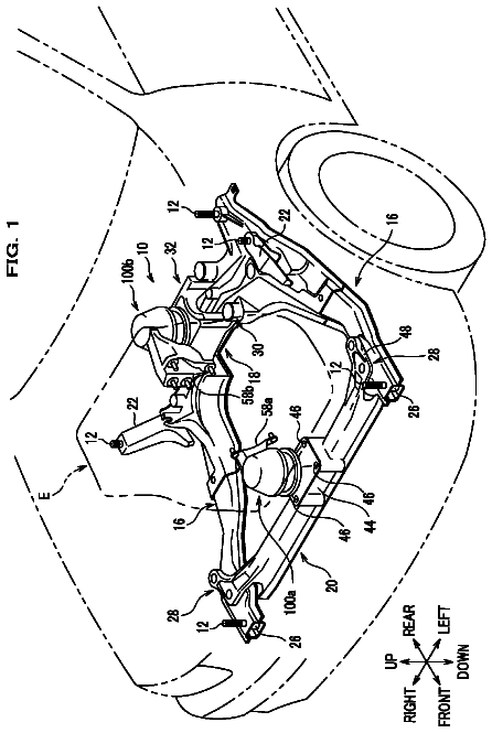
FIG. 1 is a perspective view of a vehicle body front part structure provided with a subframe according to the present invention;
FIG. 2 is a bottom view of the subframe shown in FIG. 1 ;
FIG. 3 is a perspective view of the subframe shown in FIG. 1 ;
FIG. 4 is a cross-sectional view taken along line 4 - 4 of FIG. 3 ;
FIG. 5 is a cross-sectional view taken along line 5 - 5 of FIG. 3 ;
FIG. 6 is a view taken in the direction of arrow 6 of FIG. 3 ;
FIG. 7 is a perspective view with parts broken along line 7 - 7 of FIG. 6 ;
FIG. 8 is a view in the direction of arrow 8 of FIG. 3 ;
FIG. 9 is a cross-sectional view taken along line 9 - 9 of FIG. 3 ;
FIG. 10 is a cross-sectional view taken along line 10 - 10 of FIG. 6 ;
FIG. 11A is a cross-sectional view showing a state in which a core is filled in the subframe of FIG. 7 ;
FIG. 11B is a cross-sectional view showing the core filled in the subframe of FIG. 4 ;
FIG. 12A is a cross-sectional view of the core shown in FIG. 11A ;
FIG. 12B is a cross-sectional view of the core shown in FIG. 11B ;
FIG. 13 is a perspective view of a core used for molding the subframe shown in FIG. 1 ;
FIG. 14 is a cross-sectional view illustrative of the manner in which the core broken along line 7 - 7 of FIG. 6 is set in a casting mold;
FIG. 15 is a view showing an example in which the subframe according to the invention is formed by casting;
FIG. 16A is an enlarged view of a portion 16 a shown in FIG. 6 ;
FIG. 16B is a cross-sectional view taken along line 9 b - 9 b of FIG. 16( a ) ;
FIG. 17A is a cross-sectional view taken along line 17 a - 17 a of FIG. 8 ;
FIG. 17B is a cross-sectional view taken along line 17 b - 17 b of FIG. 8 ;
FIG. 18 is a plan view showing a core unit according to the present invention;
FIG. 19 is a bottom view of the core unit shown in FIG. 18 ;
FIG. 20 is a cross-sectional view taken along line 20 - 20 of FIG. 18 ;
FIG. 21 is a cross-sectional view taken along line 21 - 21 of FIG. 19 ;
FIG. 22 is a cross-sectional view taken along line 22 - 22 of FIG. 18 ;
FIG. 23 is a cross-sectional view illustrative of the manner in which a left core is supported by a core print according to the invention; and
FIG. 24 is a cross-sectional view illustrative of the manner in which the left core is supported by a top core holding pin according to the invention.
A certain preferred structural embodiment of the present invention will be described in detail below with reference to the accompanying sheets of drawings. The terms “front (Fr)”, “rear (Rr)”, “left (L)” and “right (R)” are used herein to refer to directions as viewed from a driver. Embodiment
As shown in FIGS. 1 and 2 , a vehicle body front part structure 10 includes left and right side frames 11 and 12 disposed to extend in a front-and-rear or longitudinal direction of a vehicle body, a subframe 15 attached under the left and right side frames 11 , 12 , left and right suspension arms 16 and 17 provided at left and right end portions of the subframe 15 , and left and right suspensions 21 and 22 connected to the left and right suspension arms 16 , 17 .
The vehicle body front part structure 10 further includes a steering gearbox 24 attached to an upper part 15 a of the subframe 15 , and a torque rod 26 interconnecting the subframe 15 and a power plant 25 . A steering shaft 28 extends upwardly from the gearbox 24 , and a steering wheel 29 is connected to an upper end of the steering shaft 28 . The power plant 25 is comprised of an engine-transmission unit disposed in a lateral direction between the left and right side frames 11 , 12 , the engine-transmission unit including an engine and a transmission formed integrally with each other.
As shown in FIGS. 3 and 4 , the subframe 15 is formed from aluminum alloy into a unitary structure having a wall thickness T 1 through a high-pressure casing process using a core unit 200 ( FIGS. 13 and 18 ). The subframe 15 includes a main body or body 32 , a left vehicle-body attachment portion 34 and a left suspension support portion 35 that are provided at a left end 32 a of the body 32 , a right vehicle body attachment portion 36 and a right suspension support portion 37 that are provided at right end 32 b of the body 32 , and a central connecting portion 38 provided at a front central part of the body 32 (for connection with a connecting member).
The left vehicle-body attachment portion 34 includes a left front attachment portion 34 a provided at a front part 32 c of the left end 32 a of the body 32 , and a left rear attachment portion 34 b provided at a rear part 32 d of the left end 32 a of the body 32 . Like the left vehicle-body attachment portion 34 , the right vehicle-body attachment portion 36 includes a right front attachment portion 36 a provided at a front part 32 e of the right end 32 b of the body 32 , and a right rear attachment portion 36 b provided at a rear part 32 f of the right end 32 b of the body 32 .
The left front attachment portion 34 a and the left rear attachment portion 34 b are bolted to the left side frame 11 ( FIG. 1 ). Similarly, the right front attachment portion 36 a and the right rear attachment portion 36 b are bolted to the right side frame 12 ( FIG. 1 ). Thus, the subframe 15 is attached crosswise between the left and right side frames 11 , 12 , as shown in FIG. 1 .
Referring again to FIGS. 3 and 4 , the body 32 includes a top or top wall 41 on an upper side thereof, a bottom or bottom wall 42 on a lower side thereof, a front wall 43 connecting front ends of the top wall 41 and the bottom wall 42 , and a rear wall 44 connecting rear ends of the top wall 41 and the bottom wall 42 . The body 32 has a hollow part 45 formed jointly by the top wall 41 , the bottom wall 42 , the front wall 43 and the rear wall 44 . The top wall 41 and the bottom wall 42 are spaced from each other in a vertical direction at a predetermined interval.
The top wall 41 has a plurality of upper holding pin holes 47 formed along an outer periphery 41 thereof (only those upper holding pin holes 47 which are formed along a front part of the outer periphery 41 being shown). The upper holding pin holes 47 are formed by a corresponding number of top core holding pins (core support portions) 253 ( FIG. 24 ) used for supporting the core unit 200 during cast-molding.
The top wall 41 includes a plurality of top longitudinal ribs 48 ( FIG. 6 ) and a plurality of top lateral ribs 49 that are provided on an inner surface 41 d of the top wall 41 for reinforcing the subframe 15 . As shown in FIGS. 5 and 6 , the top longitudinal ribs 48 project from the inner surface 41 d into the hollow part 45 and extend in the front-and-rear or longitudinal direction of the vehicle. The top lateral ribs 49 protrude from the inner surface 41 d into the hollow part 45 and extend in a width or lateral direction of the vehicle.
The top wall 41 includes a top parallel section 52 formed substantially horizontally at a rear part thereof in the front-and-rear direction of the vehicle, a raised section 53 formed at a front end 52 a of the top parallel section 52 , and a top inclined section 53 obliquely formed at a front end 53 a of the raised section 53 .
The top parallel section 52 has a left top sand eliminating opening (top opening) 56 formed near a left end 52 a thereof, and a right top sand eliminating opening (top opening) 57 formed near a right end 52 b thereof. The left top sand eliminating opening 56 and the right top sand eliminating opening 57 are openings which are provided in order to remove the core unit 200 ( FIG. 13 ) from the hollow part 45 of the subframe 15 to the outside of the subframe 15 .
As shown in FIG. 3 , the top inclined section 54 is provided at a front part of the top wall 41 in the front-and-rear direction of the vehicle, the top inclined section 54 being downward inclined from the rear side of the vehicle to the front side of the vehicle. The top inclined section 54 has a left top inclined opening 58 formed near a left end 54 a thereof located forwardly of the left top sand eliminating opening 56 in the front-and-rear direction of the vehicle, and a right top inclined opening 59 formed near a right end 54 b thereof and located forwardly of the right top sand eliminating opening 57 in the front-and-rear direction of the vehicle.
The left inclined opening 58 and the right inclined opening 59 are two of the plural bottom holding pin holes 47 . To facilitate understanding of the structure, these two pin holes 47 will be described below as being the left and right top inclined openings 58 , 59 .
As shown in FIG. 8 , the bottom wall 42 has a plurality of bottom holding pin holes 62 and a plurality of core print openings 63 formed along an outer periphery 42 c thereof. The lower holding pin holes 62 are formed by a corresponding number of lower core holding pins (core support portions) used for supporting the core unit 200 ( FIG. 13 ) during cast-molding. The core print openings 93 , as shown in FIG. 14 , are formed by a corresponding number of core prints (core supporting portions) 235 ( FIG. 19 ) used for supporting the core unit 200 during cast-molding.
As shown in FIGS. 7 and 8 , the bottom wall 42 has a plurality of bottom longitudinal ribs 66 and a plurality of bottom lateral ribs 67 that are provided on an inner surface 42 d of the bottom wall 42 for reinforcing the subframe 15 . The bottom longitudinal ribs 66 project from the inner surface 42 d into the hollow section 45 and extend in the front-and-rear direction of the vehicle. As shown in FIGS. 5 and 8 , the bottom lateral ribs 67 project from the inner surface 42 d into the hollow section 45 and extend in the width direction of the vehicle.
The bottom wall 42 includes a bottom rear parallel section (bottom parallel section) 71 formed substantially horizontally at a rear part thereof in the front-and-rear direction of the vehicle, a bottom inclined section 72 formed at a front end 71 a of the bottom rear parallel section 71 , and a bottom front parallel section (bottom parallel section) 73 formed substantially horizontally at a front end 72 a of the bottom inclined section 72 . The top parallel section 52 is disposed above the bottom rear parallel section 71 in opposed relation with a prescribed space defined therebetween. The top parallel section 52 and the bottom rear parallel section 71 are formed so as to be substantially parallel to each other in the front-and-rear direction of the vehicle.
As shown in FIG. 8 , the bottom rear parallel section 71 has a left bottom rear sand eliminating opening (bottom opening) 75 formed near a left end 71 b thereof, and a right bottom rear sand eliminating opening (bottom opening) 76 formed near a right end 71 c thereof shown in FIG. 3 . The left bottom rear sand eliminating opening 75 is formed, at a part of the bottom rear parallel section 71 which is opposed to the left top sand eliminating opening 56 , into a shape equivalent to a shape of the left top sand eliminating opening 56 . The right bottom rear sand eliminating opening 76 is formed, at a part of the bottom rear parallel section 71 which is opposed to the right top sand eliminating opening 57 , into a shape equivalent to a shape of the right top sand eliminating opening 57 . Like the left and right top sand eliminating openings 56 , 57 , the left and right bottom rear sand eliminating openings 75 , 76 are openings which are provided in order to remove the core unit 200 from the hollow part 45 of the subframe 15 to the outside of the subframe 15 .
The bottom front parallel section 73 is provided at a part of the bottom wall 42 which is located at a front part of the bottom wall 42 and which is opposed to the top inclined section 54 . The bottom front parallel section 73 is formed substantially horizontally. The bottom front parallel section 73 has a left bottom front sand eliminating opening (front opening) 77 formed near a left end 73 a thereof and located forwardly of the left bottom rear sand eliminating opening 75 in the front-and-rear direction of the vehicle, and a right bottom front sand eliminating opening (front opening) 78 formed near a right end 73 b and located forwardly of the right bottom rear sand eliminating opening 76 in the front-and-rear direction of the vehicle.
The left bottom front sand eliminating opening 77 is formed at a part of the bottom wall 42 (specifically, the bottom front parallel section 73 ) which is opposed to the left top inclined opening 58 ( FIG. 3 ). The right bottom front sand eliminating opening 78 is formed at a part of the bottom wall 42 (specifically, the bottom front parallel section 73 ) which is opposed to the right top inclined opening 59 . The bottom front parallel section 73 is provided at a part of the bottom wall 42 which is located at a front part of the bottom wall 42 and which is opposed to the top inclined section 54 . The bottom front parallel section 73 is formed substantially horizontally. The bottom front parallel section 73 has the right bottom front sand eliminating opening 78 formed near the left end 73 thereof and located forwardly of the left bottom rear sand eliminating opening 75 in the front-and-rear direction of the vehicle. Like the left and right top sand eliminating openings 56 , 57 , the left and right bottom front sand eliminating openings 77 , 78 are openings which are provided in order to remove the core unit 200 ( FIGS. 11A-11B ) from the hollow part 45 of the subframe 15 to the outside of the subframe 15 .
As shown in FIGS. 1 and 2 , the left suspension support portion 35 includes a left front connecting part 81 provided at the front part 32 c of the left end 32 a of the body 32 , and a left rear connecting part 82 provided at the rear part 32 d of the left end 32 a of the body 32 .
The left front connecting part 81 is provided to protrude from the front part 32 c in a forward direction of the vehicle and hence is located forwardly of the left front attachment portion 34 a . The left rear connecting part 82 is provided inwardly of the left rear attachment portion 34 b ( FIG. 3 ) in the vehicle width direction and hence is disposed between the left rear attachment portion 34 b and the rear part 32 d . A front attachment part 16 a of the left suspension arm 16 is connected to the left front connecting part 81 via a left front support pin 84 . A rear attachment part 16 b of the left suspension arm 16 is connected to the left rear connecting part 82 via a left rear support pin.
The left suspension has a lower end 21 a connected to the left suspension arm 16 and an upper end 21 b connected to a left damper housing 13 . The left damper housing 13 is formed integrally with the left side frame 11 . The left suspension 21 is thus supported on the left suspension arm 16 . The left suspension 21 is therefore supported on the left suspension support portion 35 via the left suspension arm 16 .
Like the left suspension support portion 35 , the right suspension support portion 37 includes a right front connecting part 87 provided at the front part 32 e of the right end 32 b of the body 32 , and a right rear connecting part 88 provided at the rear part 32 f of the right end 32 b of the body 32 .
The right front connecting part 87 is provided to protrude from the front part 32 e in a forward direction of the vehicle and hence is located forwardly of the right front attachment portion 36 a . The right rear connecting part 88 is provided inwardly of the right rear attachment portion 36 b ( FIG. 3 ) in the vehicle width direction and hence is disposed between the right rear attachment portion 36 b and the rear part 32 f . A front attachment part 17 a of the right suspension arm 17 is connected to the right front connecting part 87 via a right front support pin 91 . A rear attachment part 17 b of the right suspension arm 17 is connected to the right rear connecting part 88 via a right rear support pin.
The right suspension arm 17 is a member which is substantially bilaterally symmetrical with the left suspension arm 16 . A lower end 22 a of the right suspension 22 is connected to the right suspension arm 17 , and an upper end 22 a of the right suspension 22 is connected to a right damper housing 14 . The right damper housing 14 is formed integrally with the right side frame 12 . The right suspension 22 is thus supported on the right suspension support portion 37 via the right suspension arm 17 .
As shown in FIGS. 2 and 3 , the central connecting portion 38 is provided at a center in the vehicle width direction of the body 32 and located in a front half of the body 32 (i.e., a front portion in the front-and-rear direction of the vehicle). The torque rod 26 has a proximal end 26 a connected to the central connecting portion 38 by a bolt 51 ( FIG. 1 ) and a nut 52 . Thus, the power plant 25 is supported by the torque rod 26 .
Next, the top longitudinal ribs 48 and the top lateral ribs 49 that are provided on the body 32 (top wall 41 ) and the bottom longitudinal ribs 66 and the bottom lateral ribs 67 that are provided on the body 32 (bottom wall 42 ) will be described in greater detail.
As shown in FIG. 6 , the top longitudinal ribs 48 include a left outer top longitudinal rib 48 a and a left inner top longitudinal rib 48 b which are provided at a left end portion 41 e of the top wall 41 , and a right outer top longitudinal rib 48 c and a right inner longitudinal rib 48 d which are provided at a right end portion 41 f of the top wall 41 . These top longitudinal ribs 48 a - 48 d extend in the front-and-rear or longitudinal direction of the vehicle.
The left outer top longitudinal rib 48 a is provided at a front part 41 g of the left end portion 41 e of the top wall 41 which is adjacent to the left suspension support portion 35 (left front connecting part 81 ), the left outer top longitudinal rib 48 a extending from the front part 41 g to a rear part 41 h of the left end portion 41 e of the top wall 41 in a rearward direction of the vehicle. The left outer top longitudinal rib 48 a intersects with a left front top lateral rib 49 a and a left rear top lateral rib 49 b.
The left inner top longitudinal rib 48 b is provided at a part 41 i of the left end portion 41 e of the top wall 41 which is adjacent to the left suspension support portion 35 (left front connecting part 81 ) and which is located inwardly of the left outer top longitudinal rib 48 a in the vehicle width direction. The right outer top longitudinal rib 48 c and the right inner top longitudinal rib 48 d are members which are laterally symmetrical with the left outer top longitudinal rib 48 a and the left inner top longitudinal ribs 48 b , respectively, and a detailed description of these members can be omitted.
The top lateral ribs 49 include the left front top lateral rib 49 a provided at the part 41 g of the top wall 41 (left end portion 41 e ) which is adjacent to the left front connecting part 81 , the left rear top lateral rib 49 b disposed rearwardly of the left front top lateral rib 49 a in the front-and-rear direction of the vehicle, a right front top lateral rib 49 c provided at the right connecting part 87 of the top wall 41 (right end portion 41 f ), and a right rear top lateral rib 49 d disposed rearwardly of the right front top lateral rib 49 in the front-and-rear direction of the vehicle. These top lateral ribs 49 a - 49 d extend in the vehicle width direction.
The left front top lateral rib 49 a is provided at the part 41 g of the left and portion 41 e of the top wall 41 which is adjacent to the left suspension support portion 35 (left front connecting part 81 ). More specifically, the left front top lateral rib 49 a is provided at a section of the part 41 g which is separated from the front wall 43 in a rearward direction of the vehicle. In other words, the left front top lateral rib 49 a is a rib which extends parallel to the left rear top lateral rib 49 b and which is spaced at a predetermined distance from the left rear top lateral rib 49 b in the rearward direction of the vehicle. The left front top lateral rib 49 a and the left outer top longitudinal rib 48 a cross each other at a top intersection 93 .
The left rear top lateral rib 49 b is provided at a part 41 j of the left end portion 41 e of the top wall 41 which is adjacent to the left suspension support portion 35 (left front connection part 81 ) and which is rearward of the left front top lateral rib 49 a in the front-and-rear direction of the vehicle. The left rear top lateral rib 49 b extends from the part 41 j to a laterally central portion 41 k in the vehicle width direction. The left rear top lateral rib 49 b and the left outer top longitudinal rib 45 a cross each other at a top outer intersection 94 , and the left rear top lateral rib 49 b and the left inner top longitudinal rib 49 b cross each other at a top inner intersection 95 .
In other words, the left rear top lateral rib 49 b extends from the central connecting portion 38 toward a lateral outward portion of the body 32 . Specifically, the left rear top lateral rib 49 b extends from the central connecting portion 38 in a lateral outward direction of the vehicle toward the left suspension support portion 35 . With this arrangement, a load inputted to the central connecting portion 38 and a load inputted to the left suspension support portion 35 can be efficiently supported or borne by the left rear top lateral rib 49 b , and sufficient rigidity and strength of the subframe 15 can be ensured.
Furthermore, the upper holding pin hole 47 (represented by reference character 47 A for easy understanding), which is formed by the top core holding pin 253 ( FIG. 24 ) used for supporting the core unit 200 ( FIG. 18 ), is disposed near the left rear top lateral rib 49 b . With this arrangement, the rib 49 b is able to prevent the upper holding pin hole 47 A from forming a starting point of stress concentration when the upper holding pin hole 47 A is subjected to a load. Thus, the upper holding pin hole 47 A formed by the top core holding pin 253 can never lead to a reduction in the rigidity and strength of the subframe 15 .
By virtue of the left rear top lateral rib 49 b provided for reinforcing the upper holding pin hole 47 A, it is possible to provide the top core holding pin 253 ( FIG. 24 ) at a position adjacent to the left suspension support portion 35 . The top core holding pin 253 can thus be located at an appropriate position. This will ensure that in the production of the subframe 15 by cast-molding, the core unit 200 ( FIG. 18 ) can be properly supported by the top core holding pin 253 so that a produced subframe 12 has a uniform wall thickness.
The left rear top lateral rib 49 b and the left outer top longitudinal rib 48 a cross each other at the top outer intersection 94 , and the left rear top lateral rib 49 b and the left inner top longitudinal rib 48 b cross each other at the top inner intersection 95 . The right front top lateral rib 49 c and the right rear top lateral rib 49 d are members which are laterally symmetrical with the left front top lateral rib 49 a and the left rear top lateral rib 49 b , respectively, and a detailed description of these members can be omitted.
As shown in FIGS. 8 and 9 , the bottom longitudinal ribs 66 include a left outer bottom longitudinal rib 66 a provided at a left end portion 42 e of the bottom wall 42 , a left inner bottom longitudinal rib 66 b provided inwardly of the left outer bottom longitudinal rib 66 a in the vehicle width direction, a right outer bottom longitudinal rib 66 c provided at a right end portion 42 f of the bottom wall 42 , and a right inner bottom longitudinal rib 66 d provided inwardly of the right outer bottom longitudinal ribs 66 c in the vehicle width direction. These ribs 66 a - 66 d extend in the front-and-rear or longitudinal direction of the vehicle.
The left outer bottom longitudinal rib 66 a is provided at a front part 42 g of the left end portion 42 e of the bottom wall 42 which is adjacent to the left suspension support portion 35 (left front connecting part 81 ), the left outer bottom longitudinal rib 66 a extending from the front part 42 g to a rear part 42 h of the left end portion 42 e of the bottom wall 42 in a rearward direction of the vehicle. The left inner bottom longitudinal rib 66 b is provided inwardly of the left outer bottom longitudinal rib 66 a in the vehicle width direction and located near a central area 42 k in the vehicle width direction (which is adjacent to the central connecting portion 38 ). The left inner bottom longitudinal rib 66 b crosses a left rear bottom lateral rib 67 c and a central bottom lateral rib 61 . The left inner bottom longitudinal rib 66 b is provided inwardly of the left bottom front sand eliminating opening 77 and the left bottom rear sand eliminating opening 75 in the vehicle width direction.
The right outer bottom longitudinal rib 66 c and the right inner bottom longitudinal rib 66 d are members which are laterally symmetrical with the left outer bottom longitudinal rib 66 a and the left inner bottom longitudinal rib 66 b , respectively, and a detailed description of these members can be omitted.
The bottom lateral ribs 67 include a left front bottom lateral rib 67 a provided at the front part 42 g of (the left end portion 42 e ) of the bottom wall 42 , a left central bottom lateral rib 67 b disposed rearwardly of the left front bottom lateral rib 67 a in the front-and-rear direction of the vehicle, the left rear bottom lateral rib 67 c disposed rearwardly of the left central bottom lateral rib 67 b in the front-and-rear direction of the vehicle, a right front bottom lateral rib 67 d disposed at a front part 42 i of (the right end portion 42 f ) of the bottom wall 42 , a right central bottom lateral rib 67 e disposed rearwardly of the right front bottom lateral rib 67 d in the front-and-rear direction of the vehicle, and a right rear bottom lateral rib 67 f disposed rearwardly of the right central bottom lateral rib 67 e in the front-and-rear direction of the vehicle. These bottom lateral ribs 67 a - 67 f extend in the lateral or width direction of the vehicle.
The left front lateral rib 67 a is provided at the front part 42 e of the left end portion 42 e of the bottom wall 42 which is adjacent to the left suspension support portion 35 (left front connecting part 81 ) and which is slightly spaced from the front wall 43 in the rearward direction of the vehicle. The left front bottom rib 67 a and the left outer bottom longitudinal rib 66 a cross each other at a bottom front intersection 68 .
The left central bottom lateral rib 67 b is disposed at a part 42 j of the left end portion 42 e of the bottom wall 42 which is adjacent to the left suspension support portion 35 (left front connecting part 81 ) and which is rearward of the left front bottom rib 67 a in the front-and-rear direction of the vehicle. The left central bottom lateral rib 67 b extends from the part 42 j of the left end portion 42 e to the vicinity of the central area 42 k ( FIG. 9 ) in the vehicle width direction. The left central bottom lateral rib 67 b and the left outer bottom longitudinal rib 66 a cross each other at a bottom central outer intersection 69 . The left central bottom lateral rib 67 b and the left inner bottom longitudinal rib 66 b cross each other at a bottom central inner intersection 97 .
The left rear bottom lateral rib 67 c is provided at a part 42 l which is offset from the left central bottom lateral rib 67 in a rearward direction of the vehicle. Furthermore, the left rear bottom lateral rib 67 c extends from the part 42 l to the vicinity of the central area 42 k in the vehicle width direction. In other words, the left rear bottom lateral rib 67 c extends from the central connecting portion 38 in a lateral outward direction of the body 32 . The left outer bottom lateral rib 67 c and the left outer bottom longitudinal rib 66 a cross each other at a bottom rear outer intersection 98 . The left rear bottom lateral rib 67 c and the left inner bottom longitudinal rib 66 b cross each other at a bottom rear inner intersection 99 . With this arrangement, a load inputted to the central connecting portion 38 can be efficiently supported by the left rear bottom lateral rib 67 c , and sufficient rigidity and strength of the subframe 15 can be ensured.
The description continues in the full USPTO document.
About 7,416 words. The USPTO PDF has it with every drawing.
Fees are due 3.5, 7.5 and 11.5 years after grant. This patent expired on October 3, 2025, so the fee marked "not paid" was the one that went unpaid.
VEHICLE SUBFRAME
Filed Apr 2014 · published Mar 2016Vehicle subframe
Filed Apr 2014 · granted Oct 2017Earlier publications, parents and continuations. None of them can still be enforced, or this patent would not be listed.
Prior art cited by the examiner or applicant. Useful when you check your own idea for novelty.
Everything on this page comes from the documents linked above.