Lapsed, fee not paid28 drawings
Vehicles & Drones · US 9,776,570 B2
Work vehicle
The purpose of the present invention is to provide a work vehicle with which convenience during boarding/alighting can be improved.
US 9,776,578 B2 · Assignee: TOYOTA JIDOSHA KABUSHIKI KAISHA · Inventors: Yamamoto; Kazuhito
Sheet 1 of 13 from the published document. All sheets in the USPTO PDF
The clip includes a first engagement hook and a second engagement hook. The first engagement hook engages the body when the clip is in a normal fitting with the body. The second engagement hook prevents the clip from being disengaged from the body when the first engagement hook has been disengaged from the body. When the first engagement hook is disengaged from the body, a member is lifted away from surrounding members to such an extent as can be recognized by sight. Therefore, a state that the clip is not in the normal fitting state with the body is noticeable. Even if the clip is coupled to the body in the non-fitting state or half-fitting state, the second engagement hook prevents the clip from being disengaged from the body.
Patent Documents 1 and 2 below disclose a clip for fixing a pillar garnish, which is a member, to a pillar, which is a body. The conventional clip has one kind of engagement hook. Even if the one kind of engagement hook includes a pair of engagement hooks, the positions of the engagement hooks are equal to each other in an axial direction of the clip. Only when the clip is in a normal fitting with the body can the member be installed on the body at a normal fixing position.
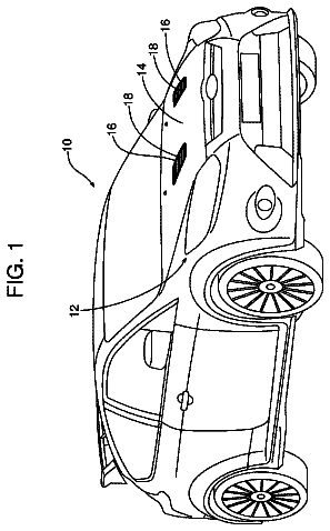
1 of 13 drawing sheets so far from the published document, cropped to the drawing. Every sheet is in the USPTO PDF.
What the patent claimed, word for word. All of it is now free to use.
This application relates to a clip and a pillar garnish fixing structure using the clip. In the descriptions below, the words “structure” and “fix” may be replaced by “apparatus” and “mount,” respectively.
Patent Documents 1 and 2 below disclose a clip for fixing a pillar garnish, which is a member, to a pillar, which is a body. The conventional clip has one kind of engagement hook. Even if the one kind of engagement hook includes a pair of engagement hooks, the positions of the engagement hooks are equal to each other in an axial direction of the clip. Only when the clip is in a normal fitting with the body can the member be installed on the body at a normal fixing position.
Patent Document 1: Patent Publication JP 2013-113419
Patent Document 2: Patent Publication JP 2013-180725 BRIEF SUMMARY
However, there are the following problems with the conventional clip:
A first problem is that a difference between a position of the member relative to the body when the clip is in a normal fitting with the body and a position of the member relative to the body when the clip is in a non-fitting state or a half-fitting state with the body is small. Even if the member looks as if it is fixed to the body, there is a possibility that the clip is in a non-fitting state or a half-fitting state with the body. Here, a “normal fitting” state is defined as a state where a shaft of the clip is inserted into a body engagement aperture of the body, and all engagement hooks are brought into engagement with a back surface of a rim that defines the body engagement aperture. Further, a “non-fitting” state is defined as a state where any of the engagement hooks is not in engagement with the back surface of the body, and a “half-fitting” state is defined as a state where one of paired engagement hooks is in engagement with the back surface of the body while the other of the paired hooks is not in engagement with the back surface of the body.
A second problem is that the clip only fixes the member to the body at a normal fixing position when the clip is in the normal fitting with the body. As a result, in a case where the clip has been fitted to the body at a non-fitting state or a half-fitting state, when a large external load is loaded on the clip or the member, there is a possibility that the member is removed from the body together with the clip.
An object of the application is to provide a clip and a pillar garnish fixing structure using the clip. According to the application, even if the clip has been fixed to a body in a non-fitting state or a half-fitting state, the state can be easily recognized from an external appearance of the member, and even if the clip has been fixed to the body in a non-fitting state or a half-fitting state with the body, inadvertent removal of the clip from the body can be prevented. Means for Solving the Problem
A clip and a pillar garnish fixing structure according to the present application for achieving the above object can take the aspects or embodiments described below. In this connection, reference numerals in brackets correspond to reference numerals shown in the accompanying drawings.
In a first aspect of the present application, a clip ( 10 ) is used for fixing a member ( 80 ) to a body ( 90 ) at a body engagement aperture ( 92 ).
The clip ( 10 ) includes: a first engagement hook ( 40 ) that is configured to engage with a rim defining a body engagement aperture ( 92 ) when the clip ( 10 ) is in a normal fitting with the body ( 90 ); and a second engagement hook ( 60 ) spaced from the rim defining the body engagement aperture ( 92 ) when the clip ( 10 ) is in the normal fitting with the body ( 90 ). The second engagement hook ( 60 ) is brought into engagement with the rim defining the body engagement aperture ( 92 ) when the first engagement hook ( 40 ) has been disengaged from the body ( 90 ), thereby preventing the clip ( 10 ) from being removed from the body ( 90 ).
The second engagement hook ( 60 ) is located at a position deeper than the first engagement hook ( 40 ) in an inserting direction of the clip into the body engagement aperture ( 92 ).
In the first aspect of the present application, the clip ( 10 ) further includes a seat ( 20 ) and a shaft ( 22 ) extending in a direction away from the seat ( 20 ). Paired first engagement hooks ( 40 ) each constructed from the first engagement hook are provided at the shaft ( 22 ) such that the paired first engagement hooks ( 40 ) are opposed to each other in a direction perpendicular to a center axis line ( 10 a ) of the clip. An opening ( 26 ) is provided at the shaft ( 22 ) so as to penetrate the shaft ( 22 ) in a direction perpendicular to the direction in which the paired first engagement hooks ( 40 ) are opposed.
The second engagement hook ( 60 ) is disposed in the opening ( 26 ) such that the second engagement hook ( 60 ) is elastically deformable in the direction perpendicular to the direction in which the paired first engagement hooks ( 40 ) are opposed.
In a second aspect of the present application, the clip ( 10 ) further includes an engagement releasing portion ( 68 ).
The engagement releasing portion ( 68 ) includes a connecting end ( 68 a ) located at a first end of the engagement releasing portion ( 68 ) and a handling portion ( 68 b ) located at a second, opposite end of the engagement releasing portion ( 68 ). The engagement releasing portion ( 68 ) is connected to the second engagement hook ( 60 ) at the connecting end ( 68 a ). The handling portion ( 68 b ) is provided such that the handling portion ( 68 b ) is accessible when the clip ( 10 ) is removed from the body ( 90 ).
In a third aspect of the present application, the engagement releasing portion ( 68 ) includes an intermediate portion ( 68 c ) having a deformability and formed as a strap. The intermediate portion ( 68 c ) extends between the connecting end ( 68 a ) and the handling portion ( 68 b ). The intermediate portion ( 68 c ) extends from a side closer to a tip of the shaft ( 22 ) than the body ( 90 ), through the body engagement aperture ( 92 ), to a side closer to the seat ( 20 ) than the body ( 90 ), when the clip ( 10 ) is in the normal fitting with the body ( 90 ).
In a fourth aspect of the present application, the handling portion ( 68 b ) of the engagement releasing portion ( 68 ) includes a portion located outside a configuration of the seat ( 20 ).
In a fifth aspect of the present application, the seat ( 20 ) has a groove ( 20 a ) formed at a portion of the seat ( 20 ) with which the handling portion ( 68 b ) of the engagement releasing portion ( 68 ) interferes when the clip ( 10 ) is in the normal fitting with the body ( 90 ). The groove ( 20 a ) is open to an outside of the seat at a laterally outside surface and axially opposite surfaces of the seat ( 20 ). The engagement releasing portion ( 68 ) extends through the groove ( 20 a ) of the seat.
In a sixth aspect of the present application, the member ( 80 ) includes a rack portion ( 82 ). The handling portion ( 68 b ) of the engagement releasing portion ( 68 ) is located between the rack portion ( 82 ) and the body ( 90 ) when the clip ( 10 ) is in the normal fitting with the body ( 90 ).
In a seventh aspect of the present application, the clip ( 1 ) further includes a deformable connecting portion ( 66 ). The second engagement hook ( 60 ) is connected via the deformable connecting portion ( 66 ) to a tip ( 24 ) of the shaft located farther from the seat ( 20 ) than the opening ( 26 ).
In an eighth aspect of the present application, the deformable connecting portion ( 66 ) is formed as a plate having a cross section, a thickness of which extends in the direction perpendicular to the direction in which the paired first engagement hooks ( 40 ) are opposed and a width of which extends in the direction in which the paired first engagement hooks ( 40 ) are opposed. The thickness is selected to be smaller than the width. The second engagement hook ( 60 ) can be elastically displaced in the direction perpendicular to the direction in which the paired first engagement hooks ( 40 ) are opposed.
In a ninth aspect of the present application, the second engagement hook ( 60 ) is constructed to be able to take three positions including an inclined position (A), an erected position (B) more erected than the inclined position (A), and a lateral position (C) more lateral than the inclined position (A). The second engagement hook ( 60 ) is constructed so as to be able to be displaced over the three positions.
At the inclined position (A), only one end portion ( 62 ) of the second engagement hook ( 60 ) is located at a position more outward than a position corresponding to an inner diameter of the body engagement aperture ( 92 ).
At the erected position (B), an entirety of the second engagement hook ( 60 ) is located at a position equal to or more inward than the position corresponding to the inner diameter of the body engagement aperture ( 92 ).
At the lateral position (C), at least one end portion ( 62 , 64 ) of the second engagement hook ( 60 ) is located at a position more outward than the position corresponding to the inner diameter of the body engagement aperture ( 92 ).
In a tenth aspect of the present application, when no load is loaded on the deformable connecting portion ( 66 ) at an early stage of insertion of the clip ( 10 ) into the body engagement aperture ( 92 ), the second engagement hook ( 60 ) takes the inclined position (A).
When the second engagement hook ( 60 ) is passing through the body engagement aperture ( 92 ) on a way of insertion of the clip ( 10 ) into the body engagement aperture ( 92 ), the second engagement hook ( 60 ) takes the erected position (B).
When the second engagement hook ( 60 ) has passed through the body engagement aperture ( 92 ), then the first engagement hook ( 40 ) is brought into engagement with the rim defining the body engagement aperture ( 92 ), and the second engagement hook ( 60 ) elastically returns to a free state of the second engagement hook, the second engagement hook ( 60 ) takes the inclined position (A).
When a pulling force is loaded on the engagement releasing portion ( 68 ) when removing the clip ( 10 ) from the body ( 90 ) at a time of service, the second engagement hook ( 60 ) takes the erected position (B).
When a pushing load is loaded on the deformable connecting portion ( 60 ) after the second engagement hook ( 60 ) has elastically returned to the free state, the second engagement hook ( 60 ) takes the lateral position (C).
In an eleventh aspect of the present application, when the second engagement hook ( 60 ) takes the lateral position (C), opposite end portions ( 62 , 64 ) of the second engagement hook ( 60 ) are located more outward than the position corresponding to the inner diameter of the body engagement aperture ( 92 ).
In a twelfth aspect of the present application, in a state that the second engagement hook ( 60 ) is at the inclined position (A), the connecting end ( 68 a ) of the engagement releasing portion ( 68 ) with the second engagement hook ( 60 ) is located closer to the only one end portion ( 62 ) of the second engagement hook ( 60 ) than a connecting portion of the second engagement hook ( 60 ) with the deformable connecting portion ( 66 ).
In a thirteenth aspect of the present application, the first engagement hook ( 40 ) is connected to the shaft ( 22 ) at a hook connecting portion ( 42 ) spaced from the seat ( 20 ) and extends from the hook connecting portion ( 42 ) toward the seat ( 20 ) to end in a form of a free end. The first engagement hook ( 40 ) is separated from the shaft ( 22 ) except at the hook connecting portion ( 42 ).
The first engagement hook ( 40 ) includes a sliding-contact surface ( 46 ) and an engagement surface ( 48 ). The sliding-contact surface ( 46 ) is brought into sliding-contact with an inside surface of the body engagement aperture ( 92 ) when the clip ( 10 ) passes through the body engagement aperture ( 92 ). The engagement surface ( 48 ) is brought into engagement with the rim defining the body engagement aperture ( 92 ) in an axial direction of the clip when the clip ( 10 ) has been installed to the body ( 90 ).
The first engagement hook ( 40 ) takes two positions including an outer position (D) and an inner position (E) and is elastically deformable between the two positions. At the outer position (D), the engagement surface ( 48 ) of the first engagement hook ( 40 ) is located at a position equal to or more outward than a position of an inner diameter of the body engagement aperture ( 92 ) in a diametrical direction of the body engagement aperture ( 92 ). At the inner position (E), the sliding-contact surface ( 46 ) is located at a position equal to or more inward than the position of the inner diameter of the body engagement aperture ( 92 ) in the diametrical direction of the body engagement aperture ( 92 ).
In a fourteenth aspect of the present application, the clip ( 10 ) is a tether clip including a tether ( 70 ) which has an anchor ( 70 b ) at a tip of the tether.
In a fifteenth aspect of the present application, the tether ( 70 ) of the tether clip ( 10 ) is curved in a direction parallel to or perpendicular to a longitudinal direction of the member ( 80 ). The engagement releasing portion ( 68 ) is curved in the same direction as the direction in which the tether ( 70 ) is curved.
In a pillar garnish fixing structure ( 1 ) according to a sixteenth aspect of the present application, the member ( 80 ) is a pillar garnish and the body ( 90 ) is a pillar panel of a vehicle, and the pillar garnish ( 80 ) is installed to the pillar panel ( 90 ) using the tether clip ( 10 ) according to the fourteenth aspect.
According to the first aspect, the following technical advantages are obtained: since the second engagement hook is provided so as to be located deeper (i.e., closer to the tip of the shaft of the clip) than the first engagement hook in an inserting direction of the clip into the body engagement aperture, when the first engagement hook has been disengaged from the body due to a non-fitting or half-fitting of the first engagement hook with the body, the second engagement hook is brought into engagement with a back surface of the body. In that case, the member is lifted away from surrounding members to an extent that the amount that is lifted away can be recognized by sight. As a result, it is easily recognized from an external appearance that the clip is in the non-fitting or half-fitting with the body. Therefore, overlooking that the clip is not in the normal fitting with the body is prevented or substantially prevented from happening. Further, even if the clip has been coupled to the body in the non-fitting or half-fitting with the body, removal of the clip and the member from the body can be prevented from happening by the second engagement hook.
Further, since the second engagement hook is disposed so as to be deformable in the opening of the shaft, the second engagement hook can take a position where the second engagement hook is housed in the opening and another position where at least an end portion of the second engagement hook is located outside the opening. By taking the position where the second engagement hook is housed in the opening, the second engagement hook can pass through the body engagement aperture when the clip is inserted into the body engagement aperture or when the clip is removed from the body through the body engagement aperture. Further, by taking the position where at least an end portion of the second engagement hook is located outside the opening, even when the first engagement hook is disengaged from the body, the second engagement hook can be engaged with the rim defining the body engagement aperture, thereby preventing the clip from being removed from the body. Further, since the second engagement hook is elastically deformable in the direction in which the paired first engagement hooks are opposed, the second engagement hook can be displaced independently of the deformation of the paired first engagement hooks.
According to the second aspect, since the clip includes the engagement releasing portion, by pulling the engagement releasing portion, the second engagement hook can be displaced so that the clip can be removed from the body. As a result, removability of the clip at a time of service can be improved. Further, since the handling portion of the engagement releasing portion is disposed at an accessible place, access to the handling portion at the time of service is easy.
According to the third aspect, since the intermediate portion of the engagement releasing portion extends towards a seat side through the body engagement aperture, the engagement releasing portion can be led from a shaft side (access to which is difficult) to the seat side (to which access is possible), so that the handling portion of the engagement releasing portion can be placed at a position to which access is easy.
According to the fourth aspect, since the handling portion of the engagement releasing portion includes a portion located outside the configuration of the seat, the handling portion of the engagement releasing portion can be handled by fingers or a jig without being hindered by the seat.
According to the fifth aspect, since the engagement releasing portion extends through the groove of the seat to the handling portion of the engagement releasing portion, the handling portion of the engagement releasing portion can be handled by fingers or a jig without being hindered by the seat, so that handling the engagement releasing portion is easy.
According to the sixth aspect, since the handling portion of the engagement releasing portion is located between the rack portion of the member and the body (unlike a case where the handling portion is located inside a rack portion or is located deeper than the body), access to the handling portion is possible when the member is lifted away from the body.
According to the seventh aspect, since the second engagement hook is connected to the tip portion of the shaft via the deformable connecting portion, the second engagement hook can be elastically displaced relative to the shaft. As a result, by pulling the engagement releasing portion, the second engagement hook can be changed in position. Further, the clip may be formed integrally with the second engagement hook by injection molding.
According to the eighth aspect, since the thickness of the deformable connecting portion in the direction perpendicular to the direction in which the paired first engagement hooks are opposed is smaller than the width of the deformable connecting portion in the direction in which the paired first engagement hooks are opposed, the second engagement hook can be elastically displaced in the direction perpendicular to the direction in which the paired first engagement hooks are opposed.
According to the ninth aspect, when the second engagement hook is in the inclined position, only one end portion of the second engagement hook is located at a position that is more outward than a position corresponding to an inner diameter of the body engagement aperture. Therefore, even if the first engagement hook is disengaged from the body, removal of the clip from the body can be prevented by the second engagement hook. When the second engagement hook is in the erected position, an entirety of the second engagement hook is located at a position equal to or more inward than the position corresponding to the inner diameter of the body engagement aperture. Therefore, the second engagement hook can pass through the body engagement aperture. As a result, fixing the clip to the body and removing the clip from the body are easy. Since a load at a time of fixing the clip to the body and removing the clip from the body becomes small, any damage that may be incurred by the clip at the times of fixing and removing is decreased, so that the clip can be used again. When the second engagement hook is in the lateral position, at least one end portion of the second engagement hook is located at a position more outward than the position corresponding to the inner diameter of the body engagement aperture. Therefore, even if a large load is loaded on the second engagement hook, the second engagement hook can endure the load and prevents the clip from being removed from the body.
According to the tenth aspect, the following technical advantages are obtained: At an early stage of insertion of the clip into the body engagement aperture, the second engagement hook takes the inclined position. Therefore, the clip can be inserted into the body engagement aperture at a light force until the second engagement hook is brought into contact with the rim defining the body engagement aperture. When the second engagement hook is passing through the body engagement aperture on a way of insertion of the clip into the body engagement aperture, the second engagement hook takes the erected position. Therefore, the second engagement hook can pass through the body engagement aperture.
When the second engagement hook has elastically returned to a free state after the second engagement hook has passed through the body engagement aperture, the second engagement hook takes the inclined position. Therefore, even if the first engagement hook is in a non-fitting state or half-fitting state with the rim defining the body engagement aperture, removal of the clip from the rim defining the body engagement aperture can be prevented by the second engagement hook.
When a pulling force is loaded on the engagement releasing portion when removing the clip from the body at a time of service, the second engagement hook takes the erected position. Therefore, the second engagement hook can pass through the body engagement aperture, so that removal of the clip from the rim defining the body engagement aperture is easy.
When a pushing force is loaded on the deformable connecting portion after the second engagement hook has elastically returned to the free state, the second engagement hook takes the lateral position. Therefore, removal of the clip from the rim defining the body engagement aperture can be prevented.
According to the eleventh aspect, when the second engagement hook takes the lateral position, opposite end portions of the second engagement hook are located at a position more outward than the position corresponding to the inner diameter of the body engagement aperture. Therefore, the opposite end portions of the second engagement hook engage the rim defining the body engagement aperture, so that removal of the clip from the rim defining the body engagement aperture can be surely prevented.
According to the twelfth aspect, the connecting end of the engagement releasing portion with the second engagement hook is located closer to the only one end portion of the second engagement hook than the connecting portion of the second engagement hook with the deformable connecting portion. Therefore, when the engagement releasing portion is pulled, the second engagement hook can easily take the erected position.
According to the thirteenth aspect, since the first engagement hook can take the inner position, the first engagement hook can pass through the body engagement aperture by taking the inner position.
Further, since the first engagement hook can take the outer position, the first engagement hook can engage the back surface of the rim defining the body engagement aperture by taking the outer position. When the engagement surfaces of all first engagement hooks are brought into engagement with the back surface of the rim defining the body engagement aperture, the clip is in the normal fitting state with the body.
According to the fourteenth aspect, since the clip is a tether clip, the conventional tether clip can be replaced by the clip according to the present invention, so that a non-fitting state or a half-fitting state of the tether clip with the body and disengagement of the tether clip from the body due to the non-fitting or half-fitting can be suppressed.
According to the fifteenth aspect, since the engagement releasing portion is curved in the same direction as the direction in which the tether is curved, the handling portion of the engagement releasing portion does not receive a pulling force from a curtain airbag when the curtain airbag is developed, so that the second engagement hook is not disengaged from the body.
According to the pillar garnish fixing structure according to the seventeenth aspect, a non-fitting or half-fitting of the clip with the body and free movement of the pillar garnish into a passenger room of a vehicle due to the non-fitting or half-fitting can be suppressed.
FIG. 1 is a perspective view of a clip according to one embodiment of the present invention viewed in a certain direction;
FIG. 2 is a perspective view of the clip of FIG. 1 viewed in a direction different from the direction of FIG. 1 ;
FIG. 3 is a perspective view of the clip of FIG. 1 viewed in a direction different from the directions of FIG. 1 and FIG. 2 ;
FIG. 4 is a cross-sectional view of the clip of FIG. 1 at several stages of insertion of the clip into a body engagement aperture of a body;
FIG. 5 is a cross-sectional view of the clip of FIG. 4 taken along line 5 - 5 of FIG. 4 ;
FIG. 6 is a cross-sectional view of the clip of FIG. 4 at an early stage of insertion of the clip into the body engagement aperture;
FIG. 7 is a cross-sectional view of the clip of FIG. 4 at a time when a second engagement hook is being inserted;
FIG. 8 is a cross-sectional view of the clip of FIG. 4 at a normal time (when the clip is in a normal fitting with the body at a first engagement hook);
FIG. 9 is a cross-sectional view of the clip of FIG. 4 when the clip is being removed from the body;
FIG. 10 is a cross-sectional view of the clip of FIG. 4 when the first engagement hook has disengaged from the body and the second engagement hook has been brought into engagement with the body;
FIG. 11 is a cross-sectional view of the clip of FIG. 4 at a time when a large load has been generated such as a time when a curtain airbag (a curtain shield airbag or briefly, a “CSA”, hereinafter) is being developed;
FIG. 12 is a cross-sectional view of a pillar garnish fixing structure using or including the clip of FIG. 4 ; and
FIG. 13 is a cross-sectional view of the pillar garnish fixing structure of FIG. 12 at a time when the CSA is being developed.
A clip 10 and a pillar garnish fixing structure 1 according to an embodiment of the present invention will be explained with reference to FIGS. 1-13 . A case where the clip 10 is a tether clip, and a pillar garnish is fixed to a body using the tether clip is taken as the embodiment.
Since a main portion of the pillar garnish fixing structure 1 is a clip 10 , the clip 10 and the pillar garnish fixing structure 1 include the same main portion. FIGS. 1-10 illustrate the clip 10 , and FIGS. 12 and 13 illustrate the pillar garnish fixing structure 1 . In FIGS. 12 and 13 , “FR” shows a front direction in a front-rear direction of a vehicle, and “IN” shows an inward direction in a width direction of the vehicle.
<<Structures and Operations>>
First, structures and operations of the clip 10 will be explained. FIGS. 1-13 illustrate that the clip 10 is a tether clip 10 , (where since the tether clip is the same member as the clip, the tether clip is denoted with the same reference numeral as that of the clip). The clip 10 may be a clip other than a tether clip. More particularly, the clip 10 may be a usual clip for fixing a curtain shield airbag (CSA, hereinafter) 88 to a body 90 . The body 90 may be a body (e.g., a body panel such as a pillar panel) of a vehicle or a usual structure other than the body of a vehicle.
The clip 10 is made from a synthetic resin having a deformability. The synthetic resin is, for example, polyamide resin such as polyhexamethylene adipamide. The synthetic resin may be a resin other than polyhexamethylene adipamide so long as the resin has a necessary strength for the clip.
The clip 10 is used for fixing a member 80 to be installed (e.g., a pillar garnish) to a body (e.g., a body panel) 90 at a body engagement aperture 92 formed in the body. The clip 10 includes a first engagement hook 40 and a second engagement hook 60 . The first engagement hook 40 is a hook engaged with a rim that defines the body engagement aperture 92 (a rim defining the body engagement aperture 92 , hereinafter)when the clip 10 is in a normal fitting with the body 90 . The second engagement hook 60 is a hook spaced from the rim defining the body engagement aperture 92 when the clip 10 is in the normal fitting with the body 90 . The second engagement hook 60 is brought into engagement with the rim defining the body engagement aperture 92 when the first engagement hook 40 has been disengaged from the body 90 , thereby preventing the clip 10 from being removed from the body 90 . The second engagement hook 60 is provided at the clip 10 at a position located deeper (closer to a tip of the clip) than the first engagement hook 40 in an inserting direction of the clip 10 into the body engagement aperture 92 .
The clip 10 may be a clip that is removable from the body 90 or a clip that is not removable from the body 90 . In the removable clip, when a certain or large axial load is added to the clip, the first engagement hook 40 is disengaged from the body 90 . The non-removable clip is used as it is in a fitting with the body. An engagement releasing portion 68 described later is provided to the removable clip in the embodiment shown, but the clip provided with the engagement releasing portion 68 may be used as a non-removable clip.
The clip 10 further includes a seat 20 and a shaft 22 extending in a direction away from the seat 20 . The shaft may be called a leg or a fixing portion to the body. The clip 10 includes a center axis line 10 a . The seat 20 is perpendicular to the center axis line 10 a of the clip and the shaft 22 extends on or parallel to the center axis line 10 a of the clip (as shown in FIGS. 4 and 5 ). The shaft 20 includes a tip (or tip portion) 24 spaced from the seat 20 and an opening 26 formed in the shaft 22 between the seat 20 and the tip 24 . The opening 26 penetrates the shaft 22 in a direction perpendicular to the center axis line 10 a of the clip (i.e., in a diametrical direction of the shaft 22 ). A shape of a cross section of the shaft 22 in the direction perpendicular to the center axis line 10 a of the clip may be substantially a circle or a rectangle. The rectangle may include a square. The configuration of the shaft 21 shown in the drawings is a circle.
A configuration of the shaft 22 is smaller than the body engagement aperture 92 , and a configuration of the seat is larger than the body engagement aperture 92 . In a case where the cross section of the shaft 22 is circular and the body engagement aperture 92 is circular, an outside diameter of the shaft 22 is smaller than a diameter of the body engagement aperture 92 . Taking this structure, when the clip 10 is being inserted into the body engagement aperture 92 , the shaft 22 can pass through the body engagement aperture 92 , but the seat 20 can not pass through the body engagement aperture 92 and an insertion movement of the clip 10 stops when or before the seat 20 is brought into contact with the body 90 .
The clip 10 may further include an elastic spacer 74 which is provided on the shaft 22 —side of the seat 20 and is inclined in a direction away from the seat 20 and away from the center axis line 10 a of the clip. The elastic spacer 74 may be formed integrally with the clip 10 as illustrated in FIG. 5 , or may be formed separately from the clip 10 and disposed at a surface of the seat 20 opposite the shaft 22 . A configuration of the elastic spacer 74 is larger than the body engagement aperture 92 . When the clip 10 is being inserted into the body engagement aperture 92 , the rim defining the body engagement aperture 92 is brought into contact with the elastic spacer 74 and deforms the elastic spacer 74 , and then insertion of the clip 10 stops.
At least one first engagement hook 40 is provided. In the embodiment shown, a pair of first engagement hooks 40 is provided. Preferably, paired first engagement hooks 40 (i.e., two first engagement hooks in a pair) are provided. The paired engagement hooks 40 are disposed on opposite sides of the center axis line 10 a of the clip and are opposed to each other. In contrast, only one second engagement hook 60 is provided. The second engagement hook 60 is provided so as to extend in a direction perpendicular to a direction in which the first engagement hooks 40 are opposed.
The first engagement hook 40 is connected to the shaft 22 at a hook connecting portion 42 spaced from 20 and extends from the hook connecting portion 42 toward the seat 20 to end at a free end. The first engagement hook 40 is separated from the shaft 22 except at the hook connecting portion 42 . More particularly, as illustrated in FIG. 5 , a concave portion 28 is formed at a portion of the shaft 22 opposing the first engagement hook 40 , and the first engagement hook 40 is disposed at the concave portion 28 . The first engagement hook 40 is connected to the shaft 22 at the hook connecting portion 42 only, and an inside surface of the first engagement hook 40 is spaced from a surface of the concave portion 28 . This structure may be replaced by another structure where an opening is formed at a wall of the shaft 22 so as to penetrate the wall of the shaft in a thickness direction of the wall, the first engagement hook 40 is disposed in the opening, the first engagement hook 40 is connected to the shaft 22 at the hook connecting portion 42 only, and the first engagement hook 40 is separated from the shaft 22 by only a slit (except at the hook connecting portion 42 ).
The first engagement hook 40 includes a protrusion 44 , a sliding-contact surface 46 and an engagement surface 48 . The protrusion 44 is inclined and extends in a direction away from the hook connecting portion 42 and towards the seat 20 and away from the center axis line 10 a of the clip. The sliding-contact surface 46 is formed at an outside surface of the protrusion 44 . The engagement surface 48 is formed at a surface of the protrusion 44 opposing the seat 20 . The sliding-contact surface 46 is brought into sliding-contact with an inside surface of the body engagement aperture 92 when the clip 10 passes through the body engagement aperture 92 . The engagement surface 48 is brought into engagement with the rim defining the body engagement aperture 92 in an axial direction of the clip when the clip 10 has been installed to the body 90 . The first engagement hook 40 may further include an extended portion 50 extending from an inner end of the engagement surface 48 in a diametrical direction of the clip toward the seat 20 in the axial direction of the clip.
The first engagement hook 40 takes two positions (“position” may be replaced by “attitude”) including an outer position D (a position shown by a full line in a left half of FIG. 5 ) and an inner position E (a position shown by a two-dotted line in a left half of FIG. 5 ) and is elastically deformable to rotate about the hook connecting portion 42 between the two positions. At the outer position D, the engagement surface 48 of the first engagement hook 40 is located at a position equal to or more outward than an inner diameter of the body engagement aperture 92 in a diametrical direction of the body engagement aperture 92 . At the inner position E, the sliding-contact surface 46 is located at a position equal to or more inward than the inner diameter of the body engagement aperture 92 in the diametrical direction of the body engagement aperture 92 .
When the clip 10 is inserted into the body engagement aperture 92 and the first engagement hook 40 passes through the body engagement aperture 92 , the sliding-contact surface 46 is pushed inward by the inside surface of the body engagement aperture 92 . As a result, the first engagement hook 40 takes the inner position E where the sliding-contact surface 46 is located at a position equal to or more inward than the inner diameter of the body engagement aperture 92 so that the first engagement hook 40 can easily pass through the body engagement aperture 92 . Upon having passed through the body engagement aperture 92 , the first engagement hook 40 returns to an original position due to its elasticity. As a result, the first engagement hook 40 takes the outer position D where the engagement surface 48 is located equal to or more outward than an inner diameter of the body engagement aperture 92 so that the engagement surface 48 is engaged with the rim defining the body engagement aperture 92 in the axial direction of the clip.
When the engagement surfaces 48 of all of the first engagement hooks 40 have been engaged with the back surface of the rim defining the body engagement aperture 92 in the axial direction of the clip, the clip 10 is in the normal fitting state with the body 90 . When the clip 10 is in the normal fitting with the body 90 , the rim defining the body engagement aperture 92 is located between the engagement surface 48 of the first engagement hook 40 and the seat 20 and is squeezed between the engagement surface 48 of the first engagement hook 40 and the spacer 74 . At that time, because the spacer 74 is elastically pushed and deformed in the axial direction of the clip 10 , a gap (an axial clearance of the clip) between the engagement surface 48 of the first engagement hook 40 and the body 90 is removed so that movement of the clip 10 relative to the body 90 is suppressed.
In a removable-type clip 10 , it is desirable that the engagement surface 48 of the first engagement hook 40 is inclined so as to extend in a direction from an inner end to an outer end of the engagement surface 48 and away from the seat 20 . Due to this inclination, a removal load that is loaded on the clip 10 from the body engagement aperture 92 —defining rim of the body is more weakened than a case where the engagement surface 48 extends in a direction perpendicular to the center axis line 10 of the clip. As a result, removal of the clip 10 from the rim defining the body engagement aperture 92 at a time of service is possible or easy.
The second engagement hook 60 is disposed in the opening 26 of the shaft 22 . The opening 26 penetrates the shaft 22 in the direction perpendicular to the direction in which the paired first engagement hooks 40 are opposed. The second engagement hook 60 extends along a plane perpendicular to the direction in which the paired first engagement hooks 40 are opposed. The second engagement hook 60 is connected via the deformable connecting portion 66 to the shaft 22 , and more particularly, to the tip 24 of the shaft. The deformable connecting portion 66 is formed integrally with the tip 24 of the shaft 22 and integrally with the second engagement hook 60 . The deformable connecting portion 66 is formed in a form of a plate having a cross section, a thickness of which extends in the direction perpendicular to the direction in which the paired first engagement hooks 40 are opposed (and a width of which extends in the direction in which the paired first engagement hooks 40 are opposed). The thickness of the deformable connecting portion 66 is smaller than the width of the deformable connecting portion 66 so that the second engagement hook 60 can be elastically displaced or is easily displaced in the direction perpendicular to the direction in which the paired first engagement hooks 40 are opposed.
The description continues in the full USPTO document.
About 7,362 words. The USPTO PDF has it with every drawing.
Fees are due 3.5, 7.5 and 11.5 years after grant. This patent expired on October 3, 2025, so the fee marked "not paid" was the one that went unpaid.
GARNISH FIXING STRUCTURE
Filed Jan 2015 · published Dec 2016Clip and pillar garnish fixing structure
Filed Jan 2015 · granted Oct 2017Earlier publications, parents and continuations. None of them can still be enforced, or this patent would not be listed.
Prior art cited by the examiner or applicant. Useful when you check your own idea for novelty.
Everything on this page comes from the documents linked above.