Lapsed, fee not paid3 drawings
Industrial Equipment · US 9,776,435 B2
Elastic roller
An elastic roller includes: a roller shaft; and an elastic member.
US 9,776,447 B2 · Assignee: FUJIFILM Corporation · Inventors: Ikeda; Kimi et al.
Sheet 1 of 2 from the published document. All sheets in the USPTO PDF
Provided is an inkjet recording sheet which includes a transparent support and an ink receiving layer disposed on one surface of the transparent support, in which the ink receiving layer is a layer formed by curing a composition containing at least a polymerization initiator and a polymerizable compound. When a printed article and ornamental glass are manufactured by forming an image portion by an inkjet method, the inkjet recording sheet is excellent in both the ink adhesiveness and the scratch resistance of the ink receiving layer including the image portion and a non-image portion. Also provided is a method for manufacturing an inkjet recording sheet, a printed article, a method for manufacturing a printed article, and ornamental glass.
Inkjet methods in which an ink composition is ejected in the form of droplets from an ink ejection port use a small device, are inexpensive, and can form an image on a recording medium in a non-contact manner. Therefore, the ink jet methods are used in many printers. Among the inkjet methods, a piezoelectric inkjet method, in which an ink is ejected by utilizing the deformation of a piezoelectric element, and a thermal inkjet method, in which an ink composition is ejected in the form of droplets by utilizing the boiling phenomenon of the ink composition caused by thermal energy, feature high resolution and excellent high-speed printing properties. In recent years, not only photo printers or document printers for home use or office use, but also commercial printers or industrial printers using inkjet printers have been developed. Particularly, there is a rapidly increasing demand for a wi
1 of 2 drawing sheets so far from the published document, cropped to the drawing. Every sheet is in the USPTO PDF.
What the patent claimed, word for word. All of it is now free to use.
The present invention relates to an inkjet recording sheet, a method for manufacturing an inkjet recording sheet, a printed article, a method for manufacturing a printed article, and ornamental glass.
Inkjet methods in which an ink composition is ejected in the form of droplets from an ink ejection port use a small device, are inexpensive, and can form an image on a recording medium in a non-contact manner. Therefore, the ink jet methods are used in many printers. Among the inkjet methods, a piezoelectric inkjet method, in which an ink is ejected by utilizing the deformation of a piezoelectric element, and a thermal inkjet method, in which an ink composition is ejected in the form of droplets by utilizing the boiling phenomenon of the ink composition caused by thermal energy, feature high resolution and excellent high-speed printing properties.
In recent years, not only photo printers or document printers for home use or office use, but also commercial printers or industrial printers using inkjet printers have been developed. Particularly, there is a rapidly increasing demand for a wide format inkjet printer which is suitable for printing a large size advertisement, such as ornamental glass obtained by sticking a printed article formed by printing letters or patterns on an inkjet recording sheet for ornamenting windows to the glass of a show window or an automatic door, and performs UV irradiation immediately after the ejection of ink droplets. The printed article used in the ornamental glass or the inkjet recording sheet for ornamenting windows for forming the printed article is required to have an ink receiving layer that has both ink adhesiveness and scratch resistance.
As the ink used in the wide format inkjet printer, a radiation curable type ink cured by radiation such as ultraviolet rays is generally used. The ink is classified into a non-aqueous ink containing an organic solvent and a solventless ink not containing an organic solvent. Because the organic solvent dissolves a resin forming the ink receiving layer on the recording sheet, the ink easily dyes the ink receiving layer, and the adhesiveness of the ink is easily obtained.
However, because of the necessity for a step of volatilizing the organic solvent and the problem of the working environment in which the organic solvent (VOC) is handled, the use of a radiation curable type solventless ink is desired. Because the radiation curable type solventless ink does not dissolve the ink receiving layer, the ink does not easily dye the ink receiving layer. Furthermore, the adhesion between the radiation curable type ink and the recording medium needs to be further improved.
For example, JP2001-232738A suggests a method for improving the adhesion to a UV curable type ink by using a recording layer composed of at least one kind of resin selected from polyester, polyurethane, acryl, and polyester urethane resins. JP2002-11942A suggests a method for improving printing properties with respect to a wide format inkjet printer and a pigment (UV) ink by forming an ink receiving layer composed of aqueous polyurethane, a porous pigment, and magnesium chloride. JP2010-47015A suggests a method for improving printing suitability with respect to an organic solvent-containing non-aqueous ink by forming an ink receiving layer formed of a urethane/acryl blend or a blend of two or more kinds of urethane.
However, as a result of investigating the methods described in JP2001-232738A, JP2002-11942A, and JP2010-47015A, the inventors of the present invention found that in order to use the methods for ornamental glass, both the ink adhesiveness and the scratch resistance need to be improved.
The present invention has been made to solve the above problems, and an object thereof is to provide an inkjet recording sheet which is excellent in both the ink adhesiveness and the scratch resistance of the ink receiving layer including an image portion and a non-image portion when used for manufacturing a printed article and ornamental glass by forming the image portion through an inkjet method.
In order to solve the aforementioned problems, the inventors of the present invention conducted an intensive investigation. As a result, they obtained knowledge that by adopting a constitution in which an ink receiving layer in an inkjet recording sheet is formed by curing a composition containing a polymerization initiator and a polymerizable compound, the ink adhesiveness of a printed article at the time of forming an image portion on the inkjet recording sheet by an inkjet method is improved, and the scratch resistance is also improved. Based on the knowledge, the inventors accomplished the present invention.
Specifically, the aforementioned problems were solved by the following solving means [1], preferably by the following solving means [2] to [18].
1 [1] An inkjet recording sheet including a transparent support and an ink receiving layer disposed on one surface side of the transparent support, in which the ink receiving layer is a layer formed by curing a composition containing at least a polymerization initiator and a polymerizable compound.
1 [2] The inkjet recording sheet described in [1], preferably further including an adhesive layer on the other surface side of the transparent support opposite to the surface on which the ink receiving layer is disposed.
1 [3] The inkjet recording sheet described in [1] or [2], in which the transparent support is preferably a polyethylene terephthalate film.
1 [4] The inkjet recording sheet described in any one of [1] to [3], preferably further including an interlayer constituted with a single layer or two or more layers, at least between the ink receiving layer and the transparent support or between the adhesive layer and the transparent support.
1 [5] The inkjet recording sheet described in [4], in which the interlayer preferably contains at least one kind of resin among a polyester-based resin, a polyurethane-based resin, an acrylic resin, and a polyolefin-based resin.
1 [6] The inkjet recording sheet described in [4] or [5], in which at least one of the layers constituting the interlayer is preferably an interlayer B having a thickness of equal to or greater than 0.1 μm and containing a polyolefin-based resin in a proportion of equal to or greater than 10%.
1 [7] The inkjet recording sheet described in [6], in which the interlayer is preferably constituted with two or more layers, at least one of the layers constituting the interlayer is preferably an interlayer C containing at least one kind of resin among a polyester-based resin and a polyurethane-based resin, and the interlayer B and the interlayer C are preferably disposed in this order from the transparent support.
1 [8] The inkjet recording sheet described in any one of [4] to [7], in which the interlayer preferably includes an interlayer A having a thickness of less than 0.1 μm.
1 [9] The inkjet recording sheet described in any one of [1] to [8], in which the ink receiving layer preferably contains a surfactant.
1 [10] The inkjet recording sheet described in any one of [1] to [9] that is preferably used for ornamenting glass.
1 [11] A method for manufacturing an inkjet recording sheet, including a step of forming an ink receiving layer on one surface of a transparent support, in which the step of forming an ink receiving layer is a step of curing a composition containing at least a polymerization initiator and a polymerizable compound.
1 [12] The method for manufacturing an inkjet recording sheet described in [11], in which the polymerization initiator is preferably a photopolymerization initiator, and the step of curing a composition is preferably a photosensitive curing step of irradiating the composition with ultraviolet rays.
1 [13] The method for manufacturing an inkjet recording sheet described in [12], in which in the photosensitive curing step, the irradiation amount of the ultraviolet rays is preferably 10 mJ/cm.sup.2 to 200 mJ/cm.sup.2.
1 [14] The method for manufacturing an inkjet recording sheet described in any one of [11] to [13], preferably further including a first stretching step of stretching a film for a transparent support in a film transport direction or in a direction orthogonal to the film transport direction, a step of coating at least one surface of the film for a transparent support having undergone the first stretching step with a coating solution for forming an interlayer, and a second stretching step of stretching the film for a transparent support coated with the coating solution for forming an interlayer in a direction orthogonal to the stretching direction in the first stretching step so as to form the transparent support and an interlayer having a thickness of less than 0.1 μm.
1 [15] An inkjet recording sheet manufactured by the method for manufacturing an inkjet recording sheet described in any one of [11] to [14].
1 [16] A method for manufacturing a printed article, including a step of ejecting an ink composition from an inkjet recording device onto the inkjet recording sheet described in any one of [1] to [10] and [15], and a step of forming an image portion by curing the ejected ink composition by irradiating the ink composition with radiation.
1 [17] A printed article manufactured by the method for manufacturing a printed article described in [16].
1 [18] Ornamental glass including glass and the printed article described in [17] disposed on the glass.
According to the present invention, it is possible to provide an inkjet recording sheet which is excellent in both the ink adhesiveness and the scratch resistance of the ink receiving layer including an image portion and a non-image portion when used for manufacturing a printed article and ornamental glass by forming the image portion through an inkjet method.
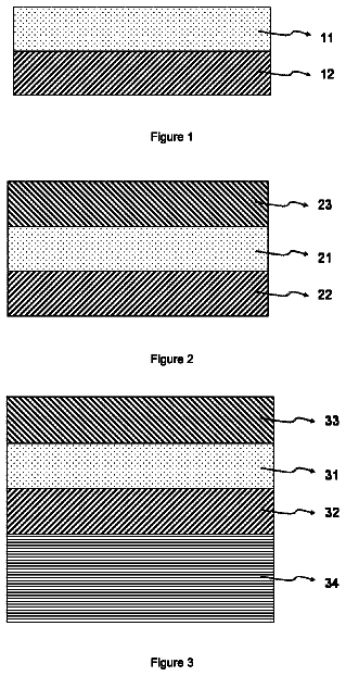
FIG. 1 is a schematic cross-sectional view of an example of an inkjet recording sheet of the present invention.
FIG. 2 is a schematic cross-sectional view of another example of the inkjet recording sheet of the present invention.
FIG. 3 is a schematic cross-sectional view of another example of the inkjet recording sheet of the present invention.
FIG. 4 is a schematic cross-sectional view of an example of a printed article of the present invention.
FIG. 5 is a schematic cross-sectional view of an example of ornamental glass of the present invention.
Hereinafter, the present invention will be specifically described. The following constituents will be described based on typical embodiments of the present invention in some cases, but the present invention is not limited to such embodiments. In the specification of the present application, “to” is used to signify a range that includes numerical values listed before and after “to” as a lower limit and an upper limit respectively.
[Inkjet Recording Sheet]
The inkjet recording sheet of the present invention has a transparent support and an ink receiving layer disposed on one surface side of the transparent support, and the ink receiving layer is a layer formed by curing a composition containing at least a polymerization initiator and a polymerizable compound.
If such a constitution is adopted, when a printed article and ornamental glass are manufactured by forming an image portion on the inkjet recording sheet of the present invention by an inkjet method, both the ink adhesiveness and the scratch resistance of the ink receiving layer including the image portion and the non-image portion become excellent. When a printed article and ornamental glass are manufactured by forming an image portion on the inkjet recording sheet of the present invention by an inkjet method, both the ink adhesiveness and the scratch resistance of the ink receiving layer including the image portion and a non-image portion become better in the ink receiving layer, which is a layer formed by curing a composition containing a polymerization initiator and a polymerizable compound, than in a layer formed by curing a polymer such as a resin binder by using a cross-linking agent or the like.
As illustrated in FIG. 1 , an inkjet recording sheet 10 of the present invention has a transparent support 1 and an ink receiving layer 2 disposed on one surface side of the transparent support 1 . The ink receiving layer 2 may be disposed on at least one surface side of the transparent support 1 or may be disposed on both surfaces of the transparent support 1 . From the viewpoint of disposing an adhesive layer which will be described later, it is preferable that the ink receiving layer 2 is disposed only on one surface thereof.
As illustrated in FIG. 2 , the inkjet recording sheet 10 of the present invention preferably has an adhesive layer 5 on the other surface side of the transparent support 1 opposite to the surface on which the ink receiving layer 2 is disposed. As illustrated in FIG. 3 , the inkjet recording sheet 10 of the present invention preferably has a release film 6 on the adhesive layer 5 .
As illustrated in FIG. 3 , the inkjet recording sheet 10 of the present invention preferably has interlayers 3 A, 3 B, 3 C, 3 D, 3 E, and 3 F constituted with a single layer or two or more layers, at least between the ink receiving layer 2 and the transparent support 1 or between the adhesive layer 5 and the transparent support 1 . FIG. 3 shows an aspect in which three interlayers 3 A, 3 B, and 3 C are disposed in this order from the transparent support 1 between the ink receiving layer 2 and the transparent support 1 and the three interlayers 3 D, 3 E, and 3 F are disposed in this order from the transparent support 1 between the adhesive layer 5 and the transparent support 1 . However, the present invention is not limited to the embodiment, and the number and order of the interlayers are not particularly limited.
Hereinafter, each member will be described.
<Transparent Support>
As the transparent support, a known support can be used. Examples thereof include a plastic film (for example, polyester, polyethylene, polypropylene, polystyrene, a cyclic olefin-based resin, polyvinyl alcohol, polycarbonate, and cellulose ester such as triacetyl cellulose) and the like.
The transparency of the transparent support refers to the properties of having a transmittance of equal to or greater than 80% with respect to light rays having a wavelength in a range of 380 nm to 780 nm
The transparent support is preferably a film containing polyester as a main component, and may contain an additive such as a plasticizer. The polyester is not particularly limited, and for example, polyethylene terephthalate, polyethylene naphthalate, polubutylene terephthalate, or polybutylene naphthalate is used. Among these, from the viewpoint of the cost and the mechanical strength, polyethylene terephthalate is particularly preferable. The main component means a component contained in the transparent support in a proportion of equal to or greater than 50% by mass.
From the viewpoint of improving the mechanical strength of the support, a transparent support having undergone a stretching treatment is preferable, and a biaxially stretched transparent support is particularly preferable. The stretching ratio is not particularly limited, but is preferably within a range of equal to or greater than 1.5-fold and equal to or less than 7-fold. If the stretching ratio is less than 1.5-fold, the mechanical strength is insufficient in some cases. Inversely, if the stretching ratio is greater than 7-fold, the uniformity of the thickness becomes defective in some cases. The stretching ratio is more preferably within a range of equal to or greater than 2-fold and equal to or less than 5-fold. It is particularly preferable that the transparent support is stretched in two directions orthogonal to each other at a stretching ratio within a range of equal to or greater than 2-fold and equal to or less than 5-fold.
The thickness of the transparent support is kept constant within a range of, for example, equal to or greater than 30 μm and equal to or less than 500 μm, and more preferably kept constant within a range of equal to or greater than 50 μm and equal to or less than 300 μm. If the thickness of the support is less than 30 μm, the support becomes bendy, so it is difficult to handle it in some cases. In contrast, if the thickness of the support is greater than 500 μm, it is difficult to reduce the size or weight of a display device, and there are disadvantages in terms of cost.
Furthermore, as the transparent support, it is preferable to use a transparent support in which at least one of two surfaces thereof has undergone a surface treatment such as a corona discharge treatment, a vacuum glow discharge treatment, or a flame treatment. Through the surface treatment, either or both of two surfaces of the support can be hydrophilized, and thus the wettability of various aqueous coating solutions can be improved. In addition, it is possible to introduce a functional group such as a carboxyl group or a hydroxy group into the support. As a result, it is possible to further improve the adhesion between one surface of the support and the ink receiving layer or the interlayer.
<Ink Receiving Layer>
The ink receiving layer is a layer which is disposed on one surface side of the transparent support and is formed by curing a composition containing at least a polymerization initiator and a polymerizable compound. If necessary, the ink receiving layer may contain other components.
(Polymerizable Compound)
The polymerizable compound is not particularly limited, and known polymerizable compounds can be used. The polymerizable compound may be a photosensitive compound or a thermally polymerizable compound. In the present invention, in order to accomplish both the scratch resistance and the ink adhesiveness, it is preferable to use a photosensitive compound. It is more preferable to select a UV curable compound (a monomer from which a UV curable resin is obtained).
The polymerizable compound in the present invention is preferably an addition polymerizable compound having at least one ethylenically unsaturated double bond. The polymerizable compound is more preferably selected from compounds having at least one ethylenically unsaturated bond and preferably having two or more ethylenically unsaturated bonds on a terminal thereof. These compounds are widely known in the technical field to which the present invention belongs, and can be used in the present invention without particular limitation.
These compounds have a chemical form such as a monomer or a prepolymer, that is, a dimer, a trimer, an oligomer, a mixture of these, and a copolymer of these. As the polymerizable compound, those described in paragraphs “0116” to “0126” of JP2011-127096A can be used, and the content of the gazette is incorporated into the present invention.
Examples of the monomer and the copolymer thereof include unsaturated carboxylic acid (for example, acrylic acid, methacrylic acid, itaconic acid, crotonic acid, isocrotonic acid, or maleic acid), esters thereof, and amides thereof. Among these, esters of unsaturated carboxylic acid and an aliphatic polyol compound and amides of unsaturated carboxylic acid and an aliphatic polyamine compound are preferably used. Furthermore, a product of an addition reaction between unsaturated carboxylic acid esters or unsaturated carboxylic acid amides having a nucleophilic substituent such as a hydroxyl group, an amino group, or a mercapto group and monofunctional or polyfunctional isocyanates or epoxies; a product of a dehydrocondensation reaction between the aforementioned unsaturated carboxylic acid esters or unsaturated carboxylic acid amides and monofunctional or polyfunctional carboxylic acid; and the like are preferably used. In addition, a product of an addition reaction between unsaturated carboxylic acid esters or unsaturated carboxylic acid amides having an electrophilic substituent such as an isocyanate group or an epoxy group and monofunctional or polyfunctional alcohols, amines, or thiols; and a product of a substitution reaction between unsaturated carboxylic acid esters or unsaturated carboxylic acid amides having a dissociative substituent such as a halogen group or a tosyloxy group and monofunctional or polyfunctional alcohols, amines, or thiols are also preferable. Moreover, for example, it is possible to use a group of compounds obtained by substituting the aforementioned unsaturated carboxylic acid with unsaturated phosphonic acid, styrene, vinylether, or the like.
Specific examples of the monomer of the ester of the aliphatic polyol compound and the unsaturated carboxylic acid include an acrylic acid ester such as ethylene glycol diacrylate, triethylene glycol diacrylate, 1,3-butanediol diacrylate, tetramethylene glycol diacrylate, propylene glycol diacrylate, neopentyl glycol diacrylate, trimethylol propane triacrylate, trimethylolpropane ethylene oxide-modified (hereinafter, described as “EO-modified”) triacrylate, trimethylolpropane tris(acryloyloxypropyl) ether, trimethylolethane triacrylate, hexane diol diacrylate, 1,4-cyclohexanediol diacrylate, tetraethylene glycol diacrylate, pentaerythritol diacrylate, pentaerythritol triacrylate, pentaerythritol tetraacrylate, dipentaerythritol diacrylate, dipentaerythritol hexaacrylate, sorbitol triacrylate, sorbitol tetraacrylate, sorbitol pentaacrylate, sorbitol hexaacrylate, tris(acryloyloxyethyl) isocyanurate, polyester acrylate oligomer, isocyanuric acid EO-modified triacrylate, or the like.
As esters other than these, for example, aliphatic alcohol-based esters described in JP1976-47334B (JP-S51-47334B) and JP1982-196231A (JP-S57-196231A), esters having an aromatic skeleton described in JP1984-5240A (JP-S59-5240A), JP1984-5241A (JP-S59-5241A), and JP-1990-226149A (JP-H02-226149A), esters containing an amino group described in JP1989-165613A (JP-H01-165613A), and the like are also preferably used. The aforementioned ester monomers can be used as a mixture.
Specific examples of the monomer of amide of an aliphatic polyamine compound and unsaturated carboxylic acid include methylenebis-acrylamide, methylenebis-methacrylamide, 1,6-hexamethylenebis-acrylamide, 1,6-hexamethylenebis-methacrylamide, diethylenetriamine trisacrylamide, xylylenebisacrylamide, xylylenebismethacrylamide, and the like.
Examples of other preferred amide-based monomers include the monomers having a cyclohexylene structure described in JP1979-21726B (JP-S54-21726B).
Furthermore, a urethane-based addition polymerizable compound manufactured by using an addition reaction between isocyanate and a hydroxyl group is also preferable, and specific examples thereof include a vinyl urethane compound containing two or more polymerizable vinyl groups in a single molecule that is obtained by adding a vinyl monomer, which is represented by the following Formula (V) and has a hydroxyl group, to a polyisocyanate compound described in JP1973-41708B (JP-S48-41708B) having two or more isocyanate groups in a single molecule.
In the following Formula (V), each of R.sup.7 and R.sup.8 independently represents a hydrogen atom or a methyl group. H.sub.2C═C(R.sup.7)COOCH.sub.2CH(R.sup.8)OH Formula (V)
In addition, the urethane acrylates described in JP1976-37193A (JP-S51-37193A), JP1990-32293B (JP-H02-32293B), and JP1990-16765B (JP-H02-16765B) or the urethane compounds having an ethylene oxide-based skeleton described in JP1983-49860B (JP-S58-49860B), JP1981-17654B (JP-S56-17654B), JP1987-39417B (JP-S62-39417B), and JP1987-39418B (JP-S62-39418B) are also preferable. Furthermore, if the polymerizable compounds having an amino structure or a sulfide structure in a molecule that are described in JP1988-277653A (JP-S63-277653A), JP1988-260909A (JP-S63-260909A), and JP1989-105238A (JP-H01-105238A) are used, a (photosensitive) composition extremely excellent in photo-sensing speed can be obtained.
The examples also include the polyfunctional acrylate or methacrylate such as polyester acrylates or epoxy acrylates obtained by reacting an epoxy resin with (meth)acrylic acid as described in JP1973-64183A (JP-S48-64183A), JP1974-43191B (JP-S49-43191B), and JP1977-30490B (JP-S52-30490B); specific unsaturated compounds described in JP1971-43946B (JP-S46-43946B), JP1989-40337B (HP-H01-40337B), and JP1989-40336B (JP-H01-40336B); the vinyl phosphonate-based compound described in JP1990-25493A (JP-H02-25493A); and the like. In some cases, the structure containing a perfluoroalkyl group described in JP 1986-22048A (JP-H61-22048A) is preferably used. Furthermore, the photocurable monomer and oligomer described in The Journal of The Adhesion Society of Japan, Vol. 20, No. 7, pp 300-308
can also be used.
The details of how to use these polymerizable compounds, such as the structure thereof, whether they are used singly or concurrently, and the amount thereof added, can be arbitrarily set according to the design of the final performance of the composition containing a polymerization initiator and a polymerizable compound. For example, from the viewpoint described below, the polymerizable compounds are selected.
In view of the sensitivity, it is preferable that the polymerizable compound has a structure containing many unsaturated groups per single molecule. In many cases, it is preferable that the polymerizable compound has two or more functional groups. In order to enhance the strength of the cured film, it is preferable that the polymerizable compound has three or more functional groups.
In view of the compatibility between the polymerizable compound and other components (for example, a polymerization initiator and a light shielding material (a pigment or a dye) such as titanium dioxide) contained in the composition containing a polymerization initiator and a polymerizable compound and in view of the dispersibility, the selection of the polymerizable compound and/or how to use the polymerizable compound is an important factor. For example, if a low-purity compound is used or if two or more kinds of other components are concurrently used, the compatibility can be further improved in some cases. Furthermore, for the purpose of improving the adhesiveness with respect to the hard surface of a substrate or the like, a specific structure can be selected.
In the present invention, the polymerizable compound is preferably the monomer of the ester of an aliphatic polyol compound and unsaturated carboxylic acid, more preferably an acrylic acid ester or a methacrylic acid ester, and particularly preferably an acrylic acid ester.
From the viewpoint of controlling the physical properties such as a modulus of elasticity of the film, it is preferable to concurrently use two or more kinds of polymerizable compounds. Particularly, from the viewpoint of the ink adhesiveness and the scratch resistance, a combination of (meth)acrylate having two or more functional groups and EO-modified (meth)acrylate having two or more functional groups is preferable.
The polymerizable compound may be completely cured at the time of forming the ink receiving layer, and thus the polymerizable group may not remain in the ink receiving layer. Alternatively, by forming the ink receiving layer at a reduced curing ratio, the polymerizable group may remain in the ink receiving layer. However, from the viewpoint of obtaining excellent ink adhesiveness, it is preferable to cause the polymerizable group (ethylenically unsaturated bond) to remain by reducing the curing ratio.
The method for leaving the polymerizable group of the polymerizable compound in the ink receiving layer is not particularly limited, and for example, it is possible to use a method in which the UV exposure amount is reduced so as to cause the ethylenically unsaturated bond to remain. This method will be explained in a method for manufacturing an inkjet recording sheet of the present invention that will be described later.
The content of the polymerizable compound in the ink receiving layer or in the total solid content of the composition containing a polymerization initiator and a polymerizable compound for forming the ink receiving layer is preferably within a range of 50% by mass to 99% by mass, more preferably within a range of 80% by mass to 98% by mass, and even more preferably within a range of 90% by mass to 97% by mass.
It is preferable that the content is within the above range because then the ink adhesiveness becomes excellent.
(Polymerization Initiator)
The composition containing a polymerization initiator and a polymerizable compound also contains a polymerization initiator.
As the polymerization initiator in the present invention, it is possible to use those known as polymerization initiators described below. As the polymerization initiator, those described in paragraphs “0128” to “0177” of JP2011-127096A can be used.
The polymerization initiator is not particularly limited as long as it has an ability to initiate the polymerization of a polymerizable compound and can be appropriately selected from known polymerization initiators. For example, a polymerization initiator which exhibits photosensitivity with respect to light rays of ultraviolet rays to visible rays is preferable. Furthermore, the polymerization initiator may be an activator which generates an active radical through a certain interaction with a photoexcited sensitizer or may be an initiator which initiates cationic polymerization according to the type of the monomer.
Examples of the polymerization initiator include a halogenated hydrocarbon derivative (for example, a halogenated hydrocarbon derivative having a triazine skeleton or an oxadiazole skeleton), an acyl phosphine compound such as acyl phosphine oxide, hexaarylbiimidazole, an oxime compound such as an oxime derivative, organic peroxide, a thio compound, a ketone compound, an aromatic onium salt, ketoxime ether, an aminoalkylphenone compound, an aminoacetophenone compound, a hydroxyacetophenone compound, and the like. Among these, a hydroxyacetophenone compound is preferably used.
Examples of the halogenated hydrocarbon compound having a triazine skeleton include the compound described in Wakabayashi et al., Bull. Chem. Soc. Japan, 42, 2924 (1969), the compound described in UK1388492B, the compound described in JP1978-133428A (JP-H53-133428A), the compound described in DE3337024B, the compound described in F. C. Schaefer et al., J. Org. Chem, 29, 1527 (1964), the compound described in JP1987-58241A (JP-S62-58241A), the compound described in JP1993-281728A (JP-H05-281728A), the compound described in JP1993-34920A (JP-H05-34920A), the compound described in U.S. Pat. No. 4,212,976A, and the like.
Examples of polymerization initiators other than the above compounds include an acridine derivative (for example, 9-phenylacridine or 1,7-bis(9,9′-acridinyl) heptane), N-phenylglycine or the like, a polyhalogen compound (for example, carbon tetrabromide, phenyl tribromomethyl sulfone, or phenyl trichloromethyl ketone), coumarins (for example, 3-(2-benzofuranoyl)-7-diethylamino coumarin, 3-(2-benzofuroyl)-7-(1-pyrrolidinyl) coumarin, 3-benzoyl-7-diethylaminocoumarin, 3-(2-methoxybenzoyl)-7-diethylaminocoumarin, 3-(4-dimethylaminobenzoyl)-7-diethylaminocoumarin, 3,3′-carbonyl bis(5,7-di-n-propoxycoumarin), 3,3′-carbonylbis(7-diethylaminocoumarin), 3-benzoyl-7-methoxycoumarin, 3-(2-furoyl)-7-diethylaminocoumarin, 3-(4-diethylaminocinnamoyl)-7-diethylaminocoumarin, 7-methoxy-3-(3-pyridylcarbonyl) coumarin, 3-benzoyl-5,7-dipropoxy coumarin, 7-benzotriazol-2-lycoumarin, and the coumarin compounds described in JP1993-19475A (JP-H05-19475A), JP1995-271028A (JP-H07-271028A), JP2002-363206A, JP2002-363207A, JP2002-363208A, JP2002-363209A, and the like), acyl phosphine oxides (for example, bis(2,4,6-trimethylbenzoyl)-phenyl phosphine oxide, bis(2,6-dimethoxybenzoyl)-2,4,4-trimethyl-pentylphenyl phosphine oxide, or Lucirin TPO), metharocenes (for example, bis(η5-2,4-cyclopentadiene-1-yl)-bis(2,6-difluoro-3-(1H-pyrrol-1-yl)-phenyl) titanium, or η5-cyclopentadienyl-η6-cumenyl-iron(1+)-hexafluorophosphate(1−)), the compounds described in JP1978-133428A (JP-S53-133428A), JP1982-1819B (JP-S57-1819B), JP1982-6096B (JP-S57-6096B), U.S. Pat. No. 3,615,455A, and the like.
As the polymerization initiator, a hydroxyacetophenone compound, an aminoalkylphenone compound, an aminoacetophenone compound, and an acyl phosphine compound can also be preferably used. More specifically, for example, it is also possible to use the aminoacetophenone-based initiator described in JP1998-291969A (JP-H10-291969A) and the acyl phosphine oxide-based initiator described in JP4225898B.
As the hydroxyacetophenone-based initiator, it is possible to use IRGACURE-184, DAROCURE-1173, IRGACURE-500, IRGACURE-2959, and IRGACURE-127 (trade names, all manufactured by BASF). As the aminoalkylphenone-based initiator, it is possible to use IRGACURE-907, IRGACURE-369, and IRGACURE-379EG (trade names, all manufactured by BASF). As the aminoacetophenone-based initiator, it is possible to use IRGACURE-907, IRGACURE-369, and IRGACURE-379 (trade names, all manufactured by BASF) which are commercially available products. As the aminoacetophenone-based initiator, it is also possible to use the compound described in JP2009-191179A whose absorption wavelength is matched with a light source having a wavelength of 365 nm, 405 nm, or the like. Furthermore, as the acyl phosphine-based initiator, it is possible to use IRGACURE-819 or DAROCURE-TPO (trade names, all manufactured by BASF) which is a commercially available product.
As the polymerization initiator, an oxime-based compound can also be preferably used. Specific examples of the oxime-based initiator include the compounds described in JP2001-233842A, JP2000-80068A, and JP2006-342166A.
Examples of oxime ester compounds include the compounds described in J. C. S. Perkin II (1979), pp. 1653-1660, J. C. S. Perkin II (1979), pp. 156-162, Journal of Photopolymer Science and Technology (1995), pp. 202-232, and JP2000-66385A, the compounds described in JP2000-80068A, JP2004-534797A, and JP2006-342166A, and the like.
As commercially available products, IRGACURE-OXE01 (manufactured by BASF) and IRGACURE-OXE02 (manufactured by BASF) are also preferably used.
As oxime ester compounds other then the compounds described above, the compound described in JP2009-519904A in which oxime is linked to N-position of carbazole, the compound described in U.S. Pat. No. 7,626,957B in which a hetero substituent is introduced into a benzophenone site, the compound described in JP2010-15025A and US2009/292039A in which a nitro group is introduced into a colorant site, the ketoxime-based compound described in WO2009/131189A, the compound described in U.S. Pat. No. 7,556,910B containing a triazine skeleton and an oxime skeleton in the same molecule, the compound described in JP2009-221114A having maximal absorption at 405 nm and exhibiting excellent sensitivity with respect to a light source of g-line, and the like may also be used.
If necessary, the polymerization initiator used in the present invention may be used in combination of two or more kinds thereof
The content of the polymerization initiator contained in the ink receiving layer (total content when the ink receiving layer contains two or more kinds of polymerization initiators) is preferably equal to or greater than 0.1% by mass and equal to or less than 50% by mass, more preferably equal to or greater than 0.5% by mass and equal to or less than 30% by mass, and even more preferably equal to or greater than 0.5% by mass and equal to or less than 20% by mass, with respect to the total solid content thereof. If the content is within the above range, excellent sensitivity is obtained.
In the present invention, from the viewpoint of the appropriate hardness and the adhesiveness, the content of the polymerization initiator contained in the ink receiving layer is particularly preferably equal to or greater than 2% by mass and equal to or less than 10% by mass.
(Others)
If necessary, the ink receiving layer may contain a surfactant, a resin, a cross-linking agent, a slip agent, an anti-foaming agent, a foam inhibitor, a dye, a fluorescent whitening agent, a preservative, an insolubilizer, particles, an organic solvent, distilled water, and the like, in addition to the polymerizable compound and the polymerization initiator.
From the viewpoint of improving the ink adhesiveness, it is preferable that the ink receiving layer contains a surfactant. From the viewpoint of further improving the ink adhesiveness, it is more preferable that the ink receiving layer contain a fluorine-based surfactant although there is no definite theory about what brings about the improvement.
In the present invention, the content of the surfactant contained in the ink receiving layer is preferably 0.01% by mass to 5% by mass, more preferably 0.05% by mass to 2% by mass, and particularly preferably 0.1% by mass to 1% by mass.
Examples of the surfactant include known anionic, nonionic, and cationic surfactants, a known fluorine-based surfactant, and a known silicone-based surfactant. The surfactant is described in, for example, “Surfactant Handbook” (Ichiro Nishi, Ichiro Imai, and Shozo Kasai, Sangyo Tosho Publishing Co., Ltd., 1960).
The fluorine-based surfactant is preferably used because it brings about an effect, particularly, an effect of improving the ink adhesiveness even added in an small amount. Furthermore, the fluorine-based surfactant brings about an effect of improving coating unevenness, drying unevenness, and planar defect such as point defect, and can increase the productivity by improving planar evenness with imparting high-speed coating suitability.
Preferred examples of the fluorine-based surfactant include a fluoroaliphatic group-containing copolymer (simply described as a “fluorine-based polymer” in some cases).
It is preferable that the fluorine-based polymer has a constitutional unit derived from fluorine-containing vinyl monomer and a constitutional unit for imparting cross-linking properties. Preferred examples of the constitutional unit of the fluorine-based polymer include the compounds described in paragraphs “0095” to “0102” of JP2011-75942A.
Preferred examples of the fluorine-based polymer include the compounds described in paragraphs “0049” to “0074” of JP2007-188070A and fluorine-based polymers FP-13, GF-1, GF-2, and GF-3 represented by the following structural formulae described in paragraph “0153” of JP2011-75942A.
a/b=90/10 (% by mass)
In addition, a random copolymer of perfluoroolefin and vinyl ethers or vinyl esters is useful as the fluorine-based polymer. Particularly, it is preferable that the fluorine-based polymer has a group which can cause a cross-linking reaction alone {a radically polymerizable group such as a (meth)acryloyl group or a ring-opening polymerizable group such as an epoxy group or an oxetanyl group}. These polymerization units containing a group having cross-linking reactivity preferably account for 5 mol % to 70 mol % and particularly preferably account for 30 mol % to 60 mol % of the total polymerization units of the polymer. Preferred examples of the polymer include those described in JP2002-243907A, JP2002-372601A, JP2003-26732A, JP2003-222702A, JP2003-294911A, JP2003-329804A, JP2004-4444A, and JP2004-45462A.
The description continues in the full USPTO document.
About 5,865 words. The USPTO PDF has it with every drawing.
Fees are due 3.5, 7.5 and 11.5 years after grant. This patent expired on October 3, 2025, so the fee marked "not paid" was the one that went unpaid.
INKJET RECORDING SHEET, METHOD FOR MANUFACTURING INKJET RECORDING SHEET, PRINTED ARTICLE, METHOD FOR MANUFACTURING PRINTED ARTICLE, AND ORNAMENTAL GLASS
Filed Feb 2016 · published Jun 2016Inkjet recording sheet, method for manufacturing inkjet recording sheet, printed article, method for manufacturing printed article, and ornamental glass
Filed Feb 2016 · granted Oct 2017Earlier publications, parents and continuations. None of them can still be enforced, or this patent would not be listed.
Prior art cited by the examiner or applicant. Useful when you check your own idea for novelty.
Everything on this page comes from the documents linked above.