Background
The present disclosure relates to a hollow elongated member configured for deflection.
A hollow elongated member is used as an access tool for introducing various medical devices into a body cavity or a lumen of a living body or as a member which configures an insertion portion or the like of a flexible endoscope. An elongated member of the type described is configured such that it can deflect following a shape or the like of a biological organ so that a movement thereof in the living body can be carried out smoothly.
Japanese Patent Laid-Open No. Hei 9-117413) discloses an elongated member as a member for use for an insertion portion of a flexible endoscope. The elongated member is configured by connecting a plurality of first tubular elements having a groove formed thereon and a plurality of second tubular elements having a projected engaging portion provided thereon for engaging with the groove. In the elongated member, a push-pull member connected to the elongated member or the like is pulled by a hand to move adjacent ones of the tubular elements relative to each other to deflect the elongated member. Further, an operation for loosening the force applied by the pulling is carried out to deform the elongated member into a linear shape.
In such an elongated member as described above, the force applied to deflect the elongated member is transmitted from the proximal end side to the distal end side through engagement between the groove and the engaging portion of the tubular elements. Therefore, the ease in transmission of force upon operation depends much upon the shape of the groove, engaging portion and and other relevant features of the tubular elements.
Summary of the disclosure
As an example, where a gap is formed in a shape substantially same as an outer shape of the engaging portion, the movement (pivotal movement) of the engaging portion in the groove is restricted as disclosed in Japanese Patent Laid-Open No. Hei 9-117413. Therefore, a rotational moment generated when the engaging portion moves is not transmitted efficiently along a longitudinal direction of the elongated member. Therefore, the deflection motion of the elongated member does not follow the operation of the push-pull member and the deflection motion is not carried out smoothly. Further, since the range of the movement of the engaging portion is limited, the deflection amount is also limited, and deflection of the elongated member following the shape of a biological organ or the like is not readily carried out. Accordingly, where the elongated member described above is used as a component of a medical device or the like, it degrades the operability of the medical device and hence degrades the usability of the medical device.
It is an intention of the present disclosure to provide an elongated member in which a movement of an engaging portion in a grooved portion provided on a deflection mechanism can be transmitted favorably from the proximal end side to the distal end side thereby to allow a deflection motion to be carried out smoothly and which can be deformed suitably following a shape of a biological organ or the like.
In order to attain the intention described above, according to the present disclosure, there is provided an elongated member which is deflectable and hollow. The elongated member including: an operating member configured to deflect the elongated member or deform the elongated member into a linear state; and a deflection mechanism at least including a guide portion having a grooved portion formed thereon, an engaging portion engageable with the grooved portion and a supporting portion configured to support the engaging portion for relative movement on the guide portion; a gap being formed between the guide portion and the engaging portion so as to allow movement of the engaging portion in the grooved portion.
With the elongated member, if predetermined force is applied to the elongated member through the operating member in order to carry out a deflection motion, then the engaging portion moves with respect to the guide portion provided on the deflection mechanism around a fulcrum provided by the supporting portion. Then, the movement is transmitted in the longitudinal direction of the elongated member. Therefore, the deflection motion of the elongated member can be carried out smoothly. Further, since the range within which the engaging portion can move can be expanded by the gap formed between the guide portion and the engaging portion, deformation of the elongated member can be carried out following a shape of a biological organ or the like.
Preferably, the guide portion, at least, has a first guide face formed so as to extend in a direction crossing with an axial line along a longitudinal direction of the elongated member; a second guide face formed in a symmetrical manner with the first guide face with respect to an axis of symmetry provided by the axial line; a third guide face formed at a position opposing to the first guide face, and a fourth guide face formed at a position opposing to the second guide face; the engaging portion at least has first to fourth abutting portions disposed at positions opposing to the first to fourth guide faces, respectively. The engaging portion is held for movement by the gap to a first position at which the first abutting portion abuts with the first guide face and the fourth abutting portion abuts with the fourth guide face and to a second position at which the second abutting portion abuts with the second guide face and the third abutting portion abuts with the third guide face.
With the elongated member, the engaging portion moves to the first position and the second position within the grooved portion provided on the deflection mechanism. Upon such movement, the first and fourth guide faces of the guide portion and the first and fourth abutting portions of the engaging portion abut with each other, respectively, or the second and third guide faces of the guide portion and the second and third abutting portions of the engaging portion abut with each other, respectively, whereupon force is transmitted in the longitudinal direction of the elongated member. Since force can be transmitted efficiently in the longitudinal direction of the elongated member through the abutment between the guide faces and the abutting portions, the deflection motion of the elongated member can be carried out smoothly.
In this instance, the deflection mechanism preferably has a face shape formed such that the first and second guide faces are formed in an inclined relationship along a circumferential direction with respect to the axial line and the first and second abutting portions abut at least at part thereof with the first and second guide faces, respectively.
With the elongated member, since the first and second abutting portions contact in plane with the first and second guide faces of the guide portion provided on the deflection mechanism, force applied to the elongated member can be transmitted in a higher efficiency in the longitudinal direction. Further, since the deflection shape is maintained in the state in which the guide faces and the abutting portions contact with each other in plane, the deflection shape of the elongated member can be maintained suitably. Consequently, occurrence of an inadvertent change in shape of the elongated member upon deflection motion can be prevented with certainty.
The elongated member preferably has a deflection region formed such that a plurality of deflection mechanisms are disposed at different positions from each other in the longitudinal direction of the elongated member in the deflection region; and the deflection region has a first deflection region, and a second deflection region which is formed on the proximal end side of the elongated member with respect to the first deflection region and in which a spacing distance between the deflection mechanisms neighboring with each other in the longitudinal direction is greater than a spacing distance between the deflection mechanisms neighboring with each other in the longitudinal direction in the first deflection region.
With the elongated member, the spacing distance between the deflection mechanisms neighboring with each other in the longitudinal direction in the second deflection region is set greater than the spacing distance between the deflection mechanisms neighboring with each other in the longitudinal direction in the first deflection region. Therefore, the elongated member can carry out a deflection motion with curvatures different from each other at a plurality of different locations thereof in the longitudinal direction. Accordingly, various models of elongated members conforming to product specifications for medical tools and so forth can be provided.
In this case, preferably the deflection region has a different deflection region in which the grooved portions of at least a set of ones of the deflection mechanisms which neighbor with each other in the longitudinal direction of the elongated member are opposed to each other.
With the elongated member, the grooved portions of at least one set of the deflection mechanisms neighboring with each other are disposed in an opposing relationship to each other in the different deflection region formed on the elongated member. Therefore, when the different deflection region is to be deflected, the deflection motion can be started smoothly with lower force.
In this case, at least one set of the deflection mechanisms which neighbor with each other in the longitudinal direction of the elongated member is disposed in such a manner that the deflection mechanisms are positioned at positions different from each other in a circumferential direction of the elongated member.
With the elongated member, since at least one set of the deflection mechanisms which neighbor with each other in the longitudinal direction of the elongated member is disposed in such a manner that they are positioned at positions different from each other in the circumferential direction of the elongated member, it is possible to permit movement of the engaging portions at a plurality of locations in the circumferential direction, and the elongated member can be deflected more readily.
A plurality of guide portions and a plurality of engaging portions are preferably formed at positions different from each other in a circumferential direction of the elongated member; and the grooved portions of the guide portions formed at positions different from each other in the circumferential direction are communicated with each other through a side groove extending in the circumferential direction.
With the elongated member, since the plurality of guide portions and the plurality of engaging portions are formed at the positions different from each other in the circumferential direction of the elongated member and the grooved portions are communicated with each other through the side groove extending in the circumferential direction of the elongated member, the range within which the portions of the elongated member move in the circumferential direction can be expanded. Further, the deflection motion can be carried out smoothly with lower force.
The operating member is preferably configured from a push-pull member configured to be subject to a pushing or pulling operation in the longitudinal direction of the elongated member to deflect the elongated member or deform the elongated member into the linear state.
With the elongated member, it is possible to deflect the elongated member or deform the elongated member into the linear state by a simple operation of pushing or pulling the push-pull member, which configures the operating member, along the longitudinal direction of the elongated member. Therefore, the elongated member is improved in convenience in use.
In this case, the operating member is disposed in a threading groove formed so as to extend in the longitudinal direction of the elongated member.
With the elongated member, since the operating member is disposed in the threading groove formed on the elongated member, the elongated member can be configured with a reduced diameter regardless of the installation of the operating member.
In this case, preferably the elongated member further includes an elastic member configured to cover an outer surface of the operating member disposed in the threading groove and the elongated member.
With the elongated member, since the elastic member which covers the outer surface of the elongated member is provided, circulation of fluid to the inner side and the outer side of the elongated member through the grooved portion can be prevented. Further, it is possible to achieve protection of the elongated member and protection of a living body of an introduction target. In addition, elasticity can be provided to the elongated member such that the elongated member can be configured so as to be elastically deformable and occurrence of coming off of the operating member from the threading groove can be prevented favorably.
The above and other features of the invention, including various novel details of construction and combinations of parts, will now be more particularly described with reference to the accompanying drawings and pointed out in the claims. It will be understood that the particular device embodying the invention is shown by way of illustration only and not as a limitation of the invention. The principles and features of this invention may be employed in various and numerous embodiments without departing from the scope of the invention.
Brief description of the drawings
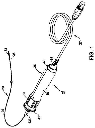
FIG. 1 is a schematic view depicting an elongated member according to an embodiment of the present disclosure in a simplified form;
FIG. 2 is a partial enlarged view depicting a distal end portion of the elongated member as viewed in a direction indicated by an arrow mark 2 in FIG. 1 ;
FIG. 3 is a developed view depicting the elongated member developed in a broken line region 3 in FIG. 1 ;
FIG. 4 is a developed view depicting the elongated member developed in a broken line region 4 in FIG. 1 ;
FIG. 5 is a developed view depicting the elongated member developed in a broken line region 5 in FIG. 1 ;
FIG. 6A is a plan view depicting, in an enlarged scale, a guide portion and an engaging portion provided in a first deflection region and illustrating an action of the elongated member depicted in FIG. 1 ;
FIG. 6B is a plan view depicting, in an enlarged scale, a manner in which the engaging portion provided in the first deflection region moves and illustrating an action of the elongated member depicted in FIG. 1 ;
FIG. 6C is a plan view depicting, in an enlarged scale, another manner in which the engaging portion provided in the first deflection region moves and illustrating an action of the elongated member depicted in FIG. 1 ;
FIG. 7A is a plan view depicting, in an enlarged scale, a guide portion and an engaging portion provided in a second deflection region and illustrating an action of the elongated member depicted in FIG. 1 ;
FIG. 7B is a plan view depicting, in an enlarged scale, a manner in which the engaging portion provided in the second deflection region moves and illustrating an action of the elongated member depicted in FIG. 1 ;
FIG. 7C is a plan view depicting, in an enlarged scale, another manner in which the engaging portion provided in the second deflection region moves and illustrating an action of the elongated member depicted in FIG. 1 ;
FIG. 8A is a plan view depicting, in an enlarged scale, a guide portion and an engaging portion provided in a different deflection region and illustrating an action of the elongated member depicted in FIG. 1 ;
FIG. 8B is a plan view depicting, in an enlarged scale, a manner in which the engaging portion provided in the different deflection region moves and illustrating an action of the elongated member depicted in FIG. 1 ;
FIG. 8C is a plan view depicting, in an enlarged scale, another manner in which the engaging portion provided in the different deflection region moves and illustrating an action of the elongated member depicted in FIG. 1 ;
FIG. 9A is a plan view depicting, in an enlarged scale, a guide portion and an engaging portion of an elongated member according to a modification and illustrating an action of the elongated member;
FIG. 9B is a plan view depicting, in an enlarged scale, a manner in which the engaging portion moves and illustrating an action of the elongated member according to the modification;
FIG. 9C is a plan view depicting, in an enlarged scale, another manner in which the engaging portion moves and illustrating an action of the elongated member according to the modification;
FIG. 10A is a plan view depicting, in an enlarged scale, a guide portion and an engaging portion of an elongated member according to a different modification and illustrating an action of the elongated member;
FIG. 10B is a plan view depicting, in an enlarged scale, a manner in which the engaging portion moves and illustrating an action of the elongated member according to the different modification; and
FIG. 10C is a plan view depicting, in an enlarged scale, another manner in which the engaging portion moves and illustrating an action of the elongated member according to the different modification.
Detailed description of the preferred embodiments
An embodiment of the present disclosure is now described with reference to the drawings. It is to be noted that a dimensional rate in the figures is exaggerated for the convenience of illustration and is sometimes different from an actual ratio.
FIGS. 1 to 5 depict a configuration of components of an elongated member according to one embodiment, and FIGS. 6A to 8C illustrate different actions of the elongated member of the embodiment. It is to be noted that, in the following description, the left side of the elongated member in FIG. 1 is referred to as “distal end side of the elongated member” and the right side is referred to as “proximal end side of the elongated member.” Further, the leftward and rightward direction of the elongated member in FIG. 1 is referred to as “longitudinal direction of the elongated member.”
Referring first to FIG. 1 , an elongated member 10 according to the present embodiment is configured as a deflectable hollow elongated member and has an outer shape elongated in the longitudinal direction. As hereinafter described, if a predetermined operation is performed for the elongated member 10 , then a deflection motion in which at least part of the elongated member 10 is deflected is carried out. The elongated member 10 can be used in various devices, tools, instruments and the like, used in the medical field, and can be used, for example, as a guiding tool for introducing a medical tool, instrument or the like to a predetermined target region in a living body through a body cavity or a lumen (for example, a blood vessel, the bile duct, a respiratory tract, a digestive tract, the urethra and so forth) of the living body, through an insertion portion of a flexible endoscope, or through a member configuring a shaft portion of a balloon catheter or the like.
The components of the elongated member according to the present embodiment are described in detail below.
As depicted in FIGS. 1, 2 and 3 , the elongated member 10 includes an operating member 70 ( FIG. 2 ) for deflecting the elongated member 10 or deforming the elongated member 10 to a linear state, and a deflection mechanism 20 . The deflection mechanism 20 at least includes a guide portion 15 having a grooved portion 30 formed thereon, an engaging portion 40 engageable with the grooved portion 30 , and a supporting portion 18 for supporting the engaging portion 40 for relative movement on the guide portion 15 . A gap g is formed between the guide portion 15 and the engaging portion 40 such that it permits a movement of the engaging portion 40 in the grooved portion 30 .
As depicted in FIGS. 3 and 6A , the guide portion 15 at least has a first guide face 31 , a second guide face 32 , a third guide face 33 and a fourth guide face 34 . The first guide face 31 is formed so as to extend in a direction crossing with an axial line C extending along the longitudinal direction of the elongated member 10 . The second guide face 32 is formed symmetrically with the first guide face 31 with respect to an axis of symmetry provided by the axial line C. The third guide face 33 is formed at a position opposing to the first guide face 31 , and the fourth guide face 34 is formed at a position opposing to the second guide face 32 . Further, the engaging portion 40 includes a first abutting portion 41 , a second abutting portion 42 , a third abutting portion 43 and a fourth abutting portion 44 . The first abutting portion 41 is disposed at a position opposing to the first guide face 31 . The second abutting portion 42 is disposed at a position opposing to the second guide face 32 . The third abutting portion 43 is disposed at a position opposing to the third guide face 33 , and the fourth abutting portion 44 is disposed at a position opposing to the fourth guide portion 34 .
As depicted in FIGS. 6A to 6C , the engaging portion 40 is permitted to move to a first position P 1 (refer to FIG. 6B ) and a second position P 2 (refer to FIG. 6C ) by the gap g. At the first position P 1 , the first abutting portion 41 of the engaging portion 40 abuts with the first guide face 31 of the guide portion 15 and besides the fourth abutting portion 44 of the engaging portion 40 abuts with the fourth guide face 34 of the guide portion 15 . At the second position P 2 , the second abutting portion 42 of the engaging portion 40 abuts with the second guide face 32 of the guide portion 15 and besides the third abutting portion 43 of the engaging portion 40 abuts with the third guide face 33 of the guide portion 15 . For example, if the engaging portion 40 moves toward the first position P 1 as depicted in FIG. 6B , then a deflection motion in which the elongated member 10 is deflected in one direction (to the lower side in FIG. 1 ) is carried out. However, if the engaging portion 40 moves toward the second position P 2 as depicted in FIG. 6C , then a deflection motion in which the elongated member 10 is deflected in the other direction (to the upper side in FIG. 1 ) is carried out.
Further, as depicted in FIGS. 6A to 6C , in the present embodiment, the first guide face 31 and the second guide face 32 of the guide portion 15 of the deflection mechanism 20 are formed in an inclined relationship along a circumferential direction with respect to the axial line C. The first abutting portion 41 and the second abutting portion 42 of the engaging portion 40 are configured so as to have a face shape formed so as to abut at least at part thereof with the first and second guide faces 31 and 32 , respectively. In the following description of the present embodiment, the first to fourth abutting portions are represented as first to fourth engaging faces 41 to 44 .
Referring to FIGS. 1 and 3 , the elongated member 10 can be configured, for example, from a hollow tube material to which various processes are performed. The tube material may be comprised of, for example, a metal material, a hard resin material and so forth can be used. The metal material may include, for example but is not limited to, stainless steel, nickel-titanium alloy or the like can be used. The resin material may include, for example but is not limited to, hard polyethylene such as polypropylene (PP), high-density polyethylene (HDPE), polyethylene terephthalate (PET), or polybutylene terephthalate (PBT), hard urethane, polyimide (PI), polystyrene, polyether ether ketone (PEEK), polyamide, polyether imide, polyamide-imide, modified polyphenyleneether, polycarbonate or the like. Further, for the tube material, for example, a tube material of a cylindrical shape on which a distal end opening 11 , a proximal end opening 13 , and a lumen 14 extending from the distal end opening 11 to the proximal end opening 13 are formed can be used.
The deflection mechanism 20 provided on the elongated member 10 can be formed by forming a slit of a predetermined shape which extends from an outer face to an inner face (or from an inner face to an outer face) on the tube material. A working method for forming the slit can be suitably selected in accordance with a nature of a material to be used and is not limited particularly. However, a known method such as, for example, laser processing or etching can be selectively used.
The guide portion 15 signifies a portion of the elongated member 10 at which the grooved portion 30 is formed. Further, the supporting portion 18 is configured from portions at which the guide portion 15 and the engaging portion 40 contact with and support each other, and in the present embodiment, from a base point 37 of the guide portion 15 and a base point 47 of the engaging portion 40 hereinafter described.
The dimension in the longitudinal direction, inner diameter, outer diameter and so forth, of the elongated member 10 can be designed in accordance with the usage of the elongated member 10 , specifications of a product to which the elongated member 10 is applied and so forth and is not limited particularly. However, for example, the elongated member 10 can be formed so as to have a length of 50 to 1000 mm, an inner diameter of 1 to 5 mm and an outer diameter of 2 to 6 mm.
The elongated member 10 is configured such that it can be deflected over a predetermined range in the longitudinal direction by disposing a plurality of deflection mechanisms 20 at positions different from each other in the longitudinal direction. Further, in order to allow different portions of the elongated member 10 to be deflected with different curvatures from each other, a plurality of deflection regions 100 , 200 and 300 are provided on the elongated member 10 .
The first deflection region 100 is a region formed at the distal end side of the elongated member 10 and is a portion which allows the elongated member 10 to be deflected by a comparatively high curvature. The second deflection region 200 is a region formed on the proximal end side of the elongated member 10 with respect to the first deflection region 100 and is formed, in the present embodiment, over a predetermined range from the proximal end portion of the elongated member 10 . The second deflection region 200 makes it possible for the elongated member 10 to be deflected by a curvature smaller than that of the first deflection region 100 . The different deflection region 300 is formed between the first deflection region 100 and the second deflection region 200 and is a portion which allows the elongated member 10 to be deflected by a curvature smaller than that of the first deflection region 100 but greater than that of the second deflection region 200 .
Since the relationship of the curvatures of the deflection regions 100 , 200 and 300 in the elongated member 10 is set in such a manner as described above, a deflection motion is carried out such that the curvature gradually decreases from the distal end side to the proximal end side. By the deflection regions 100 , 200 and 300 , such predetermined functions as described below are provided to the elongated member 10 . The distal end side of the elongated member 10 has a great deflectable range such that it is deformed following the shape of a biological organ or the like. In this manner, it is easy for the distal end side of the elongated member 10 to reach a target peripheral position in a living body. The second deflection region 200 deflects the elongated member 10 by a comparatively small curvature. Therefore, the second deflection region 200 functions as a shaft portion which suitably transmits push-pull force provided by an operation on the hand side to the distal end side. The different deflection region 300 has a function as a shaft portion and further makes it possible to deflect the elongated member 10 by a predetermined curvature on the backbone side (central side) of the living body on which such a high curvature as is required in a peripheral position in the living body is not required.
The dimensions of the deflection regions 100 , 200 and 300 in the longitudinal direction can be designed suitably in accordance with a usage and so forth of the elongated member 10 and are not limited particularly. However, in the present embodiment, the length of the first deflection region 100 is in the range of approximately 10 to approximately 100 mm; the length of the second deflection region 200 is in the range of approximately 20 to approximately 200 mm; and the length of the different deflection region 300 is in the range of approximately 20 to approximately 700 mm.
In the following description, a deflection mechanism, a grooved portion and an engaging portion formed in the first deflection region 100 are referred to as first deflection mechanism 20 , first grooved portion 30 and first engaging portion 40 , respectively. A deflection mechanism, a grooved portion and an engaging portion formed in the second deflection region 200 are referred to as second deflection mechanism 220 , second grooved portion 230 and second engaging portion 240 , respectively. A deflection mechanism, a grooved portion and an engaging portion formed in the different deflection region 300 are referred to as third deflection mechanism 320 , third grooved portion 330 and third engaging portion 340 , respectively.
Referring to FIGS. 3 and 6A , the first guide face 31 and the second guide face 32 of the first grooved portion 30 formed in the first deflection region 100 are formed in an inclined relationship to the distal end side in the longitudinal direction of the elongated member 10 . The first engaging face 41 and the second engaging face 42 of the first engaging portion 40 are formed in an inclined relationship to the distal end side in the longitudinal direction of the elongated member 10 .
The angle by which the first guide face 31 and the second guide face 32 of the first grooved portion 30 of the guide portion 15 are inclined with respect to the axial line C may be, for example, 5 to 30 degrees in the plan views depicted in FIGS. 3 and 6A . The distal end shape of the first grooved portion 30 formed by connection of the first guide face 31 and the second guide face 32 is a substantially V shape in which the base point 37 at which the first guide face 31 and the second guide face 32 merge is formed on the axial line C.
The third guide face 33 and the fourth guide face 34 of the first grooved portion 30 of the guide portion 15 are formed such that they extend in an inclined relationship with respect to the axial line C. The angle by which the third guide face 33 and the fourth guide face 34 are inclined with respect to the axial line C can be, for example, 5 to 30 degrees as viewed in the plan view of FIG. 6A .
A fifth guide face 35 is formed on the first grooved portion 30 of the guide portion 15 such that it continues to the first guide face 31 and the third guide face 33 . The fifth guide face 35 is formed in an inclined relationship by a predetermined angle from the first guide face 31 side to the third guide face 33 side. Further, a sixth guide face 36 is formed on the first grooved portion 30 such that it continues to the second guide face 32 and the fourth guide face 34 . The sixth guide face 36 is formed in an inclined relationship by a predetermined angle from the second guide face 32 side to the fourth guide face 34 side.
The first engaging portion 40 is formed slightly smaller than the first grooved portion 30 and is disposed so as to be accommodated in the first grooved portion 30 . The angle by which the first engaging face 41 and the second engaging face 42 of the first engaging portion 40 are inclined with respect to the axial line C is set smaller than the angle by which the first guide face 31 and the second guide face 32 of the first grooved portion 30 are inclined with respect to the axial line C and can be, for example, 0 to 25 degrees as viewed in the plan view of FIG. 6A . A distal end shape of the first engaging portion 40 formed by the connection of the first engaging face 41 and the second engaging face 42 is a substantially V shape in which the base point 47 at which the first engaging face 41 and the second engaging face 42 merge is formed on the axial line C.
The third engaging face 43 and the fourth engaging face 44 of the first engaging portion 40 are formed such that they extend in an inclined relationship with respect to the axial line C. The angle by which the third engaging face 43 and the fourth engaging face 44 are inclined with respect to the axial line C is set smaller than the angle by which the third and fourth guide faces 33 and 34 of the first grooved portion 30 are inclined with respect to the axial line C and can be set, for example, to 0 to 25 degrees on the plan view of FIG. 6A .
A fifth engaging face 45 of the first engaging portion 40 is formed in a continuing relationship to the first engaging face 41 and the third engaging face 43 and is inclined by a predetermined angle from the first engaging face 41 side to the third engaging face 43 side.
A sixth engaging face 46 of the first engaging portion 40 is formed in a continuing relationship to the second engaging face 42 and the fourth engaging face 44 and is inclined by a predetermined angle from the second engaging face 42 side to the fourth engaging face 44 side similarly to the fifth engaging face 45 .
As depicted in FIG. 3 , a first extension 48 is formed at the proximal end of the first engaging portion 40 formed in the first deflection region 100 such that it continues to the first deflection mechanism 20 neighboring therewith in the longitudinal direction. Correspondingly, a second extension 49 is formed on the first deflection mechanism 20 such that it extends in a circumferential direction and continues to the first deflection mechanism 20 neighboring therewith in a circumferential direction. The first deflection region 100 is configured such that a plurality of deflection mechanisms 20 are connected to each other by the extensions 48 and 49 .
In the first deflection region 100 , a plurality of first grooved portions 30 and a plurality of first engaging portions 40 are formed at positions different from each other in a circumferential direction (upward and downward direction in FIG. 3 ) of the elongated member 10 . Further, for example, two first grooved portions 30 and two first engaging portions 40 can be disposed at positions same as each other in the longitudinal direction but displaced by 180 degrees in the circumferential direction such that the first grooved portions 30 and the first engaging portions 40 are individually opposed to each other on the circumference.
The first grooved portions 30 formed at the different positions in the circumferential direction are communicated with each other through a side groove 50 extending in the circumferential direction of the elongated member 10 . By forming the plurality of first grooved portions 30 and the plurality of first engaging portions 40 at different positions from each other in the circumferential direction such that the first grooved portions 30 are communicated with each other by the side groove 50 , the range over which the first deflection region 100 can move in the circumferential direction can be expanded, and a deflection motion of the elongated member 10 can be commenced smoothly by lower force.
The shape of the side groove 50 may be, for example, a substantially elliptical shape in which the width of the side groove 50 gradually increases from the side of one of the first grooved portions 30 disposed adjacent in the circumferential direction to the side of the other first grooved portion 30 and gradually decreases from the middle.
With reference to FIGS. 4 and 7A , a first guide face 231 and a second guide face 232 of the second grooved portion 230 formed on the second deflection region 200 are formed in an inclined relationship to the distal end side in the longitudinal direction of the elongated member 10 . Also a first engaging face 241 and a second engaging face 242 of the second engaging portion 240 are formed in an inclined relationship to the distal end side in the longitudinal direction of the elongated member 10 . Also in the second deflection region 200 , a plurality of second grooved portions 230 and a plurality of second engaging portions 240 can be formed in a circumferential direction of the elongated member 10 similarly as in the case of the first deflection region 100 .
As depicted in FIG. 4 , in the second deflection region 200 , the spacing distance d 2 between the second deflection mechanisms 220 neighboring with each other in the longitudinal direction is set greater than the spacing distance d 1 between the first deflection mechanisms 20 positioned adjacent each other in the longitudinal direction in the first deflection region 100 (refer to FIG. 3 ).
By setting the spacing distance d 2 in the second deflection region 200 greater than the spacing distance d 1 in the first deflection region 100 in this manner, the curvature when the second deflection region 200 is deflected can be made smaller than the curvature when the first deflection region 100 is deflected without carrying out such design as to change the shape of the second grooved portion 230 or the shape of the second engaging portion 240 from the shape of the first grooved portion 30 or the shape of the first engaging portion 40 formed in the first deflection region 100 .
The shape of the second grooved portion 230 and the second engaging portion 240 formed in the second deflection region 200 can be configured similarly to those of the first grooved portion 30 and the first engaging portion 40 formed in the first deflection region 100 . However, in the second deflection region 200 , it is omitted to form the first extension 48 continuing to and between the second deflection mechanisms 220 neighboring with each other in the longitudinal direction or the second extension 49 continuing to and between the second deflection mechanisms 220 neighboring with each other along the circumferential direction. Further, as depicted in FIG. 4 , the supporting portion 18 is configured from a base point 237 formed on the guide portion 15 and a base point 247 formed on the second engaging portion 240 .
In the second deflection region 200 , at least one set of second deflection mechanisms 220 neighboring with each other in the longitudinal direction of the elongated member 10 is disposed in such a manner that they are arranged at positions different from each other in the circumferential direction (upward and downward direction in FIG. 4 ). Where the second deflection mechanisms 220 neighboring with each other in the longitudinal direction are disposed at positions displaced from each other in the circumferential direction, and since movement of the second engaging portion 240 is permitted at a plurality of locations in the circumferential direction, the elongated member 10 is configured so as to be more deflectable.
Since the curvature of the second deflection region 200 when it is deflected is smaller than the curvature of the first deflection region 100 , the number of second grooved portions 230 to be provided is relatively smaller than the number of first grooved portions 30 of the first deflection region 100 to be provided. Therefore, the second deflection region 200 is formed such that it has a comparatively high rigidity. However, where a plurality of second deflection mechanisms 220 are provided at positions displaced from each other in the circumferential direction as described above, the rigidity can be prevented from being set to an excessively high level.
The description continues in the full USPTO document.
 Lapsed, fee not paid4 drawings