This disclosure incorporates by reference the conference paper LOW COMPLEXITY RATE-DISTORTION OPTIMAL MACROBLOCK MODE SELECTION FOR MPEG-LIKE VIDEO CODERS, by H. Kim and Y. Altunbasak and in Proc. Of IEEE Int. Conf. Multimedia and Expo, Baltimore, Md., July 2003.
This disclosure incorporates by reference the conference paper LOW COMPLEXITY RATE-DISTORTION OPTIMAL MACROBLOCK MODE SELECTION AND MOTION ESTIMATION FOR MPEG-LIKE ENCODERS, BY H. Kim, N. Kamaci, and Y. Altunbasak, submitted to IEEE Transactions on Circuits and Systems for Video Technology, Dec. 2, 2002.
Background of the invention
Field of the Invention
The present invention relates to the enhancement to the processes of compression and transport of multi-media data. Multi-media communications include the transmission, reception and presentation of multi-media data streams, including audio, audio and graphics, video, and synchronized audio and video data.
Multi-media data takes many forms known in the art. For example, audio data are stored as files of binary data using various formats. In some formats, the data are compressed so that the number of binary digits (bits) when stored in the file is less than the number of bits used during presentation to a human observer. Example image formats, often indicated by extensions on the names of the files used to store their data, include GIF, JPEG, TIFF, bit map (BMP), CGM, DXF, EPS, PCX, PDF, PIC, among others. Example audio formats, often indicated by extensions on the names of the files used to store their data, include waveform audio (WAV), MP3, audio interchange file format (AIFF), unix audio (AU), musical instrument digital interface (MIDI), and sound files (SND) among others. Example video formats, often indicated by extensions on the names of the files used to store their data, include QuickTime, AVI and the Motion Picture Experts Group format (MPEG), among others. Further treatment of the subject is provided in the book Video Communication .
Image and Video Compression Standards , V. Bhaskaran and K. Konstantinides, Kluwer Academic, 1995, the contents of which are hereby incorporated in their entirety.
Discussion of the Related Art
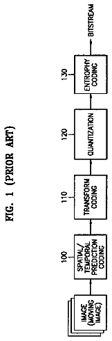
FIG. 1 is a block diagram that illustrates a system for delivering multi-media data using computer hardware over a network. An overview of computer hardware is described in more detail in a later section. On a network, a process called a client process (hereinafter, simply “client”) operating on one computer, called a client device, makes a request of another process called a server process (hereinafter “server”) executing on a computer, called a server device, connected to the network. The server performs the service, often sending information back to the client.
A server device 140 contains multi-media data in a file and a media transmission process 142 that transmits the file over wide area network 155 to the media server device 130 . The media server device 130 includes a media server process 132 that conditions the data for transmission over local network 150 to a media presentation process 112 on media client device 110 . The media presentation process 112 presents the multi-media data to a human user.
The media server device 130 , the local network 150 and the media client device 110 constitute an access link that is sometimes called the “last mile,” and sometimes called the “first mile,” of the multi-media communications.
In some embodiments network 150 or network 155 or both are networks that use the Internet Protocol (IP) described below. In other embodiments, network 150 or network 155 or both are non-IP networks, such as a network of cable television links. On a cable television link, the media server device 130 is at the cable headend and the media client device 110 is a television set-top box.
The local network 150 may comprise a direct connection between media server device 130 and media client device 110 . In other embodiments, the local network 150 includes one or more transcoders that convert from one type of signal to another, or multiplexers that overlay several data streams on the same line during the same time interval, or both. In some embodiments, the local network 150 includes one or more wireless links.
MPEG is a video compression standard that specifics the operation of the video decoder and the syntax of the compressed bitstream. The video information within the MPEG file represents a sequence of video frames. The amount of information used in MPEG to represent a frame of video varies greatly from frame to frame, based both on the visual content and the technique used to digitally represent (“encode”) that content.
The visual content depends on the intensity (luminance) of each pixel, color space, the spatial variability of each frame, the temporal variability between successive frames, and the ability of the human visual system to perceive the intensity, color and variability.
An MPEG encoder employs three general techniques for encoding frames of video. The three techniques produce three types of frame data: Intra-frame (“I-frame”) data, forward Predicted frame (“P-frame”) data, and Bi-directional predicted frame (“B-frame”) data. I-frame data includes all of the information required to completely recreate a frame. P-frame data contains information that represents the difference between a frame and the frame that corresponds to the previous I-frame or P-frame data. B-frame data contains information that represents relative movement between preceding I-frame data or P-frame data and succeeding I-frame data or P-frame data. These digital frame formats are described for MPEG 2 in detail in the international standard: ISO/IEC138181, 2, 3. Other standards exist for MPEG 1 as well as later MPEG versions. Documents that describe these standards (the “MPEG specifications”) are available from ISSO/IEC copyright Office Case Postale 56, CH 1211, Geneve 20, Switzerland.
The basic idea behind MPEG is to reduce the number of bits required to represent video (video compression) by removing spatial redundancy within a video frame and removing temporal redundancy between video frames. Each frame is made up of two interlaced fields that are alternate groups of rows of pixels. Each field is made up of multiple macroblocks (MBs). Each MB is a two dimensional array of pixels, typically 16 rows of 16 pixels. Each macroblock consists of four luminance blocks, typically 8 rows of 8 pixels each, and two chrominance blocks, also 8 rows of 8 pixels each. Spatial redundancy is reduced using the Discrete Cosine Transform (DCT), typically on a block basis. Motion compensation is used to reduce temporal redundancy, typically on a macroblock basis. During motion compensation, a motion vector is computed that indicates pixel locations on a reference frame that are the basis for a particular macroblock on a different, current frame. Differences between the reference macroblock and the particular macroblock are then subjected to DCT processing.
Each video sequence is composed of a series of groups of pictures (GoPs). Each GoP is composed of a series of frames, beginning with an I-frame. A slice is a series of macroblocks and may make up a field or a portion of a field.
For playback, the data in the MPEG file is sent in a data stream (an “MPEG data stream” or “MPEG bitstream”) to a client. For example, the MPEG bitstream is sent over network 150 from device 130 to device 110 . The MPEG bitstream must conform to certain criteria set forth in the MPEG standards. For example, the MPEG bitstream should provide 30 frames per second but not provide so many bits per second that a client's buffers overflow. One bitstream criterion is that the bit rate be constant, e.g., a particular number of bits are sent each second to represent the 30 frames per second.
Another bitstream criterion is that the bit rate be variable, e.g., a different number of bits may be sent each second as long as a maximum bit rate is not exceeded.
During playback, an MPEG decoder at the client recovers video information from the MPEG bitstream. The video information for each frame is then sent to a display device. The video information is sometimes converted to a form used by a particular display device. For example, for display on televisions employed in the United States, the video information is converted to the National Television System Committee (NTSC) format.
FIG. 2 is a block diagram that illustrates an enhanced MPEG encoder. The blocks represent operations performed on data. These operations may be implemented in hardware or software or some combination of both. Some blocks are conventional and others represent, or include, enhancements that are described in more detail in the following subsections. Each block is labeled for easy reference with a callout numeral either inside or adjacent to the block. Arrows that emerge or impinge on the blocks indicate data flow between operations. The thick arrows, such as the arrow labeled “Video In” that impinges on the preprocessing block 202 , indicate the paths followed by the bulk of the video data. The data arriving on the “Video In” arrow is digital video data.
The preprocessor 202 performs any preprocessing known in the art. For example, the video data is filtered in space and time to remove noise. In another example, the data are converted from different formats, for example from bytes representing values of red, green, blue (RGB data) to values representing luminance and chrominance.
The Frame Delay 204 is used to allow different frames, such as a current frame and a reference frame, to be available simultaneously for comparison in other blocks, such as for motion compensation computations. At subtractor 206 , the video data is differenced from a reference frame, if any.
Switch (SW) 208 passes blocks of video data. The Intra/Inter type of macroblocks is determined by the RD model selector 284 based on information received from other operations, as described in more detail in following subsections. The formatter 210 formats the blocks differently based on whether the block is an Intra block (I-block that stands alone like a block from an I-frame) or an Inter block (block that depends on another block and a motion vector, like at least some blocks from a B-frame or P-frame).
The DCT operation 220 transforms the data in a block from the spatial domain to a wavelength domain using the discrete cosine transform (DCT), providing amplitudes for 64 different two-dimensional wavelengths. The Forward Quantizer 222 reduces the accuracy of representation for the amplitudes, a simple example of this operation is to drop the least significant bits. This is a lossy step of the MPEG encoder; that is, this step discards some information. The information discarded is considered less relevant to a human observer than the information retained. According to some embodiments, the degree of quantization is variable and determined by the Quantization Adapter 224 .
The video data output by the forward quantizer 222 is input to the variable length coder (VLC) encoder and multiplexer (MUX) 230 . VLC is a lossless compression technique that represents the more frequently occurring bit sequences with short codes (using fewer bits) and less frequent bit sequences with longer codes (using more bits). The table associating frequently occurring bit sequences with codes are deduced in the VLC statistics processor 234 .
The output from the VLC encoder and multiplexer 230 is accumulated as a bitstream in buffer 238 . The bit stream is passed to a user, for example over a network, as the output bitstream, labeled “Bits Out” in FIG. 2 .
According to some embodiments, special information is sent to a decoder about future GoPs. This special information is collected in Inter-GoP pre-send buffer 236 and passed to buffer 238 between GoPs.
Results of operations performed in blocks 270 , 280 , 282 , 284 are passed as control signals that affect various operations on the video data flow from pre-processor 202 to buffer 238 , as well as other portions of the MPEG encoder.
The human visual system (HVS) model 270 determines parameters that describe the human response to visual information in the frames output by the frame delay 204 . The HVS parameters help determine the adaptive allocation of bits among different GoPs, different frames within a GoP and different macroblocks within a frame.
The selection of the encoding mode for a particular MB is based on balancing the achievable bit rate and size of the resulting difference (also called distortion) between the actual block and the prediction block, according to embodiments in the RD mode selection operation 284 .
Motion compensated predicted frames and macroblocks are determined, described to a user, and made available for subtracting from reference frames and macroblocks in the motion compensation operations 260 , including operations 262 , 263 , 265 . These operations include the primarily conventional picture store 262 , frame/field/dualprime motion estimator 263 , and the frame/field/dualprime motion compensated predictor 265 . Dualprime refers to a particular mode for motion compensation that is well known in the art but rarely used in current practice.
Input for the motion compensation operations 260 come from the previous MPEG compressed frame, based on the quantized DCT amplitudes. Wavelength domain video data are prepared for motion compensation operations 260 in operations 226 , 228 , 250 , 252 , 254 , and 256 .
In the inverse quantizer 226 , the quantized amplitudes are expanded to their full number of bits, typically with trailing zeroes. In the inverse OCT (IDCT) operation 228 , the wavelength domain amplitudes are converted to spatial information. The spatial information is formatted as blocks within macroblocks in the frame/field unformatter 250 . In the adder 252 , the reconstituted frame is treated as a difference and added to a motion compensated output.
Switch (SW) 254 passes blocks of video data from the motion compensated macroblocks to the adder. Switch (SW) 256 passes blocks of video data with the differences, if any, back in, from the adder 252 to the motion compensation operations 260 .
FIG. 3 is a block diagram that illustrates a computer system 300 upon which an embodiment of the invention may be implemented. Computer system 300 includes a communication mechanism such as a bus 310 for passing information between other internal and external components of the computer system 300 . Information is represented as physical signals of a measurable phenomenon, typically electric voltages, but including, in other embodiments, such phenomena as magnetic, electromagnetic, pressure, chemical, molecular and atomic interactions. For example, north and south magnetic fields, or a zero and non-zero electric voltage, represent two states (0, 1) of a binary digit (bit). A sequence of binary digits constitute digital data that is used to represent a number or code for a character. A bus 310 includes many parallel conductors of information so that information is transferred quickly among devices coupled to the bus 310 . One or more processors 302 for processing information are coupled with the bus 310 . A processor 302 performs a set of operations on information. The set of operations include bringing information in from the bus 310 and placing information on the bus 310 . The set of operations also typically include comparing two or more units of information, shifting positions of units of information, and combining two or more units of information, such as by addition or multiplication. A sequence of operations to be executed by the processor 302 constitute computer instructions.
Computer system 300 also includes a memory 304 coupled to bus 310 . The memory 304 , such as a random access memory (RAM) or other dynamic storage device, stores information including computer instructions. Dynamic memory allows information stored therein to be changed by the computer system 300 . RAM allows a unit of information stored at a location called a memory address to be stored and retrieved independently of information at neighboring addresses. The memory 304 is also used by the processor 302 to store temporary values during execution of computer instructions. The computer system 300 also includes a read only memory (ROM) 306 or other static storage device coupled to the bus 310 for storing static information, including instructions, that is not changed by the computer system 300 . Also coupled to bus 310 is a non-volatile (persistent) storage device 308 , such as a magnetic disk or optical disk, for storing information, including instructions, that persists even when the computer system 300 is turned off or otherwise loses power.
Information, including instructions, is provided to the bus 310 for use by the processor from an external input device 312 , such as a keyboard containing alphanumeric keys operated by a human user, or a sensor. A sensor detects conditions in its vicinity and transforms those detections into signals compatible with the signals used to represent information in computer system 300 . Other external devices coupled to bus 310 , used primarily for interacting with humans, include a display device 314 , such as a cathode ray tube (CRT) or a liquid crystal display (LCD), for presenting images, and a pointing device 316 , such as a mouse or a trackball or cursor direction keys, for controlling a position of a small cursor image presented on the display 314 and issuing commands associated with graphical elements presented on the display 314 .
In the illustrated embodiment, special purpose hardware, such as an application specific integrated circuit (IC) 320 , is coupled to bus 310 . The special purpose hardware is configured to perform operations not performed by processor 302 quickly enough for special purposes. Examples of application specific ICs include graphics accelerator cards for generating images for display 314 , cryptographic boards for encrypting and decrypting messages sent over a network, speech recognition, and interfaces to special external devices, such as robotic arms and medical scanning equipment that repeatedly perform some complex sequence of operations that are more efficiently implemented in hardware.
Computer system 300 also includes one or more instances of a communications interface 370 coupled to bus 310 . Communication interface 370 provides a two-way communication coupling to a variety of external devices that operate with their own processors, such as printers, scanners and external disks. In general the coupling is with a network link 378 that is connected to a local network 380 to which a variety of external devices with their own processors are connected. For example, communication interface 370 may be a parallel port or a serial port or a universal serial bus (USB) port on a personal computer. In some embodiments, communications interface 370 is an integrated services digital network (ISDN) card or a digital subscriber line (DSL) card or a telephone modern that provides an information communication connection to a corresponding type of telephone line. In some embodiments, a communication interface 370 is a cable modem that converts signals on bus 310 into signals for a communication connection over a coaxial cable or into optical signals for a communication connection over a fiber optic cable. As another example, communications interface 370 may be a local area network (LAN) card to provide a data communication connection to a compatible LAN, such as Ethernet. Wireless links may also be implemented. For wireless links, the communications interface 370 sends and receives electrical, acoustic or electromagnetic; signals, including infrared and optical signals, that carry information streams, such as digital data. Such signals are examples of carrier waves.
The term computer-readable medium is used herein to refer to any medium that participates in providing instructions to processor 302 for execution. Such a medium may take many forms, including, but not limited to, non-volatile media, volatile media and transmission media. Non-volatile media include, for example, optical or magnetic disks, such as storage device 308 . Volatile media include, for example, dynamic memory 304 . Transmission media include, for example, coaxial cables, copper wire, fiber optic cables, and waves that travel through space without wires or cables, such as acoustic waves and electromagnetic waves, including radio, optical and infrared waves. Signals that are transmitted over transmission media are herein called carrier waves.
Common forms of computer-readable media include, for example, a floppy disk, a flexible disk, a hard disk, a magnetic tape, or any other magnetic medium, a compact disk ROM (CD-ROM), or any other optical medium, punch cards, paper tape, or any other physical medium with patterns of holes, a RAM, a programmable ROM (PROM), an erasable PROM (EPROM), a FLASH-EPROM, or any other memory chip or cartridge, a carrier wave, or any other medium from which a computer can read.
Network link 378 typically provides information communication through one or more networks to other devices that use or process the information. For example, network link 378 may provide a connection through local network 380 to a host computer 382 or to equipment 384 operated by an Internet Service Provider (ISP). ISP equipment 384 in turn provides data communication services through the public, world-wide packetswitching communication network of networks now commonly referred to as the Internet 390 . A computer called a server 392 connected to the Internet provides a service in response to information received over the Internet. For example, server 392 provides information representing video data for presentation at display 314 .
The invention is related to the use of computer system 300 for implementing the techniques described herein. According to one embodiment of the invention, those techniques are performed by computer system 300 in response to processor 302 executing one or more sequences of one or more instructions contained in memory 304 . Such instructions, also called software and program code, may be read into memory 304 from another computer-readable medium such as storage device 308 . Execution of the sequences of instructions contained in memory 304 causes processor 302 to perform the method steps described herein. In alternative embodiments, hardware, such as application specifics integrated circuit 320 , may be used in place of or in combination with software to implement the invention. Thus, embodiments of the invention are not limited to any specific combination of hardware and software.
The signals transmitted over network link 378 and other networks through communications interface 370 , which carry information to and from computer system 300 , are exemplary forms of carrier waves. Computer system 300 can send and receive information, including program code, through the networks 380 , 390 among others, through network link 378 and communications interface 370 . In an example using the Internet 390 , a server 392 transmits program code for a particular application, requested by a message sent from computer 300 , through Internet 390 , ISP equipment 384 , local network 380 and communications interface 370 . The received code may be executed by processor 302 as it is received, or may be stored in storage device 308 or other nonvolatile storage for later execution, or both. In this manner, computer system 300 may obtain application program code in the form of a carrier wave.
Various forms of computer readable media may be involved in carrying one or more sequence of instructions or data or both to processor 302 for execution. For example, instructions and data may initially be carried on a magnetic disk of a remote computer such as host 382 . The remote computer loads the instructions and data into its dynamic memory and sends the instructions and data over a telephone line using a modem. A modem local to the computer system 300 receives the instructions and data on a telephone line and uses an infra-red transmitter to convert the instructions and data to an infra-red signal, a carrier wave serving as the network link 378 . An infrared detector serving as communications interface 370 receives the instructions and data carried in the infrared signal and places information representing the instructions and data onto bus 310 . Bus 310 carries the information to memory 304 from which processor 302 retrieves and executes the instructions using some of the data sent with the instructions. The instructions and data received in memory 304 may optionally be stored on storage device 308 , either before or after execution by the processor 302 .
The following acronyms and symbols are used in this disclosure: A—represents a first mode for predicting a macroblock, or a macroblock associated with a motion vector. alpha (α)—a coefficient relating distortion to variance and the fraction of zeroed DCT amplitudes, or a constant relating a number of bits to a complexity measure ASIC—application specific integrated circuit; a fast, special purpose processor B—Bi-directional type, represents a second mode for predicting a macroblock B-block—Bi-directional predicted block, based on a reference block in a preceding or subsequent frame and a motion vector B-frame—a frame with at least one B-block b/w—bandwidth CBR—constant bit rate Cideal—ideal congestion window, defined as the product of the data rate for a flow and a delay time D—distortion, a measure of the difference in the visual content between a macroblock and a motion compensated reference macroblock DCT—Discrete Cosine Transform delta (Δ)—a factor for increasing the difference in bits assigned to pixels with more visually sensitive content Dt—threshold of DCT amplitude below which DCT wavelength is zeroed FD—frame difference between pixels in one frame and pixels from a reference frame GoP—group of pictures H—number of header bits H.26x—a family of video compression techniques including H.263 and H.264 HVS—Human visual system I-block—intra-block, a block coded without reference to another block IDCT—inverse DCT I-frame—a frame made entirely of I-blocks IP—Internet protocol for sending data packets over heterogeneous computer networks JND—just noticeable distortion K—coefficient of inverse proportionality between a number of bits to represent DCT amplitudes and the distortion remaining after applying the DCT, or the constant as defined above divided by the variance of the piece of video data represented by the DCT amplitudes. k—an index representing one macroblock of a set of macroblocks in a frame, or a wait time associated with a particular packet priority lambda (λ)—a parameter indicating the relative importance of minimizing a motion vector to minimizing a difference between a current macroblock and a reference macroblock, or a factor used to give more bits to more visually sensitive groups of pixels MB—macroblock, a set of blocks processed together for motion compensation Mbps—Megabits per second MCFD—motion compensated frame difference MCframes—motion compensated frames ME—Motion Estimation MPEG—Motion Picture Experts Group, a family of video compression techniques including MPEG-1, MPEG-2, MPEG-4. MSE—the measure of complexity (e.g., the distortion or the variance) of a GoP Mt—threshold of motion tracked by human observer in HVS model mu (μ)—a factor used to give more bits to more visually sensitive groups of pixels MV—motion vector, used to relate a macroblock in one frame to a pixels in a reference frame Mx—x component of motion vector of a macroblock My—y component of motion vector of a macroblock N—a number of frames of a type indicated by a subscript, or refers to a number of groups of pictures NTSC—National Television System Committee omega (ω)—the ratio of alpha to theta (a/θ), a coefficient relating distortion to variance and number of bits O.5—sub-band coding compression p.sub.i—a probability of occurrence for a group of pixels of a certain class, indicated by subscript i, of multiple classes of visual sensitivity, or a priority for the ith packet in a packet stream PP—priority profile, indicates a list of priorities for packets in a packet stream P-block—Predicted block, based on a reference block in a preceding frame and a motion vector P-frame—a frame with at least one P-block and no B-blocks pixel—picture element, the smallest positional unit for video information Q—degree of quantization, the number of bits for DCT amplitudes, or the number of patterns of sub-macroblocks in a macroblock R—number of bits to represent a piece of video information at a particular stage of processing, also called a rate, or the bit rate for a data flow carrying multimedia data over a network RGB—red, green, blue, a technique for representing video pixels rho (ρ)—the fraction of DCT amplitudes set to zero RISC—reduced instruction set circuit; a relative small, general purpose processor SAD—sum of absolute differences, a measure of the difference between two sets with the same number of pixels SNR—signal to noise ratio SW—block switch, an component of an MPEG encoder/decoder TCP—Transmission Control Protocol, a transport level protocol for IP that detects errors and missing packets theta (θ)—a coefficient relating number of bits to the fraction of zeroed DCT amplitudes T—the number of bits to represent a header and DCT amplitudes associated with a given distortion level according to a bit production model TMN—Test model near-term; a document that specifics a prototype encoder; includes TMN5 used for MPEG2 and TMN10 used for H.263 TV—television VLC—variable length coder, a lossless bit compression technique SUMMARY OF THE INVENTION
Accordingly, the present invention is directed to the efficient compression and transport of video over a network that obviates one or more of the problems due to limitations and disadvantages of the related art. The efficiency in compression results in communication efficiencies in bandwidth-limited media and storage efficiencies in memory-limited media.
An advantage of the present invention is to provide a multi-scale adaptive video coding system, wherein the video data is analyzed at different scales (a multi-frame scale and a single-frame scale) for adaptive bit allocation. The quality of the coded data based on the adaptive bit allocation is evaluated by a Quality Monitor (VQM) block 290 that feeds back the evaluation back to the analysis modules enabling a content-adaptive operation of the encoder.
Another advantage of the present invention is to provide a method of look-ahead processing that determines the complexity of one or more of the GoPs and the frames contained in the GoPs. This is achieved by computing the mean removed sum of absolute (MRSA) values of all the pixels in the intra MB. For an non-intra block, this is computed by finding the minimum of the sum of absolute difference of the non-intra block and the best prediction block, and the MRSA of the non-intra block.
Another advantage of the present invention is to provide for the exploitation of human perception of spatio-temporal activity in a video, known as Human Visual System (HVS), for zero-sum bit allocation for video compression. According to this aspect of the invention, a method for allocating bits among portions of a frame to attain a target bit rate per frame includes performing the steps of: determining a particular class of visual sensitivity for a portion of the frame among a plurality of visual sensitivity classes; determining a number of bits associated with the particular class; and allocating a number of bits for the portion based on the number of bits associated with the particular class, wherein a sum over the plurality of classes of a product of the number of bits associated with each class and the probability that the portion belongs to the class is substantively equal to the target bit rate.
Another advantage of the present invention is to provide a Two-Pass Rate Control approach to adaptively allocate bits for video compression. According to this aspect, a method for allocating bits to a frame includes the steps of determining a first number of bits for a frame to achieve a target bit rate according to a first procedure that produces values for a number of header bits, a number of run-level pairs and a number of DCT bits; and, based on an actual number of run-level pairs for the frame to match the number of DCT bits, determining a second number of bits for the frame; and, allocating the second number of bits to the frame. The determination of the first number of bits is referred to as a first pass, and the determination of the second number of bits is referred to as a second pass.
Another advantage of the present invention is to provide a method for adaptive bit allocation for video compression that involves controlling the bit rate within a GoP. According to this approach, Intra-GoP Rate Control, a method for allocating a number of bits for a group of pictures to a plurality of frames for the group includes the steps of: determining a relationship between a variance in a frame to a number of bits for the frame for each type of frame among an I-frame type, P-frame-type and B-frame type in the group of pictures; determining a variance corresponding to each type of frame in the group of pictures; and determining a number of bits for each type of frame based at least in part on the relationship and the variance of each type of frame and the number of frames of each type of frame.
Another advantage of the present invention is to provide for the selection of quantizer values based on motion compensation. According to this aspect of the invention, a method for determining a degree of quantization for the DCT coefficients in a macroblock of pixels includes the steps of: determining a number of times the said macroblock is used as a reference for a macroblock in a subsequent frame; and determining a degree of quantization based on the number of times the said macroblock is used as a reference.
Another advantage of the present invention is to provide adaptive quantization selection for all the macroblocks in a frame based on the global statistics of the macroblocks in a frame for an optimal balance between bit rate and distortion.
Another advantage of the present invention is to provide for the exploitation of human perception of motion to enable adaptive quantization via a Temporal HVS Model. According to this aspect, a method for reducing the number of bits for certain macroblocks includes performing the steps of: determining whether a macroblock is associated with motion faster than a threshold speed for tracking by a human observer; and, if it is determined that the macroblock is associated motion faster than the threshold speed, using fewer bits to represent DCT amplitudes for blocks in the macroblock.
Another advantage of the present invention is to provide a technique for exploiting human perception involves accurate HVS biased bit rate control within a frame using a modulation function for the quantizer values.
Another advantage of the present invention is to provide enhanced efficiency of the compression and transport of video by improving the process of motion estimation. According a particular embodiment of the invention, a method for determining a macroblock used for motion compensation includes the steps of determining motion content of a frame; and defining at least one of a position of the macroblock and a size of the macroblock based on the motion content.
Another advantage of the present invention is to provide Adaptive Hierarchical Motion Estimation for Video Coding. According to this aspect of the invention, the motion estimation is adapted to the amount of motion present in a video sequence, the number of available compute cycles, source contents, source statistics, coding parameters, etc.
Another advantage of the present invention is to provide the use of ρ-Rate Optimization for Motion Vector selection. According to this aspect of the invention, selecting a motion vector for a particular macroblock relative to a reference frame includes the steps of:
determining a relationship for multiple blocks that relates a distortion between a motion-compensated reference macroblock and the particular macroblock to a number of bits for specifying DCT amplitudes for a difference between the motion compensated macroblock and the particular macroblock;
determining a plurality of rates corresponding to a plurality of candidate reference macroblocks in the reference frame based at least in part on the relationship and the variance of residuals between each candidate reference macroblock and the particular macroblock;
selecting a particular candidate reference macroblock associated with a minimum rate of the plurality of rates; and
determining the motion vector between the particular macroblock and the particular candidate reference macroblock.
Another advantage of the present invention is to provide enhanced efficiency of compression through improvements in mode selection for coding macroblocks. According to this aspect of the invention the coding mode of the macroblock is selected to optimize a rate-distortion criterion and also extended to optimal mode selection for a group of macroblocks.
Additional features and advantages of the invention will be set forth in the description which follows, and in part will be apparent from the description, or may be learned by practice on the invention. The objectives and other advantages, of the invention will be realized and attained by the structure particularly pointed out in the written description and claims hereof as well as the appended drawings.
It is to be understood that both the foregoing general description and the following detailed description are exemplary and explanatory and are intended to provide further explanation of the invention as claimed BRIEF DESCRIPTION OF THE DRAWINGS
The accompanying drawings, which are included to provide a further understanding of the invention and are incorporated in and constitute a part of this specification, illustrate embodiments of the invention and together with the description serve to explain the principles of the invention.
In the drawings:
FIG. 1 is a block diagram that illustrates a system for delivering multi-media data using computer hardware over a network;
FIG. 2 is a block diagram that illustrates an enhanced MPEG encoder;
FIG. 3 is a block diagram that illustrates a computer system upon which an embodiment of the invention may be implemented;
FIG. 4 shows a GoP, which is made up of frames;
FIG. 5 shows a flowchart for the process of quantizer selection based on motion compensation;
FIG. 6 depicts an example of the tracking of macroblocks, as implemented by the Temporal HVS Model aspect of the invention;
FIG. 7 shows an example set of mapping functions for a 3 class MPEG2 system, used in Accurate HVS Biased Bit Rate Control;
FIG. 8 , shows a N×N macroblocks, as used in Image Tiling for Motion Compensation;
FIG. 9 shows the N×N macroblock being partitioned into a predetermined number of patters, according to the Constrained Tiling implementation of Image Tiling for Motion Compensation;
FIG. 10 shows a frame divided into macroblocks before the merging of nearby blocks, as disclosed in the second approach to Image Tiling for Motion Compensation;
FIG. 11 shows the merging of nearby blocks according to the second approach to Image Tiling for Motion Compensation;
FIG. 12 shows an N×M dimensional trellis topology of modes and macroblocks, used for computation for Globally Optimum Macroblock Mode Selection;
FIG. 13 shows a block diagram of the R(D) Macroblock Mode Selection process;
The description continues in the full USPTO document.
 Lapsed, fee not paid7 drawings