 Lapsed, fee not paid3 drawings
Hardware & Electronics · US 9,774,071 B2
Antenna structure
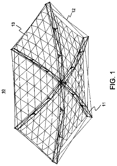
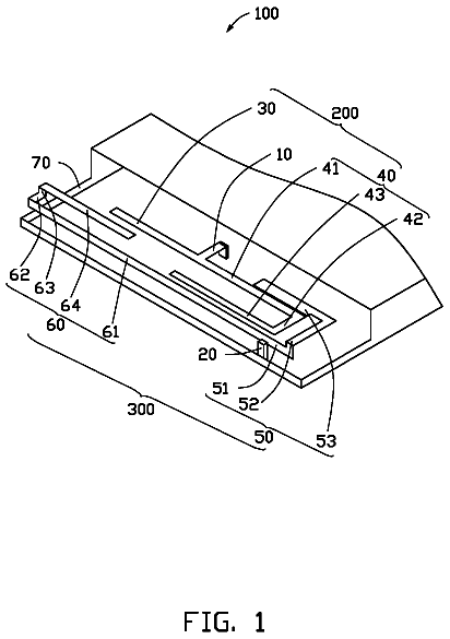
An antenna structure includes a feed portion, a ground portion, a primary antenna, a secondary antenna, and a metal portion connected to the ground portion.
US 9,774,100 B2 · Assignee: YAZAKI CORPORATION · Inventors: Shinohara; Junya et al.
Sheet 1 of 25 from the published document. All sheets in the USPTO PDF
A terminal fitting includes a terminal connecting portion and an electric wire connecting portion. A water stop member is affixed to an inner wall surface of the electric wire connecting portion before crimping process and suppresses entering of water between the electric wire connecting portion and a core wire of the electric wire after the crimping. The electric wire connecting portion is formed into a U-shape by raising the first barrel piece and the second barrel piece from both ends of the bottom. The distal end of the first barrel piece is bent toward the second barrel piece, to form a gap between a slide contact surface on a descending second die and the distal end of the first barrel piece.
Conventionally known are crimp terminals including an electric wire connecting portion electrically connected to a core wire of an electric wire. Such a crimp terminal and an electric wire are crimped by a terminal crimping device, thereby being electrically connected to each other. Crimp terminals and terminal crimping devices of this kind need to prevent entering of water between the electric wire connecting portion and the core wire of the electric wire. Japanese Patent Application Laid-open No. 2014-182957 and Japanese Patent Application Laid-open No. 2014-182958, for example, include a water stop part that blocks a gap between a barrel piece and an electric wire. The water stop part is formed by: affixing a water stop sheet made of butyl rubber and other materials to the inner surface of the barrel piece and caulking the electric wire set on the water stop sheet with the barrel piec
1 of 25 drawing sheets so far from the published document, cropped to the drawing. Every sheet is in the USPTO PDF.
What the patent claimed, word for word. All of it is now free to use.
The present application claims priority to and incorporates by reference the entire contents of Japanese Patent Application No. 2015-244872 filed in Japan on Dec. 16, 2015.
The present invention relates to a crimp terminal and a terminal crimping device.
Conventionally known are crimp terminals including an electric wire connecting portion electrically connected to a core wire of an electric wire. Such a crimp terminal and an electric wire are crimped by a terminal crimping device, thereby being electrically connected to each other. Crimp terminals and terminal crimping devices of this kind need to prevent entering of water between the electric wire connecting portion and the core wire of the electric wire. Japanese Patent Application Laid-open No. 2014-182957 and Japanese Patent Application Laid-open No. 2014-182958, for example, include a water stop part that blocks a gap between a barrel piece and an electric wire. The water stop part is formed by: affixing a water stop sheet made of butyl rubber and other materials to the inner surface of the barrel piece and caulking the electric wire set on the water stop sheet with the barrel piece. The techniques described in Japanese Patent Application Laid-open No. 2014-160591 and Japanese Patent Application Laid-open No. 2012-69449 include a layer (insulating coating portion) made of an insulating resin, such as polyethylene and butyl rubber, instead of the water stop sheet. The insulating resin layer serves as the water stop part after the barrel piece is caulked.
Various types of structures to caulk an electric wire sandwiched by two barrel pieces are known, including the structures described in Japanese Patent Application Laid-open No. 2014-182957, Japanese Patent Application Laid-open No. 2014-182958, and Japanese Patent Application Laid-open No. 2014-182954. In these structures, a first barrel piece (inner barrel piece) is wound around and crimped to the electric wire, and a second barrel piece (outer barrel piece) is wound around and crimped to the electric wire and the first barrel piece. In these caulking structures, the end surfaces of the respective barrel pieces may possibly come into contact with each other in the caulking process, resulting in deformation of the barrel pieces, displacement of the electric wire connecting portion, and other faults. As a result, a desired crimped structure fails to be provided, thereby deteriorating the water stop performance in the electric wire connecting portion. To increase the affixing strength between the barrel pieces and the core wire, the technique described in Japanese Patent Application Laid-open No. 2014-182954 bends the distal end of the first barrel piece such that the distal end sticks into the core wire. This structure fails to form a gap into which the second barrel piece can enter between the bent portion and the slide contact surface. As a result, the bent portion may possibly serve as a part coming into contact with the second barrel piece.
The present invention aims to provide a crimp terminal having high water stop performance in an electric wire connecting portion and a terminal crimping device that can enhance the water stop performance in the electric wire connecting portion.
In order to achieve the above mentioned object, a crimp terminal according to one aspect of the present invention includes a terminal fitting that includes a terminal connecting portion electrically connected to a counterpart terminal, an electric wire connecting portion electrically connected to an end of an electric wire placed on an inner wall surface side of the electric wire connecting portion by crimping process performed with the electric wire connecting portion sandwiched between a first die and a second die, and a coupling portion that couples the terminal connecting portion and the electric wire connecting portion, the electric wire connecting portion being divided into a bottom on which the end of the electric wire is placed during the crimping process, a first barrel piece extending from one end of the bottom, wound around the end of the electric wire, and positioned on an inner side, and a second barrel piece extending from the other end of the bottom longer than the first barrel piece, wound around the end of the electric wire and the first barrel piece, and positioned on an outer side; and a water stop member that is affixed to the inner wall surface of the electric wire connecting portion before the crimping process is performed and that is configured to suppress entering of water between the electric wire connecting portion and a core wire at a distal end of the electric wire after the crimping process is completed, wherein the electric wire connecting portion is formed into a U-shape by raising the first barrel piece and the second barrel piece from both ends of the bottom before the crimping process is performed, and a distal end of the first barrel piece in an extending direction in the electric wire connecting portion having a U-shape is bent toward the second barrel piece, to form a gap between the distal end of the first barrel piece and a slide contact surface for the first barrel piece on the second die that descends.
According to another aspect of the present invention, in the crimp terminal, it is preferable that the distal end of the first barrel piece is bent such that the gap is larger than at least the thickness of a distal end of the second barrel piece in an extending direction.
According to still another aspect of the present invention, in the crimp terminal, it is preferable that when the water stop member is affixed to a distal end of the second barrel piece, the distal end of the first barrel piece is bent such that the gap is larger than at least the sum of the thickness of the distal end of the second barrel piece and the thickness of the water stop member.
According to still another aspect of the present invention, in the crimp terminal, it is preferable that the inner wall surface of the second barrel piece has a first groove formed at a part overlapping with an outer wall surface of the first barrel piece after the crimping process is completed and is configured to be filled with part of the affixed water stop member, and the water stop member in the first groove forms into a water stop area that suppresses entering of water between the electric wire connecting portion and the core wire at the distal end of the electric wire after the crimping process is completed.
According to still another aspect of the present invention, in the crimp terminal, it is preferable that the water stop member is affixed to an affixing area on the inner wall surface of the second barrel piece, the affixing area being determined such that the water stop member on the inner wall surface of the second barrel piece is capable of covering the outer wall surface of the distal end of the first barrel piece after the crimping process is completed.
According to still another aspect of the present invention, a terminal crimping device includes a terminal supplying device configured to transfer a crimp terminal to a crimping position at which the crimp terminal is crimped to an electric wire; a crimping device configured to crimp the crimp terminal transferred to the crimping position to an end of the electric wire using a first die and a second die; and a driving device configured to reduce a gap between the first die and the second die during crimping process and increases the gap between the first die and the second die after the crimping process is completed, wherein the crimp terminal comprises a terminal fitting that includes a terminal connecting portion electrically connected to a counterpart terminal, an electric wire connecting portion electrically connected to the end of the electric wire placed on an inner wall surface side of the electric wire connecting portion by the crimping process, and a coupling portion that couples the terminal connecting portion and the electric wire connecting portion, the electric wire connecting portion being divided into a bottom on which the end of the electric wire is placed during the crimping process, a first barrel piece extending from one end of the bottom, wound around the end of the electric wire, and positioned on an inner side, and a second barrel piece extending from the other end of the bottom longer than the first barrel piece, wound around the end of the electric wire and the first barrel piece, and positioned on an outer side, and a water stop member that is affixed to the inner wall surface of the electric wire connecting portion before the crimping process is performed and configured to suppress entering of water between the electric wire connecting portion and a core wire at a distal end of the electric wire after the crimping process is completed, the first die and the second die are a lower die and an upper die, respectively, that sandwich the electric wire connecting portion formed into a U-shape by raising the first barrel piece and the second barrel piece from both ends of the bottom and the end of the electric wire surrounded by the bottom, the first barrel piece, and the second barrel piece, to crimp the end of the electric wire to the electric wire connecting portion, the first die has a recessed surface recessed downward and on which the bottom is placed, the second die has a recessed portion arranged facing the recessed surface and having a first wall surface and a second wall surface that slide on and apply pressure to the first barrel piece and the second barrel piece, respectively, when the second die descends toward the first die, to crimp the first barrel piece and the second barrel piece to the end of the electric wire, the first wall surface and the second wall surface each have a vertical surface extending along a moving direction of the second die and an arc surface that is connected to the vertical surface and configured to thrust the first barrel piece and the second barrel piece sliding along the vertical surface toward the end of the electric wire, and the recessed portion is formed such that a timing at which the first barrel piece moves from the vertical surface to the arc surface of the first wall surface is earlier than a timing at which the second barrel piece moves from the second wall surface side to the arc surface of the first wall surface.
According to still another aspect of the present invention, in the terminal crimping device, it is preferable that a radius of curvature of the arc surface of the first wall surface in the recessed portion is larger than a radius of curvature of the arc surface of the second wall surface so as to enable a distal end of the second barrel piece in an extending direction to enter between the first barrel piece and the first wall surface in the crimping process.
According to still another aspect of the present invention, in the terminal crimping device, it is preferable that a distal end of the first barrel piece in an extending direction in the electric wire connecting portion having a U-shape of the crimp terminal is bent toward the second barrel piece, to form a gap between the vertical surface of the first wall surface on the second die that descends and the distal end of the first barrel piece.
The above and other objects, features, advantages and technical and industrial significance of this invention will be better understood by reading the following detailed description of presently preferred embodiments of the invention, when considered in connection with the accompanying drawings.
FIG. 1 is a perspective view of a crimp terminal according to an embodiment and illustrates a state where the crimp terminal is yet to be connected to an electric wire;
FIG. 2 is a side view of the crimp terminal according to the embodiment and illustrates a state where an electric wire connecting portion is formed into a U-shape;
FIG. 3 is a perspective view of the crimp terminal after completion of crimping according to the embodiment;
FIG. 4 is a side view of the crimp terminal after completion of crimping according to the embodiment;
FIG. 5 is a perspective view of a terminal fitting of the crimp terminal according to the embodiment and illustrates a state where a water stop member is yet to be affixed;
FIG. 6 is a top view of the terminal fitting of the crimp terminal according to the embodiment and illustrates a state where the water stop member is yet to be affixed;
FIG. 7 is a view of a sectional part of the electric wire connecting portion along line X-X in FIG. 2 ;
FIG. 8 is a view of a sectional part of the electric wire connecting portion along line Y 1 -Y 1 in FIG. 4 ;
FIG. 9 is a view of a sectional part of the electric wire connecting portion along line Y 2 -Y 2 in FIG. 4 ;
FIG. 10 is a view of a sectional part of the electric wire connecting portion along line Y 3 -Y 3 in FIG. 4 ;
FIG. 11 is a view for explaining the electric wire connecting portion to which the water stop member is yet to be affixed;
FIG. 12 is a top view of the crimp terminal according to the embodiment and illustrates a state where the water stop member is affixed;
FIG. 13 is a view for explaining the electric wire connecting portion yet to be formed into a U-shape and the water stop member;
FIG. 14 is a view for explaining a terminal chain body;
FIG. 15 is a view for explaining a terminal crimping device according to the embodiment;
FIG. 16 is a perspective view for explaining a first die and a second die according to the embodiment;
FIG. 17 is a front view for explaining the first die and the second die according to the embodiment;
FIG. 18 is a diagram of a crimping process performed at a part along line Y 1 -Y 1 in FIG. 4 ;
FIG. 19 is a diagram of a crimping process performed at a part along line Y 2 -Y 2 in FIG. 4 ;
FIG. 20 is a diagram of a crimping process performed at a part along line Y 3 -Y 3 in FIG. 4 ;
FIG. 21 is a view for explaining a state of holding a terminal connecting portion by a rotation suppressor;
FIG. 22 is a view for explaining a rotation suppressing structure for the electric wire connecting portion by the second die (crimper);
FIG. 23 is a view for explaining a sliding range and a remaining range in the water stop member;
FIG. 24 is a view of an example of an accommodation groove according to the embodiment;
FIG. 25 is a view of a modification of the accommodation groove;
FIG. 26 is a view of another modification of the accommodation groove;
FIG. 27 is a view of still another modification of the accommodation groove;
FIG. 28 is a view of still another modification of the accommodation groove;
FIG. 29 is a view of still another modification of the accommodation groove; and
FIG. 30 is a view for explaining an engagement structure and illustrates a sectional part of the electric wire connecting portion along line Y 2 -Y 2 in FIG. 4 .
Exemplary embodiments of a crimp terminal and a terminal crimping device according to the present invention are described below in greater detail with reference to the accompanying drawings. The embodiments are not intended to limit the invention. Embodiments
An embodiment of the crimp terminal and the terminal crimping device according to the present invention is described with reference to FIGS. 1 to 30 .
The crimp terminal according to the present embodiment is represented by reference numeral 1 in FIGS. 1 to 4 . The crimp terminal 1 is electrically connected to an electric wire 50 and electrically connected to a counterpart terminal (not illustrated) while being integrated with the electric wire 50 . At an end of the electric wire 50 , a cover 52 is removed by a predetermined length so as to expose a core wire 51 by the predetermined length. The core wire 51 may be an aggregate of a plurality of wires or a solid wire, such as a coaxial cable. To electrically connect the crimp terminal 1 to the electric wire 50 , the crimp terminal 1 is crimped to the end of the electric wire 50 . As a result, the crimp terminal 1 is electrically connected to the core wire 51 at the exposed distal end (hereinafter, simply referred to as a “core wire at the distal end”).
Specifically, the crimp terminal 1 includes a terminal fitting 10 and a water stop member 20 .
The terminal fitting 10 is a main part of the crimp terminal 1 . The terminal fitting 10 is made of a conductive metal plate (e.g., a copper plate) and formed into a predetermined shape that enables the terminal fitting 10 to be connected to the counterpart terminal and the electric wire 50 . As illustrated in FIGS. 5 and 6 , the terminal fitting 10 includes a terminal connecting portion 11 and an electric wire connecting portion 12 . The terminal connecting portion 11 is electrically connected to the counterpart terminal. The electric wire connecting portion 12 is electrically connected to the electric wire 50 . The terminal connecting portion 11 and the electric wire connecting portion 12 are coupled to each other by a coupling portion 13 provided therebetween.
The terminal fitting 10 may be a male terminal or a female terminal. In a case where the terminal fitting 10 is a male terminal, the terminal connecting portion 11 is formed into a male shape. In a case where the terminal fitting 10 is a female terminal, the terminal connecting portion 11 is formed into a female shape. In the present embodiment, the terminal fitting 10 is a female terminal, for example.
In the crimp terminal 1 , a connection direction (insertion direction) to the counterpart terminal is defined as a first direction L corresponding to a longitudinal direction. A parallel arrangement direction, which will be described later, of the crimp terminal 1 is defined as a second direction W corresponding to a width direction of the crimp terminal 1 . In the crimp terminal 1 , a direction orthogonal to the first direction L and the second direction W is defined as a third direction H corresponding to a height direction.
The electric wire connecting portion 12 is a formed into a plate shape first ( FIGS. 5 and 6 ). The electric wire connecting portion 12 is subjected to predetermined processing, which will be described later, thereby being formed into a U-shape corresponding to a state just before being connected to the electric wire 50 ( FIGS. 1 and 7 ). The electric wire connecting portion 12 is wound around the electric wire 50 with the end of the electric wire 50 placed thereon. The electric wire connecting portion 12 is thus crimped to the end of the electric wire 50 , thereby coming into contact with the core wire 51 at the distal end.
The electric wire connecting portion 12 can be divided into an area of a bottom 14 , an area of a first barrel piece 15 , and an area of a second barrel piece 16 . The bottom 14 is a part serving as a bottom wall of the U-shaped electric wire connecting portion 12 . In crimping, the end of the electric wire 50 is placed on the bottom 14 . The first barrel piece 15 and the second barrel piece 16 are parts serving as side walls of the U-shaped electric wire connecting portion 12 . The first barrel piece 15 and the second barrel piece 16 extend at both ends of the bottom 14 in the second direction W. In the U-shaped electric wire connecting portion 12 , the first barrel piece 15 and the second barrel piece 16 extend in a manner surrounding the end of the electric wire 50 from both ends of the bottom 14 .
The first barrel piece 15 and the second barrel piece 16 are formed such that one of the lengths from the proximal ends of the bottom 14 side to the end surfaces of a distal end 15 a and a distal end 16 a is longer than the other. With this structure, one of the distal ends 15 a and 16 a of the first barrel piece 15 and the second barrel piece 16 , respectively, extends longer than the other in the third direction H in the U-shaped electric wire connecting portion 12 . In this example, the second barrel piece 16 extends longer than the first barrel piece 15 from the bottom 14 (refer to FIGS. 1 and 7 ). With this structure, the electric wire connecting portion 12 has an area in which the first barrel piece 15 and the second barrel piece 16 overlap with each other (hereinafter, referred to as an “overlapping area”) after crimping is completed (hereinafter, referred to as “after completion of crimping”) ( FIGS. 8 to 10 ). Specifically, the overlapping area is an area in which the outer wall surface of the first barrel piece 15 faces the inner wall surface of the second barrel piece 16 after completion of crimping. In other words, the first barrel piece 15 of the electric wire connecting portion 12 is a barrel piece wound around the end of the electric wire 50 on the inner side, and the second barrel piece 16 is a barrel piece wound around the end of the electric wire 50 on the outer side. In crimping, the first barrel piece 15 is wound around the outer periphery of the end of the electric wire 50 , and the second barrel piece 16 is wound so as to cover the end of the electric wire 50 and the first barrel piece 15 from the outer periphery side. As described above, the first barrel piece 15 and the second barrel piece 16 of the electric wire connecting portion 12 are caulked to the end of the electric wire 50 .
The end of the electric wire 50 is inserted into a U-shaped internal space from an opening of the U-shape of the electric wire connecting portion 12 (opening formed between the respective end surfaces of the distal ends 15 a and 16 a ). To facilitate insertion of the end of the electric wire 50 , the gap between the first barrel piece 15 and the second barrel piece 16 of the electric wire connecting portion 12 increases from the bottom 14 side to the opening side (the distal ends 15 a and 16 a side).
The electric wire connecting portion 12 can be further divided into an area of a core wire crimping portion 12 A, an area of a cover crimping portion 12 B, and an area of a coupling crimping portion 12 C ( FIGS. 2 and 4 to 6 ). The core wire crimping portion 12 A is a part crimped to the core wire 51 at the distal end and coupled to the coupling portion 13 . The cover crimping portion 12 B is a part crimped to the cover 52 coupled to the proximal end of the exposed part of the core wire 51 at the distal end. The coupling crimping portion 12 C is a part that couples the core wire crimping portion 12 A and the cover crimping portion 12 B and that is crimped to the end of the electric wire 50 .
The electric wire connecting portion 12 has a core wire holding area (hereinafter, referred to as a “serration area”) 17 that holds the crimped core wire 51 at the distal end on its inner wall surface (wall surface that covers the electric wire 50 ) ( FIG. 11 ). The serration area 17 is provided to at least a part wound around the core wire 51 at the distal end in the inner wall surface of the electric wire connecting portion 12 . The serration area 17 in this example is formed so as to cover the entire core wire 51 at the distal end. The serration area 17 in the first direction L is formed between a part closer to the terminal connecting portion 11 than the distal end position of the core wire 51 at the distal end placed on the inner wall surface and a part on which the cover 52 is placed. The serration area 17 in the second direction W is formed between a part on the distal end 15 a of the first barrel piece 15 and a part of the second barrel piece 16 that comes into contact with at least the core wire 51 at the distal end after completion of crimping. The serration area 17 in this example is provided to a part closer to the distal end 16 a than the part that comes into contact with the core wire 51 at the distal end. Specifically, in the serration area 17 according to the present embodiment, a plurality of recesses, a plurality of protrusions, or a plurality of combinations of recesses and protrusions are arrayed in a rectangular shape. The recesses and the protrusions increase the contact area between the electric wire connecting portion 12 and the core wire 51 at the distal end and the adhesive strength therebetween. In this example, the rectangular serration area 17 is composed of a plurality of recesses 17 a.
The electric wire connecting portion 12 and the core wire 51 at the distal end need to be electrically connected to each other. Entering of water therebetween is undesirable because it may possibly reduce the durability. Let us assume a case where the electric wire connecting portion 12 and the core wire 51 are made of different types of metal materials having different ionization tendencies (e.g., copper and aluminum), for example. In this case, entering of water therebetween may possibly cause corrosion especially in aluminum. To address this, the crimp terminal 1 is provided with the water stop member 20 that suppresses entering of water between the electric wire connecting portion 12 and the core wire 51 at the distal end ( FIGS. 12 and 13 ). The water stop member 20 is a sheet-like member made mainly of an adhesive, such as a modified acrylic adhesive. The water stop member 20 , for example, is a sheet-like nonwoven fabric impregnated with the adhesive and has an adhesive effect on both surfaces of the sheet.
The water stop member 20 has a first water stop area 21 , a second water stop area 22 , and a third water stop area 23 formed after completion of crimping ( FIGS. 8 to 10 ). To embody the arrangement of the first to the third water stop areas 21 to 23 , the water stop member 20 is formed into a predetermined shape and affixed to the inner wall surface of the plate-like electric wire connecting portion 12 illustrated in FIG. 6 .
The first water stop area 21 is an area where the water stop member 20 is interposed between at least the outer wall surface of the first barrel piece 15 and the inner wall surface of the second barrel piece 16 (that is, the overlapping area) after completion of crimping ( FIGS. 8 to 10 ). The first water stop area 21 suppresses entering of water between the electric wire connecting portion 12 and the core wire 51 at the distal end from the space between the outer wall surface and the inner wall surface. The first water stop area 21 extends between a part closer to the terminal connecting portion 11 than the distal end position of the core wire 51 at the distal end and a part closer to the cover 52 than the proximal end of the core wire 51 at the distal end. The first water stop area 21 is formed by a first water stop portion 24 of the water stop member 20 ( FIG. 13 ).
The first water stop portion 24 is arranged on the second barrel piece 16 between the distal end 16 a and the bottom 14 . The first water stop portion 24 extends from a part closer to the terminal connecting portion 11 than the distal end position of the core wire 51 at the distal end and a part closer to the cover 52 than the proximal end of the core wire 51 at the distal end. The part of the first water stop portion 24 on the bottom 14 side extends to a position where it covers the part of the serration area 17 on the second barrel piece 16 side. With this structure, the first water stop area 21 in this example is formed not only in the overlapping area but also between the inner wall surface of the second barrel piece 16 and the core wire 51 at the distal end within a range of not interrupting electrical connection between the second barrel piece 16 and the core wire 51 at the distal end ( FIG. 9 ).
The second water stop area 22 is an area filled with the water stop member 20 in at least the inner part of the electric wire connecting portion 12 formed after completion of crimping on the side closer to the terminal connecting portion 11 than the distal end position of the core wire 51 at the distal end ( FIG. 8 ). The second water stop area 22 suppresses entering of water between the electric wire connecting portion 12 and the core wire 51 at the distal end from the terminal connecting portion 11 side. The second water stop area 22 is mainly formed by a second water stop portion 25 of the water stop member 20 ( FIG. 13 ).
The second water stop portion 25 is arranged between the distal end 15 a side of the first barrel piece 15 and the first water stop portion 24 . The second water stop portion 25 extends from a part closer to the terminal connecting portion 11 than the distal end position of the core wire 51 at the distal end and a part corresponding to the distal end side of the core wire 51 at the distal end. The second water stop portion 25 in this example is arranged in a manner overlapping with the distal end of the core wire 51 at the distal end. With this structure, the second water stop area 22 in this example covers the distal end of the core wire 51 with the water stop member 20 (second water stop portion 25 ). The second water stop portion 25 in this example is connected to the first water stop portion 24 . In other words, the second water stop area 22 in this example is formed by the second water stop portion 25 and the connection part of the first water stop portion 24 to the second water stop portion 25 (part closer to the bottom 14 than the overlapping area).
The third water stop area 23 is an area where the water stop member 20 is interposed between at least the inner wall surface of the electric wire connecting portion 12 (specifically, the cover crimping portion 12 B) and the cover 52 after completion of crimping ( FIG. 10 ). The third water stop area 23 suppresses entering of water between the electric wire connecting portion 12 and the core wire 51 at the distal end from the space between the inner wall surface and the cover 52 . The third water stop area 23 is mainly formed by a third water stop portion 26 of the water stop member 20 ( FIG. 13 ).
The third water stop portion 26 is arranged at a part wound around the cover 52 in the electric wire connecting portion 12 between the distal end 15 a side of the first barrel piece 15 and the first water stop portion 24 . The third water stop portion 26 in this example is connected to the first water stop portion 24 . In other words, the third water stop area 23 in this example is formed by the third water stop portion 26 and the connection part of the first water stop portion 24 to the third water stop portion 26 (part closer to the bottom 14 than the overlapping area).
The water stop member 20 having the shape described above is arranged on the inner wall surface of the electric wire connecting portion 12 . With this structure, the water stop member 20 serves as the first to the third water stop areas 21 to 23 connected to one another after completion of crimping. The first to the third water stop areas 21 to 23 prevent the end of the electric wire 50 from communicating with the outside in the electric wire connecting portion 12 . As a result, the water stop member 20 can suppress entering of water between the electric wire connecting portion 12 and the core wire 51 at the distal end.
The terminal fitting 10 described above is subjected to a pressing process performed on one metal plate, thereby being formed into the shape having the plate-like electric wire connecting portion 12 illustrated in FIG. 6 . In the following water stop member affixing process, the water stop member 20 is affixed to the plate-like electric wire connecting portion 12 . In the following folding process, the terminal connecting portion 11 and the U-shaped electric wire connecting portion 12 are formed in the terminal fitting 10 .
A plurality of crimp terminals 1 subjected to the processes described above are arranged in line and formed into a chain body (hereinafter, referred to as a “terminal chain body”) 30 ( FIG. 14 ). The terminal chain body 30 is an aggregate of the crimp terminals 1 arranged in parallel at regular intervals with themselves facing the same direction and connected to one another in a chain shape. In the terminal chain body 30 , one ends of all the crimp terminals 1 are connected by a connection piece 31 . The connection piece 31 is formed into a rectangular plate shape, for example, and arranged with a predetermined gap interposed between the connection piece 31 and the electric wire connecting portions 12 of all the crimp terminals 1 . Each bottom 14 of the electric wire connecting portions 12 is coupled to the connection piece 31 via respective rectangular plate-like coupling portion 32 , for example. The connection piece 31 has through holes (hereinafter, referred to as “terminal feeding holes”) 31 a formed at regular intervals in the feeding direction of the terminal chain body 30 . The terminal feeding holes 31 a are used to feed the terminal chain body 30 to the crimping position in a terminal crimping device 100 . The terminal chain body 30 formed in this manner is placed in the terminal crimping device 100 in a manner wound like a reel (not illustrated). After being crimped to the electric wire 50 , the crimp terminal 1 is cut off from the terminal chain body 30 .
The following describes the terminal crimping device 100 .
As illustrated in FIG. 15 , the terminal crimping device 100 includes a terminal supplying device 101 , a crimping device 102 , and a driving device 103 . The terminal supplying device 101 transfers the crimp terminal 1 to a predetermined crimping position. The crimping device 102 crimps the crimp terminal 1 to the electric wire 50 at the crimping position. The driving device 103 operates the terminal supplying device 101 and the crimping device 102 . The terminal supplying device 101 and the crimping device 102 are referred to as an applicator in this technical field.
The terminal supplying device 101 draws out the leading crimp terminal 1 positioned on the outer periphery of the terminal chain body 30 wound like a reel and sequentially transfers it to the crimping position. After finishing crimping the leading crimp terminal 1 to the electric wire 50 and cutting it off from the terminal chain body 30 , the terminal supplying device 101 transfers another leading crimp terminal 1 to the crimping position. The terminal supplying device 101 sequentially repeats the operation described above every time it performs crimping and cutting.
The terminal supplying device 101 has a configuration publicly known in this technical field and includes a terminal feeding member 101 a and a power transmission mechanism 101 b . The terminal feeding member 101 a is inserted into the terminal feeding hole 31 a in the connection piece 31 . The power transmission mechanism 101 b drives the terminal feeding member 101 a with the power of the driving device 103 . The power transmission mechanism 101 b serves as a link mechanism linked with a crimping operation (e.g., an up-and-down movement of a ram 114 A, which will be described later) of the crimping device 102 . The terminal supplying device 101 in this example is linked with the crimping operation of the crimping device 102 to drive the terminal feeding member 101 a in the vertical direction and the horizontal direction. The terminal supplying device 101 thus transfers the crimp terminal 1 to the crimping position.
The crimping device 102 crimps the transferred crimp terminal 1 to the electric wire 50 and cuts off the crimp terminal 1 from the terminal chain body 30 . The crimping device 102 includes a crimping machine 110 and a terminal cutting machine 120 .
The crimping machine 110 is a device that caulks the crimp terminal 1 transferred to the crimping position to the end of the electric wire 50 , thereby crimping the crimp terminal 1 to the electric wire 50 . The crimping machine 110 in this example caulks the first barrel piece 15 and the second barrel piece 16 of the crimp terminal 1 to the core wire 51 at the distal end and the cover 52 of the electric wire 50 , thereby crimping the crimp terminal 1 to the electric wire 50 . The crimping machine 110 includes a frame 111 , a pair of first die 112 and second die 113 , and a power transmission mechanism 114 .
The frame 111 includes a base 111 A, an anvil support 111 B, and a support (hereinafter, referred to as a “transmission unit support”) 111 C for the power transmission mechanism 114 . The base 111 A is fixed on a pedestal (not illustrated) on which the terminal crimping device 100 is placed, for example. The anvil support 111 B and the transmission unit support 111 C are fixed on the base 111 A. The transmission unit support 111 C is arranged behind (on the right side in the drawing in FIG. 15 ) and above (on the upper side in the drawing in FIG. 15 ) the anvil support 111 B. Specifically, the transmission unit support 111 C includes a standing portion 111 C.sub.1 and a ram support portion 111 C.sub.2. The standing portion 111 C.sub.1 is provided in a manner standing upward from the base 111 A behind the anvil support 111 B. The ram support portion 111 C.sub.2 is held by the upper part of the standing portion 111 C.sub.1. The ram support portion 111 C.sub.2 is a support that supports the ram 114 A, which will be described later, and is arranged above the anvil support 111 B with a predetermined gap interposed therebetween.
The first die 112 and the second die 113 are arranged in the vertical direction with a gap interposed therebetween. The first die 112 and the second die 113 are crimping dies that sandwich the crimp terminal 1 and the end of the electric wire 50 placed therebetween to crimp the crimp terminal 1 to the end of the electric wire 50 ( FIG. 16 ). The first die 112 includes two lower dies of a first anvil 112 A and a second anvil 112 B. The second die 113 includes two upper dies of a first crimper 113 A and a second crimper 113 B. The first anvil 112 A and the first crimper 113 A are arranged facing each other in the vertical direction. The first anvil 112 A and the first crimper 113 A reduces the gap therebetween, thereby crimping the U-shaped core wire crimping portion 12 A to the core wire 51 at the distal end. The second anvil 112 B and the second crimper 113 B are arranged facing each other in the vertical direction. The second anvil 112 B and the second crimper 113 B reduces the gap therebetween, thereby crimping the U-shaped cover crimping portion 12 B to the cover 52 .
The driving device 103 transmits its power to the power transmission mechanism 114 to reduce the gap between the first anvil 112 A and the first crimper 113 A and the gap between the second anvil 112 B and the second crimper 113 B in crimping. After the crimping, the driving device 103 increases the gap between the first anvil 112 A and the first crimper 113 A and the gap between the second anvil 112 B and the second crimper 113 B. In this example, the driving device 103 moves the second die 113 up and down with respect to the first die 112 , thereby moving the first crimper 113 A and the second crimper 113 B up and down simultaneously with respect to the first anvil 112 A and the second anvil 112 B. The first anvil 112 A and the second anvil 112 B and the first crimper 113 A and the second crimper 113 B may be separately formed bodies. In this case, the driving device 103 and the power transmission mechanism 114 may move the first crimper 113 A and the second crimper 113 B up and down separately. In this example, crimping of the core wire crimping portion 12 A is started by the first anvil 112 A and the first crimper 113 A first, and crimping of the cover crimping portion 12 B is then started by the second anvil 112 B and the second crimper 113 B.
The description continues in the full USPTO document.
About 7,171 words. The USPTO PDF has it with every drawing.
Fees are due 3.5, 7.5 and 11.5 years after grant. This patent expired on September 26, 2025, so the fee marked "not paid" was the one that went unpaid.
CRIMP TERMINAL AND TERMINAL CRIMPING DEVICE
Filed Dec 2016 · published Jun 2017Crimp terminal and terminal crimping device
Filed Dec 2016 · granted Sep 2017Earlier publications, parents and continuations. None of them can still be enforced, or this patent would not be listed.
Prior art cited by the examiner or applicant. Useful when you check your own idea for novelty.
Everything on this page comes from the documents linked above.