 Lapsed, fee not paid5 drawings
Software & Apps · US 9,772,919 B2
Automation of D-bus communication testing for bluetooth profiles
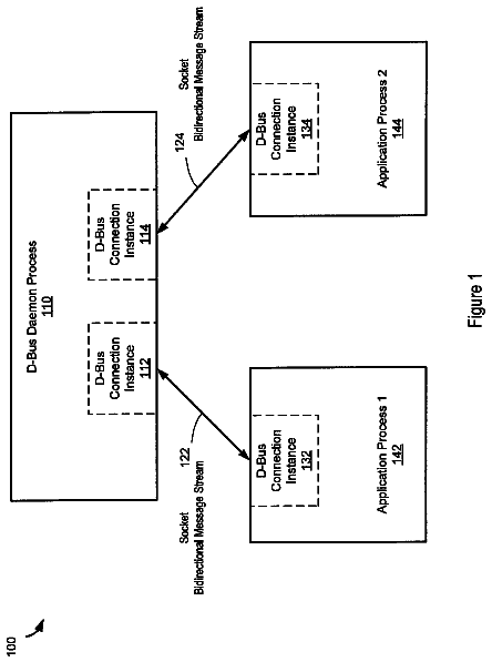
An electronic control unit (ECU) is tested by an automated D-bus testing tool in a first device.
US 9,772,931 B2 · Assignee: FUJITSU LIMITED · Inventors: Copos; Bogdan et al.
Sheet 1 of 10 from the published document. All sheets in the USPTO PDF
A method includes selecting a set of printable characters as one or more test inputs for a binary module having no known valid input. The method also includes executing the binary module with the set of printable characters as the one or more test inputs for the binary module. The method also includes determining a number of instructions executed by the binary module responsive to being executed with the set of printable characters. The method also includes generating set data including the one or more printable characters associated with the number of instructions executed for each of the one or more printable characters. The method also includes analyzing the set data to identify one or more printable characters as one or more valid inputs for the binary module based on a comparison of the number of instructions associated with the one or more printable characters and a threshold range.
Efficient testing of a binary file may be improved by knowledge of which inputs are valid for the binary file. The binary file may include code and routines that a human may interpret as text. However, the text included in the code and routines of the binary file are not human-readable. It is impossible for human testers of the binary file to determine valid inputs for the binary file by reviewing the code and routines of the binary file because the code and routines are not human readable. As a result, the human testers may review specifications, documentation or source code associated with the binary file in order to determine which inputs are valid for the binary file. These valid inputs may then be used to achieve more efficient testing of the binary file.
1 of 10 drawing sheets so far from the published document, cropped to the drawing. Every sheet is in the USPTO PDF.
What the patent claimed, word for word. All of it is now free to use.
The embodiments discussed herein are related to determining a valid input for an unknown binary module.
Efficient testing of a binary file may be improved by knowledge of which inputs are valid for the binary file. The binary file may include code and routines that a human may interpret as text. However, the text included in the code and routines of the binary file are not human-readable. It is impossible for human testers of the binary file to determine valid inputs for the binary file by reviewing the code and routines of the binary file because the code and routines are not human readable. As a result, the human testers may review specifications, documentation or source code associated with the binary file in order to determine which inputs are valid for the binary file. These valid inputs may then be used to achieve more efficient testing of the binary file.
According to an aspect of an embodiment, a method includes selecting a set of printable characters as one or more test inputs for a binary module having no known valid input. The method also includes executing the binary module with the set of printable characters as the one or more test inputs for the binary module. The method also includes determining, for each of the printable characters included in the set of printable characters, a number of instructions executed by the binary module responsive to being executed with the set of printable characters. The method also includes generating set data including the one or more printable characters associated with the number of instructions executed for each of the one or more printable characters. The method also includes analyzing the set data to identify one or more printable characters as one or more valid inputs for the binary module based on a comparison of the number of instructions associated with the one or more printable characters and a threshold range.
The object and advantages of the embodiments will be realized and achieved at least by the elements, features, and combinations particularly pointed out in the claims.
It is to be understood that both the foregoing general description and the following detailed description are exemplary and explanatory and are not restrictive of the invention, as claimed.
Example embodiments will be described and explained with additional specificity and detail through the use of the accompanying drawings in which:
FIG. 1A is a block diagram of an example operating environment for a valid input determination system;
FIG. 1B is a block diagram of an example valid input determination system;
FIG. 2A is a block diagram depicting an example of building a string in series over multiple iterations;
FIG. 2B is a block diagram depicting an example of building a string in parallel over multiple iterations;
FIG. 3 is a block diagram of an example system to determine a valid input for an unknown binary module;
FIG. 4 is a block diagram of a system to determine a size of a valid input for an unknown binary module; and
FIGS. 5A, 5B, 5C and 5D show example flow diagrams of a method to determine a valid input for an unknown binary module.
The embodiments discussed herein are related to determining a valid input for an unknown binary module. The valid input may include a valid input string for the unknown binary module. The valid input string may include one or more valid characters. The valid input string and the valid characters are described in more detail below.
The unknown binary module may include a binary file for a program. The binary file may include code and routines encoded in binary form and stored on a non-transitory computer-readable storage medium for execution by a processing device. Although the code and routines of the binary file may include portions that may be interpreted by a human as text, the code and routines of the binary file are not human-readable.
The binary module may be described as “unknown” because a human tester may not know any valid inputs for the binary file included in the binary module. For example, the specification, documentation or source code associated with the binary file may not be available to the human tester of the binary module, and so, the tester may not be able to determine valid inputs for the binary file included in the binary module.
Currently, there is no acceptable method to determine a valid input for an unknown binary module. There are some requirements for being considered an acceptable method for determining a valid input for an unknown binary module. A first requirement may include consistently covering a high percentage of the code and routines included in the binary file (excluding dead code) of the unknown binary module. For example, one or more test inputs selected for testing the binary file may cover one hundred percent or near one hundred percent of the code and routines for the binary file (e.g., ninety percent to one hundred percent of the binary file, excluding dead code and routines). Some of the existing methods rely on generation of random test inputs for testing the unknown binary file. Unfortunately, testing methods that include generation of random test inputs for testing the unknown binary file are unable to consistently cover a high percentage of the code and routines for the unknown binary file because randomly generated test inputs are inherently incompatible with the goal of consistently covering a high percentage of the code and routines for the unknown binary file. As a result, these existing methods are not able to consistently cover a high percentage of the code and routines for the binary file, and so, these methods are not considered acceptable.
Another requirement for being considered an acceptable method for determining valid inputs for unknown binary modules may include the ability to be effectively implemented without a specification, documentation or source code associated with the binary file. This requirement may be beneficial in the field of autonomous software security where it is beneficial for a computer system to automatically determine vulnerabilities in software. In some situations, the binary file may be available to human testers of the binary module, but the specification, documentation and source code associated with the binary file may be unavailable. Some existing methods attempt to determine valid inputs for unknown binary modules. However, these methods rely on randomly generated test inputs or have other deficiencies.
Another requirement for being considered an acceptable method for determining valid inputs for unknown binary modules may include platform independence. Platform independence may beneficially improve the portability of the methodology as well as provide other benefits.
As mentioned above, methods exist that attempt to determine valid inputs for unknown binary modules. Unfortunately, these methods have numerous deficiencies that prevent them from being considered acceptable.
One such method may be referred to as a “symbolic execution.” The symbolic execution approach includes determining inputs for the binary file included in the unknown binary module which may drive the program along various execution paths including possibly crashing the program. This approach may be successful in some isolated instances. However, one deficiency associated with the symbolic execution approach is that the source file associated with the binary module may be needed to implement this approach. In some instances the source file is unavailable. As a result, in some instances implementation of the symbolic execution approach is not possible since the source file is needed but unavailable, and the symbolic execution approach is not considered an acceptable methodology. Another deficiency of the symbolic execution approach is that it does not scale well. The symbolic execution approach also does not work with many common scenarios. For example, the symbolic execution approach has known problems working with programs that include floating point arithmetic or when the constraints on the input gathered during execution of the program are non-linear. For these reasons and others, the symbolic execution approach is not an acceptable method for determining valid inputs for unknown binary modules.
Another approach is known as a “black-box fuzzing.” This approach may include selecting a string and randomly altering the string. The string may be fed to the binary module as an input after each alteration. Although this approach may work given enough time, most of the inputs generated by black-box fuzzing are invalid inputs. This is problematic since valid inputs are needed in order to mutate and identify additional valid inputs. An additional problem associated with black-box fuzzing is that this approach does not guarantee high coverage of the binary file included in the unknown binary module since it is reliant on random inputs, and so, it is impossible to know whether the results of implementing black-box fuzzing achieve high coverage.
Another approach is known as “white-box fuzzing.” The white-box fuzzing approach is similar to black-box fuzzing, with the exception that valid inputs are used to gather symbolic constraints, which may then be analyzed to produce test inputs. The white-box fuzzing approach may be considered an improvement over black-box fuzzing since it includes at least some inputs that are not arrived at randomly. However, the white-box approach requires valid inputs as a prerequisite before it may be implemented to determine test input. In some instances valid inputs will not be available as seeds for the white-box fuzzing approach. For this reason, the white-box fuzzing approach implemented by itself is unable to solve the problem of determining valid inputs for unknown binary modules.
Another approach is known as “unit testing,” in which the code for a program is divided into units and tested systematically. Although unit testing may be able to achieve high coverage testing of the binary file in some instances, this approach always requires source files or other documentation associated with the binary file such as the specification for the program. Without this information, unit testing may not be implemented. As such, the unit testing approach is unable to solve the problem of determining valid inputs for unknown binary modules since it requires source files or some other documentation. Another deficiency associated with the unit testing approach is that it is platform dependent. The unit testing approach is also considered to be slow and expensive.
Another approach is known as “specification-based testing”. However, as the name implies, the specification-based testing approach always requires source files or other documentation associated with the binary file such as the specification for the program. As such, this approach is unable to solve the problem of determining valid inputs for unknown binary modules since it requires source files or some other documentation. Similar to unit testing, the specification-based testing approach is also platform dependent and considered to be slow and expensive.
Other approaches may include “reverse code engineering.” These approaches may include: the “information exchange analysis” approach; the “disassembly” approach; and the “decompilation” approach. The information exchange analysis approach may not be effective if no information is exchanged by the program, and so, this approach is limited and not acceptable for this reason. The disassembly approach relies on a static or dynamic analysis of raw assembly code, which has a number of deficiencies. For example, static or dynamic analysis of raw assembly code is computationally expensive, imprecise, does not scale well and likely to introduce significant performance overheads. The decompilation approach attempts to reconstruct the source code associated with the binary file and proceed with the testing using the source code and the binary file. However, in practice the decompilation approach does not work in many situations and may render a source code file that is unusable or not high quality because in actuality it differs substantially from the original source code file it attempts to reconstruct.
The deficiencies of these and other systems may be overcome by a valid input determination system as described herein. In some implementations, the valid input determination system may not rely on random input generation. In this way, the valid input determination system may achieve high coverage of the program when determining one or more valid inputs. By comparison, techniques that rely on random input generation such as black-box fuzzing are unable to achieve high coverage when determining valid inputs. The valid input determination system may also be platform independent. In this way, the valid input determination system may be portable and used in a variety of operating environments. The valid input determination may also be successfully implemented without source code or documentation associated with the program or the binary file. In this way, the valid input determination system may be used for determining one or more valid inputs for an unknown binary module. The valid input determination may also be implemented without packet sniffing, bus analysis or any other methodology that relies on information exchange. In this way, the valid input determination system may be implemented without including use of reverse code engineering techniques.
The valid input determination system described herein may include a computing device. For example, the valid input determination system may include a personal computer, laptop, tablet computer, server or any processor-based computing device including server software. The valid input determination system may include a memory and a processor device. The processor device may be programmed to perform one or more steps of a method 500 described below with reference to FIGS. 5A, 5B, 5C and 5D . One or more example implementations of the valid input determination system will be described below.
The binary file of the unknown binary module may include a compiled version of a program. The program may accept one or more inputs. The inputs for the program may include one or more input strings. The program may include code and routines describing the functionality of the program. The code and routines of the program may also define which inputs are valid for the program and the binary file which is a compiled version of the program. Any input not defined as valid by the code and routines of the program may be an invalid input for the program and the binary file. An input which is invalid for the program and the binary file may also be invalid for the binary module which includes the binary file.
An input string for the program may include one or more indices and one or more printable characters. An index may include the position in the string at which the printable character occurs. For example, if the input strings that are accepted are “Hello” and “Howdy,” then the indices are “0,” “1,” “2,” “3” and “4.” In this example, the valid character at index “0” includes the printable character “H.” The valid characters at index “1” include the printable characters “e” and “o.” The valid characters at index “2” include “1” and “w.” The valid characters at index “3” include “1” and “d.” The valid characters at index “4” include “o” and “y.”
To be considered a valid input string, each of the characters included in the input string may be valid for the program or the binary file. For any given index of the valid input string, a majority of the printable characters available for use in the input string may be invalid. The valid input determination system may be configured to receive a set of printable characters and iteratively test the set of printable characters to determine if they are valid characters for different indexes of a valid input string for the unknown binary module.
For example, each of the printable characters included in the set of printable characters may be used as a test input for the unknown binary module for a given index of the input string. The test input may include a string of one or more printable characters. For instances where multiple printable characters are included in the test input, the different printable characters may be concatenated so that they are associated with different indices of the test input.
The memory of the valid input determination system may include a user space. The user space may include a portion of the memory in which user processes run. For example, the user space may include a portion of the memory where the unknown binary module may be executed using the test input to determine whether the test input is valid for the unknown binary module at the given index.
In some implementations, the valid input determination system may determine whether the test input is valid for the given index by analyzing a number of instructions executed in the user space when the unknown binary module is executed using a test input as the input for the unknown binary module. At a given index “i,” the unknown binary module may be provided with an input string including “i+1” characters to be used as test inputs for the unknown binary module. In some implementations, each of the printable characters included in the set of printable characters (except “[space]”) may be used as test inputs for the unknown binary module at the given index. The unknown binary module may execute instructions in the user space of the memory responsive to being executed using the test input as the input for the unknown binary module. The number of instructions executed for each test input may be monitored and recorded. The valid input determination system may analyze the number of instructions executed in the user space for each test input at the given index.
In some implementations, the valid input determination system may determine the number of instructions executed for a printable character at the given index. The number of executed instructions may be stored in the memory of the valid input determination system and associated with the printable character which resulted in that number of instructions being executed. The valid input determination system may determine whether the number of instructions executed for a particular printable character is outside a threshold range. In some implementations, this process may be repeated for each of the printable characters included in the set of printable characters since each of the printable characters included in the set may be used as a different test input. The valid input determination system may determine that printable characters associated with a number of instructions having value which is outside of the threshold range may be candidates for inclusion in a valid input for the unknown binary module. Printable characters associated with a number of instructions having a value inside of the threshold range may be excluded as candidates for inclusion in the valid input for the unknown binary module.
The threshold range may be determined by the valid input determination system based on a mode of the number of executed instructions and a testing constant. The mode may include the mode for the number of executed instructions. For example, the number of executed instructions may be stored in a set. The set may include one or more number values. The number values may represent the number of instructions executed for each input. For example, assume that a first input resulted in one hundred instructions being executed. The number value for the first input may be the number “one hundred.” The set may include other number values for other inputs. The mode may include the number value that appears most often in the set.
The testing constant may be referred to as “epsilon” or “the testing constant.” The testing constant may include any positive real number. The upper limit of the threshold range may be determined by the valid input determination system by adding the testing constant to the mode. The lower limit of the threshold range may be determined by the valid input determination system by subtracting the testing constant from the mode. As described in above, in some implementations the valid input determination system uses each printable character as a different test input for the unknown binary module and records a set of data including the number of instructions executed for each test input. The mode used to determine the threshold range may include the mode for the set of data including the number of instructions executed for each test input. In some implementations, the valid input determination system may determine that any printable character whose use as an input for the unknown binary module results in a number of executed instructions outside of the threshold range is a candidate for inclusion in the valid input string for the unknown binary module.
Embodiments of the present invention will be explained with reference to the accompanying drawings.
FIG. 1A is a block diagram of an example operating environment 100 for a valid input determination system, arranged in accordance with at least one embodiment described herein. The operating environment 100 may include the following elements: printable character data 120 ; a binary module 130 ; a valid input determination system 105 ; and valid input data 140 . The printable character data 120 and the binary module 130 may be inputted to the valid input determination system 105 . The valid input determination system 105 may output the valid input data 140 . The valid input determination system 105 may output the valid input data 140 responsive to receiving one or more of the printable character data 120 and the binary module 130 .
The printable character data 120 may include data describing one or more printable characters. For example, the printable character data 120 may include data describing the set of printable characters. In some implementations, the printable character data 120 may include a list of one or more printable characters.
The binary module 130 may include a binary file. The binary file may include a compiled version of a program. The program may include code and routines configured to provide functionality for a processor-based computing device. The binary module 130 may be described as an “unknown” binary module. The binary module 130 may be described as “unknown” because a human tester of the binary module 130 may not know any valid inputs for the binary file included in the binary module. For example, the specification, documentation or source code associated with the binary file may be unavailable, and so, the human tester may not be able to determine valid inputs for the binary file included in the binary module 130 .
The binary file may include code and routines encoded in binary form. Although the code and routines of the binary file may include portions that may be interpreted by a human as text, the code and routines of the binary file are not human-readable.
The valid input determination system 105 may include a processor-based computing device. For example, the valid input determination system 105 may include a hardware personal computer, laptop, tablet computer, mainframe, server device or any other processor-based computing device configured to function as a server.
In some implementations, the valid input determination system 105 may include a processor-based computing device programmed to perform one or more blocks of the method 500 described below with reference to FIGS. 5A, 5B, 5C and 5D . For example, the valid input determination system 105 may include a special-purpose computing device programmed to perform one or more blocks of the method 500 described below with reference to FIGS. 5A, 5B, 5C and 5D .
The valid input determination system 105 may be configured to receive the printable character data 120 and the binary module 130 as inputs. The valid input determination system 105 may analyze the printable character data 120 to determine the valid input data 140 .
The valid input determination system 105 may improve the performance of a computer system by enabling the computer system to execute binary modules 130 whose valid inputs and behaviors and effect on the computer system are unknown. In this way, the valid input determination system 105 may allow the computer system to use binary modules 130 which may otherwise go unused. For example, the valid input determination system 105 may beneficially determine a maximum input size for the binary module 130 . The maximum input size for the binary module 130 may include the input size that results in a buffer overflow event when the binary module 130 is executed by the computer system (however, in some examples exceeding the maximum input size may not result in a buffer overflow event). Accordingly, having information about the maximum input size may beneficially improve the computer system by allow the computer system to execute the binary module 130 without causing a buffer overflow event.
The valid input data 140 may include data describing the one or more valid inputs for the binary module 130 . The valid input determination system 105 may determine the valid input data 140 based on one or more of the printable character data 120 and the binary module 130 . The valid inputs for the binary module 130 described by the valid input data 140 may include one or more printable characters that have been selected by the valid input determination system 105 from the printable character data 120 as valid characters to be included in a valid input for the binary module 130 . The valid inputs described by the valid input data 140 may include one or more valid input strings. For example, a valid input described by the valid input data 140 may include a string including one or more of the valid characters selected from the printable character data 120 .
The valid input data 140 may be used to determine additional valid inputs for the buffer module 130 . For example, the valid input described by the valid input data 140 may be used as a seed for a white-box fuzzer. The white-box fuzzer may then determine additional valid inputs for the binary module 130 based on the valid input described by the valid input data 140 .
The valid input data 140 determined by the valid input determination system 105 may also be used to determine one or more input characteristics that are associated with exceptions for the binary module 130 . For example, one or more valid inputs described by the valid input data 140 may be used as an input for a fuzzer. The fuzzer may include code and routines used to analyze data to determine which characteristics of the data may cause a computer system to have exceptions, memory leaks or other deficiencies. The one or more valid inputs may be fuzzed by the fuzzer. Fuzzing the one or more valid inputs may beneficially provide data describing which input characteristics are associated with exceptions, memory leaks or other deficiencies. In this way, valid input data 140 determined by the valid input determination system 105 may be used to improve the performance of a computer system by reducing the instances of exceptions, memory leaks or other deficiencies associated with the computer system.
The valid input determination system 105 may include a processing device 102 and a memory 106 . The processing device 102 may include an arithmetic logic unit, a microprocessor, a general-purpose controller, or some other processor or processor array to perform computations and provide electronic display signals to a display device. The processing device 102 may process data signals. The processing device 102 may include various computing architectures including a complex instruction set computer (CISC) architecture, a reduced instruction set computer (RISC) architecture, or an architecture implementing a combination of instruction sets. Although FIG. 1A includes a single processing device 102 , multiple processing devices 102 may be included. Other processors, operating systems, sensors, displays, and physical configurations are possible.
In some implementations, the processing device 102 may be programmed to perform one or more blocks of the method 500 described below with reference to FIGS. 5A, 5B, 5C and 5D . For example, the processing device 102 may include a special-purpose computing device programmed to perform one or more blocks of the method 500 described below with reference to FIGS. 5A, 5B, 5C and 5D .
The memory 106 may include a non-transitory computer-readable medium. The memory 106 may store instructions and/or data that may be executed by the processing device 102 . The instructions and/or data may include code for performing the techniques described herein. The memory 106 may include a dynamic random access memory (DRAM) device, a static random access memory (SRAM) device, flash memory, or some other memory device. In some instances, the memory 106 also includes a non-volatile memory or similar permanent storage device and media including a hard disk drive, a floppy disk drive, a CD-ROM device, a DVD-ROM device, a DVD-RAM device, a DVD-RW device, a flash memory device, or some other mass storage device for storing information on a more permanent basis. In some implementations, one or more of the printable character data 120 , the binary module 130 and the valid input data 140 may be stored on the memory 106 .
In some implementations, the processing device 102 may be communicatively coupled to the memory 106 to access and execute the instructions and/or data stored therein. For example, the memory 106 may store code and routines programmed to perform one or more blocks of the method 500 described below with reference to FIGS. 5A, 5B, 5C and 5D , and the processing device 102 may access the memory 106 and execute the code and routines stored therein to perform the one or more blocks of the method 500 .
In some implementations, the memory 106 may include a user space. The user space may include a portion of the memory 106 in which the user processes run. For example, the binary module 130 may be executed and ran in the user space of the memory 106 .
FIG. 1B is a block diagram of an example valid input determination system 105 , arranged in accordance with at least one embodiment described herein. In some implementations, the valid input determination system 105 may include: a string builder module 110 ; an executer module 112 ; and a filter module 114 .
The string builder module 110 may include code and routines configured to provide test input data 122 to the executer module 112 . The test input data 122 may include data describing one or more printable characters that are selected by the string builder module 110 from the printable character data 120 . The string builder module 110 may select the one or more printable characters included in the test input data 122 so that the selected printable characters may be tested by the executer module 112 and the filter module 114 to determine whether they include one or more valid characters to be included in a valid input string for the binary module 130 at a given index.
In some implementations, the string builder module 110 may iteratively select the printable characters from the printable character data 120 to serve as test input data 122 until all printable characters included in the printable character data 120 are tested by the executer module 112 and the filter module 114 . In this way, the valid input determination system 105 does not rely on random selection of test inputs when determining valid characters for the binary module 130 since the available printable characters included in the printable character data 120 may serve as a test input for the binary module 130 .
As will be described in more detail below with reference to the executer module 112 and the filter module 114 , the executer module 112 and the filter module 114 may analyze the test input data 122 to determine the presence of one or more valid characters for a given index among the one or more printable characters described by the test input data 122 .
In some implementations, the test input 122 may include a command and an argument. The executer module 112 and the filter module 114 , the executer module 112 and the filter module 114 may analyze the test input data 122 . The analysis may include determining if the test input 122 including the command and the argument is included in the one or more valid inputs described by the valid input data 140 .
The string builder module 110 may receive valid character data 138 . For example, the string builder module 110 may receive the valid character data 138 from the filter module 114 . As will be described in more detail below with reference to the filter module 114 and the valid character data 138 , the valid character data 138 may describe the one or more valid characters for a given index of a valid input string for the binary module 130 .
The string builder module 110 may include code and routines configured to build one or more valid inputs for the binary module 130 based on the valid character data 138 . A valid input may include a string formed from one or more of the valid characters described by the valid character data 138 . This string may include the valid input string for the binary module 130 . The string builder module 110 may build the valid input string using an iterative process. FIGS. 2A and 2B depict examples of strings built by the valid input determination system 105 according to some implementations.
In some implementations, the string builder module 110 may be communicatively coupled to one or more of the executer module 112 and the filter module 114 . The string builder module 110 may include one or more of the following elements: printable character data 120 ; test input data 122 ; and valid input data 140 .
The printable character data 120 and the valid input data 140 were described above with reference to FIG. 1A , and so, these descriptions will not be repeated here.
The test input data 122 may include data describing one or more printable characters selected from the printable character data 120 as candidates for inclusion in the valid input data 140 . The different printable characters described by the test input data 122 may each be referred to collectively or individually as a “test input.” The test input data 122 may be provided to the executer module 112 . The executer module 112 may execute the binary module 130 using the test input described by the test input data 122 as the input for the binary module 130 . The executer module 112 may determine set data 132 based on the execution of the test input data 122 . The filter module 114 may determine that one or more characters included in the test input data 122 are valid characters for a given index of a valid input string. The filter module 114 may identify the valid characters based on the set data 132 . The filter module 114 may transmit valid character data 138 describing one or more valid characters to the string builder module 110 .
The string builder module 110 may receive the valid character data 138 . In some implementations, the valid characters described by the valid character data 138 may include candidates for inclusion in the valid input data 140 . The string builder module 110 may store the valid character data 138 in a memory such as memory 106 described above for FIG. 1A . In some implementations, the string builder module 110 may store the valid characters described by the valid character data 138 as one or more valid input strings for the binary module 130 . The one or more valid input strings may be included in the one or more valid inputs and described by the valid input data 140 . In this way, valid characters may be selected from the printable character data 120 , analyzed for validity as inputs for the binary module 130 and stored as one or more valid input strings for the binary module 130 described by the valid input data 140 .
The executer module 112 may include code and routines configured to execute the binary module 130 using the test input data 122 . In some implementations, the executer module 112 may execute the binary module 130 using the test input data 122 in the user space of the memory 106 described above with reference to FIG. 1A . In some implementations, the executer module 112 may execute the binary module 130 using a performance analyzing tool such as perf, the GNU Debugger (sometimes called “GDB”), Valgrind's Callgrind tool, or any other performance analyzing tool. In this way the executer module 112 may: execute the binary module 130 using the test input data 122 ; monitor and count the number of instructions being executed by the binary module 130 after executing the binary module 130 using the test input data 122 as an input for the binary module 130 ; and store data describing the number of instructions being executed by the binary module 130 and the printable character associated with the execution of these instructions. The data stored describing the number of instructions being executed will be described in more detail below with reference to the set data 132 .
In some implementations, using perf to monitor and count the number of instructions being executed by the binary module 130 may result in an inaccurate count of the number of instructions being executed. Accordingly, in some implementations the executer module 112 may be configured to add a hard-coded value to the count. The hard-coded value may be a positive whole number or a float selected from the range of one to one hundred. In some implementations, the executer module 112 may execute the binary module 130 two or more times in order to verify the validity of the count. If the count is determined to be inaccurate due to the executer module 112 identifying a difference in the count over multiple executions of the binary module 130 , then the executer module 112 may be configured to select and add the hard coded value to the count. Additional error detection and correction for the count will be described in more detail below with reference to FIG. 4 .
In some implementations, the executer module 112 may be communicatively coupled to one or more of the string builder module 110 and the filter module 114 . The executer module 112 may include one or more of the following elements: an interaction module 126 ; a monitor module 128 ; and the binary module 130 . The binary module 130 was described above with reference to FIG. 1A , and so, this description will not be repeated here.
The interaction module 126 may include code and routines configured to manage interactions between the executer module 112 , the string builder module 110 and the filter module 114 . In some implementations, the interaction module 126 may receive data from the string builder module 110 . For example, the interaction module 126 may receive the test input data 122 from the string builder module 110 . In some implementations, the interaction module 126 may transmit data to the filter module 114 and the string builder module 110 . For example, the interaction module 126 may transmit the set data 132 to the filter module 114 . The set data 132 will be described in more detail in the following paragraph.
The description continues in the full USPTO document.
About 6,560 words. The USPTO PDF has it with every drawing.
Fees are due 3.5, 7.5 and 11.5 years after grant. This patent expired on September 26, 2025, so the fee marked "not paid" was the one that went unpaid.
DETERMINING A VALID INPUT FOR AN UNKNOWN BINARY MODULE
Filed Feb 2015 · published Aug 2016Determining a valid input for an unknown binary module
Filed Feb 2015 · granted Sep 2017Earlier publications, parents and continuations. None of them can still be enforced, or this patent would not be listed.
Prior art cited by the examiner or applicant. Useful when you check your own idea for novelty.
Everything on this page comes from the documents linked above.