Background of the invention
Field of the Invention
The present invention relates to a developer container, a developing apparatus, a process cartridge, and an image forming apparatus. Examples of the image forming apparatus include an electrophotographic copying machine that forms an image on a recording medium with use of an electrophotographic image forming method, an electrophotographic printer (such as a laser beam printer and a light-emitting diode (LED) printer, for example), and a facsimile apparatus.
Description of the Related Art
Conventionally, there has been disclosed a configuration including, inside a developer container detachably mounted within an image forming apparatus, a stirring conveyance member configured to convey a contained developer toward a developing roller while stirring the developer, such as a configuration discussed in Japanese Patent Application Laid-Open No. 2002-196585. The configuration discussed in this patent literature uses a plurality of stirring conveyance members.
Further, there has been disclosed a powdery/granular material conveyance apparatus including a swingably supported bearing member for a powdery/granular material and a vibration generator for providing a vibration to this bearing member, and configured to convey the powdery/granular material borne on the bearing member by vibrating this bearing member, such as an apparatus discussed in Japanese Patent Application Laid-Open No. 59-227618.
However, according to the configuration discussed in Japanese Patent Application Laid-Open No. 2002-196585, the stirring conveyance member conveys only the developer located within a radius of a rotation. Therefore, a bottom surface of a storage container should be formed so as to have an arc-like shape in cross-section. For example, a protruding portion is formed on a floor surface of the storage container that the stirring conveyance member cannot reach, so that the developer is prevented from being accumulated on a region where this protruding portion is formed. This protruding portion becomes a dead space, thereby leading to a reduction in a volume that accommodates the developer.
Further, according to the configuration discussed in Japanese Patent Application Laid-Open No. 59-227618, an enough space should be set aside to allow the entire bearing member to swing, and this space becomes the dead space.
Summary of the invention
The present invention has been contrived to solve the above-described problem, and is directed to a developer container capable of reducing a dead space in a path along which the developer is conveyed.
According to an aspect of the present invention, a developer container, which is configured to contain developer therein, includes a conveyance member configured to allow the developer to be placed thereon and convey the developer, an opening member including an opening for discharging the developer, and a coupling member coupling the opening member and the developer conveyance plate with each other. The developer conveyance plate includes a vibration target unit configured to receive a vibration. The coupling member extends/compresses, or swings when the developer conveyance plate conveys the developer toward an opening side where the opening is located.
Further features of the present invention will become apparent from the following description of exemplary embodiments with reference to the attached drawings.
Brief description of the drawings
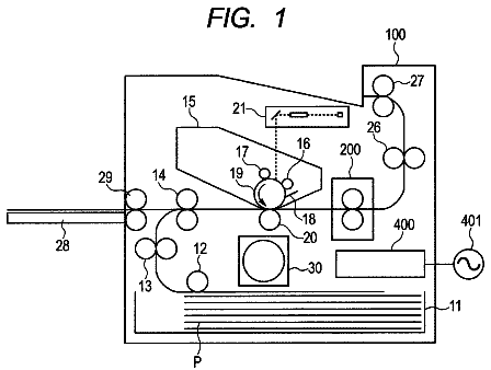
FIG. 1 is an illustrative cross-sectional view illustrating a configuration of an image forming apparatus on which a process cartridge including a developing apparatus equipped with a developer container according to an exemplary embodiment of the present invention is detachably mounted.
FIG. 2 is an illustrative cross-sectional view illustrating a configuration of a first exemplary embodiment of the process cartridge including the developing apparatus equipped with the developer container according to the exemplary embodiment of the present invention and the image forming apparatus on which this process cartridge is to be mounted.
FIGS. 3A, 3B, and 3C are partial cross-sectional views illustrating how a conveyance member of the developer container according to the first exemplary embodiment is vibrated to thereby convey developer.
FIG. 4 is an illustrative cross-sectional view illustrating a configuration of a second exemplary embodiment of the process cartridge including the developing apparatus equipped with the developer container according to an exemplary embodiment of the present invention.
FIG. 5 is an illustrative cross-sectional view illustrating a configuration of a third exemplary embodiment of the process cartridge including the developing apparatus equipped with the developer container according to an exemplary embodiment of the present invention, and the image forming apparatus on which this process cartridge is to be mounted.
FIGS. 6A, 6B, and 6C are partial cross-sectional views illustrating how the conveyance member of the developer container according to the third exemplary embodiment is vibrated to thereby convey the developer.
Description of the embodiments
One exemplary embodiment of an image forming apparatus on which a process cartridge including a developing apparatus equipped with a developer container according to each of exemplary embodiments of the present invention is detachably mounted will be specifically described with reference to the drawings. However, the present invention does not necessarily have to be limited to dimensions, materials, shapes, a relative layout, and the like of component parts that will be described in each of the following exemplary embodiments. Further, in the following description, a longitudinal direction of the process cartridge is an axial direction of an image bearing member. Further, a left and a right respectively mean a left and a right, in a direction in which the recording medium is conveyed, when a recording medium is viewed from above. Further, an upper surface and a lower surface of the process cartridge mean a surface located on an upper side and a surface located on a lower side with the process cartridge mounted on a main body of the image forming apparatus, respectively.
FIGS. 1 to 3 relate to a first exemplary embodiment of the image forming apparatus on which the process cartridge including the developing apparatus equipped with the developer container according to one of the exemplary embodiments of the present invention is detachably mounted. First, a configuration of this first exemplary embodiment will be described with reference to FIGS. 1 to 3 .
<Image Forming Apparatus>
An overall configuration of an electrophotographic image forming apparatus 100 will be described now with reference to FIG. 1 . FIG. 1 is an illustrative cross-sectional view illustrating a configuration of the image forming apparatus 100 on which a process cartridge B (process cartridge) according to the first exemplary embodiment is mounted. The image forming apparatus 100 according to the present exemplary embodiment is an example in which the present invention is applied to a laser beam printer.
As illustrated in FIG. 1 , the image forming apparatus 100 includes the process cartridge B detachably mounted on a main body of this image forming apparatus 100 . A photosensitive drum 7 , which serves as an image bearing member, is disposed in the process cartridge B.
Further, the image forming apparatus 100 emits, from a laser scanner which serves as an image exposure unit, laser light 1 a based on image information onto a surface of the photosensitive drum 7 evenly charged by a charging roller 8 illustrated in FIG. 2 , which serves as a charging unit, to scan and expose this surface with and to the laser light 1 a . As a result, an electrostatic latent image is formed on the surface of the photosensitive drum 7 .
After that, application of a developing bias voltage to the developing roller 10 d illustrated in FIG. 2 , which serves as the developer bearing member, causes toner borne on a surface of this developing roller 10 d , which is used as developer, to be supplied to the electrostatic latent image formed on the surface of the photosensitive drum 7 to develop the electrostatic latent image, thereby forming a toner image.
On the other hand, recording media 2 are fed from a sheet cassette 3 a illustrated in FIG. 1 by a pickup roller 3 b in synchronization with the operation of forming the toner image onto the surface of the photosensitive drum 7 . Examples usable as the recording medium 2 include paper, an overhead transparency (OHT) sheet used together with an overhead projector (OHP) and made of a transparent sheet, and a fabric. Then, the recording media 2 are separated and fed one by one by collaboration between the pickup roller 3 b and a separation member 3 c disposed in pressure contact with this pickup roller 3 b.
After being separated and fed one by one by the collaboration between the pickup roller 3 b and the separation member 3 c , the recording media 2 are sequentially conveyed by conveyance rollers 20 and 21 , and a leading edge of each of the recording media 2 runs into a registration roller 22 that is temporarily static. Then, firmness of a material of this recording medium 2 allows the leading edge of this recording medium 2 to be brought into abutment along a nip portion of the registration rollers 22 , which contributes to a correction of a skew.
After that, the recording medium 2 is conveyed while being sandwiched by the registration rollers 22 in such a manner that a position thereof matches the toner image formed on the surface of the photosensitive drum 7 . Then, this recording medium 2 is conveyed along a conveyance guide 3 f 1 to a transfer nip portion T, where the photosensitive drum 7 disposed in the process cartridge B and a transfer roller 4 serving as a transfer unit are located opposite from each other.
Then, a transfer bias voltage is applied to the transfer roller 4 , by which the toner image formed on the surface of the photosensitive drum 7 is transferred onto the recording medium 2 conveyed to the transfer nip portion T. The recording medium 2 with the toner image transferred thereon is conveyed along a conveyance guide 3 f 2 to a fixing device 5 , which serves as a fixing unit.
The fixing device 5 includes a driving roller 5 a , and a fixing rotational member 5 d constructed with use of a cylindrical sheet containing a heater 5 b therein and rotatably supported by a support member 5 c . Then, the fixing device 5 applies heat and a pressure onto the recording medium 2 passing through a fixing nip portion between the fixing rotational member 5 d and the driving roller 5 a , by which the toner image is fixed onto this recording medium 2 by being heated.
The recording medium 2 with the toner image fixed thereon by being heated by the fixing device 5 is conveyed to a discharge roller 3 d by a conveyance roller 23 . The discharge roller 3 d discharges the recording medium 2 with the toner image fixed thereon to a discharge unit 6 . The image forming apparatus 100 forms an image onto the recording medium 2 with use of the developer (the toner) in this manner.
A controller 50 illustrated in FIG. 1 , which serves as a control unit, controls driving of various kinds of devices disposed within the main body of the image forming apparatus 100 . The controller 50 according to the present exemplary embodiment controls driving of a vibration providing member 13 , which will be described in detail below.
<Process Cartridge>
Next, a configuration of the process cartridge B will be described with reference to FIG. 2 . FIG. 2 is an illustrative cross-sectional view illustrating the configuration of the process cartridge B. As illustrated in FIG. 2 , the process cartridge B according to the present exemplary embodiment includes the photosensitive drum 7 as the image bearing member that bears the toner image (a developer image), and at least one image forming process unit.
The at least one image forming process units includes the charging roller 8 , which serves as the charging unit that charges the surface of the photosensitive drum 7 , and the developing unit 10 , which serves as the developing unit that develops the electrostatic latent image formed on the surface of the photosensitive drum 7 . Further, the at least one image forming process units include, for example, a cleaning blade 11 a , which serves as a cleaning unit that cleans the surface of the photosensitive drum 7 by removing the tonner remaining on the surface of the photosensitive drum 7 after the toner image is transferred therefrom.
A drum unit 11 illustrated in FIG. 2 includes a drum frame 11 d , which rotatably supports the photosensitive drum 7 . Further, the cleaning blade 11 a is disposed in the drum frame 11 d . Further, the charging roller 8 is rotatably disposed in the drum frame 11 d . Further, a removed toner storage unit 11 c and a gathering sheet 11 b are provided in the drum frame 11 d.
The developing unit 10 includes a developing frame 10 f 1 , which rotatably supports the developing roller 10 d . A developing chamber 10 i is formed in the developing frame 10 f 1 .
A developer container 14 , which contains the toner to be used as the developer, includes a frame member 14 a , and a developer conveyance plate 14 b , which serves as a plate-shaped conveyance member on a surface of which the toner to be used as the developer is placed and conveyed. The frame member 14 a and the developer conveyance plate 14 b form an outer shell of the developer container 14 . Further, the developer conveyance plate 14 b , which serves as the conveyance member, includes a vibration target unit 14 b 1 , which receives driving (a vibration) for conveying the toner to be used as the developer and then transmits the driving (the vibration) to this developer conveyance plate 14 b . The vibration target unit 14 b 1 is located below the developer conveyance plate 14 b.
The developer container 14 further includes an opening member 14 c , which has an opening 19 for discharging the toner to be used as the developer from this developer container 14 . Further, the developer container 14 includes a flexible coupling member 14 d , which couples the frame member 14 a , the opening member 14 c , and the developer conveyance plate 14 b with one another. The flexible coupling member 14 d is disposed across an entire circumference of the developer conveyance plate 14 b . The coupling member 14 d extends/compresses, or swings when the developer conveyance plate 14 b serving as the conveyance member conveys the developer toward the opening 19 side (an opening side).
A developer storage unit (a storage unit) 14 t , where the developer is stored, is formed by the developer conveyance plate 14 b serving as the conveyance member, the coupling member 14 d , the opening member 14 c , and the frame member 14 a . As understood from FIG. 2 , the developer conveyance plate 14 b , which serves as the conveyance member, forms a bottom of the developer storage unit 14 t . Therefore, a member for forming the bottom does not need to be prepared additionally. The developer conveyance plate 14 b , which serves as the conveyance member, is disposed on a lower side (a lower end side) where a lower end 19 b of the opening 19 is located. The opening 19 includes an upper end 19 a.
The developer container 14 stores the developer (the toner) in the developer storage unit 14 t . The developer container 14 is connected to the developing unit 10 by the opening member 14 c coupled with the developing unit 10 , and the developing chamber 10 i of the developing unit 10 and the developer storage unit 14 t of the developer container 14 are in communication with each other via the opening 19 of the opening member 14 c . The process cartridge B according to the present exemplary embodiment includes the drum unit 11 , the developing unit 10 , and the developer container 14 .
<Image Forming Process>
Next, an image forming process by the process cartridge B will be described with reference to FIGS. 1 and 2 . Referring to FIG. 2 , first, the photosensitive drum 7 having a photosensitive layer is rotated, and a charging bias voltage is applied to the charging roller 8 serving as the charging unit, by which the surface of the photosensitive drum 7 is evenly charged.
After that, the evenly charged surface of the photosensitive drum 7 is scanned with and exposed to the laser light 1 a based on the image information that is emitted from the laser scanner 1 illustrated in FIG. 1 via an exposure opening 9 b provided at the drum frame 11 d of the process cartridge B. As a result, the electrostatic latent image is formed on the surface of this photosensitive drum 7 .
After that, the developing bias voltage is applied to the developing roller 10 d disposed in the developing unit 10 (the developing apparatus), by which the developer (the toner) borne on the surface of this developing roller 10 d is supplied to the electrostatic latent image formed on the surface of the photosensitive drum 7 . As a result, the electrostatic latent image formed on the surface of the photosensitive drum 7 is developed to be visualized into a visible image as the toner image.
The developing unit 10 rotatably supports the developing roller 10 d as the developer bearing member that bears the developer. In the present exemplary embodiment, as illustrated in FIG. 2 , the developer conveyance plate 14 b serving as the conveyance member, the coupling member 14 d , the opening 19 , and the developing roller 10 d serving as the developer bearing member are arranged in this order from an upstream side to a downstream side in the developer conveyance direction J 1 (from a right side to a left side in FIG. 2 ).
A toner layer provided with a charge from frictional electrification by a developing blade 10 e together with the rotation of the developing roller 10 d is formed on the surface of this developing roller 10 d . The toner borne on the surface of the developing roller 10 d is transferred to the electrostatic latent image on the surface of the photosensitive drum 7 , by which the toner image is formed onto the surface of the photosensitive drum to visualize the electrostatic latent image into the visible image.
After that, the transfer bias voltage, which has an opposite polarity from a polarity of the toner image on the surface of the photosensitive drum 7 , is applied to the transfer roller 4 illustrated in FIG. 1 . By this application, the toner image on the surface of the photosensitive drum 7 is transferred onto the recording medium 2 . The toner remaining on the surface of the photosensitive drum 7 after the toner image is transferred onto the recording medium 2 is swept off by the cleaning blade 11 a serving as the cleaning unit fixed to the drum frame 11 d by a fixation unit 11 h illustrated in FIG. 2 . Further, the toner is gathered up by the gathering sheet 11 b to be collected into the removed toner storage unit 11 c.
<Developer Conveyance Apparatus>
Next, a configuration of a developer conveyance device 200 will be described with reference to FIGS. 2 and 3 . The developer conveyance device 200 includes the developer container 14 . The developer container 14 includes the frame member 14 a , the developer conveyance plate 14 b , the opening member 14 c , and the coupling member 14 d.
The developer conveyance device 200 includes the vibration target unit 14 b 1 . This vibration target unit 14 b 1 is disposed under a lower surface of the developer conveyance plate 14 b in a protruding manner. Acceleration a of a reciprocating motion is provided to this developer conveyance plate 14 b via this vibration target unit 14 b 1 along a developer conveyance direction J 1 illustrated in FIGS. 2 and 3B . Further, the developer conveyance device 200 includes the vibration providing member 13 , in which this vibration target unit 14 b 1 is detachably fitted and which is constructed with use of piezoelectric elements that vibrate this vibration target unit 14 b 1 along the developer conveyance direction J 1 .
Direct-current power sources 44 a and 44 b illustrated in FIGS. 3A to 3C are controlled by the controller 50 , which serves as the control unit. The following voltages are applied to electrodes disposed on respective both ends of a pair of piezoelectric elements 43 a and 43 b , which are configured as the vibration providing member 13 . The controller 50 turns on and off these direct-current power sources 44 a and 44 b at predetermined timings to thereby cause the voltages to be applied to the electrodes. Then, the piezoelectric elements 43 a and 43 b are mechanically deformed according to a frequency of this switching.
This deformation causes the vibration providing member 13 , which is constructed with use of the pair of piezoelectric elements 43 a and 43 b , to vibrate, and this vibration is transmitted to the vibration target unit 14 b 1 to thereby vibrate this vibration target unit 14 b 1 along the developer conveyance direction J 1 . An electrostrictive vibrator or a magnetostrictive vibrator can be used as each of the piezoelectric elements 43 a and 43 b.
As illustrated in FIG. 2 , a reception unit 100 a , on which the process cartridge B is to be mounted, is prepared on the main body side of the image forming apparatus 100 . A recessed portion 100 b , in which the vibration providing member 13 is disposed, is formed at this reception unit 100 a . Support units 17 a and 17 b are erected in the recessed portion 100 b . One ends of the pair of piezoelectric elements 43 a and 43 b are fixed to both sides of a holder unit 12 , and the other ends of the pair of piezoelectric elements 43 a and 43 b are fixed to these support units 17 a and 17 b , respectively.
When the process cartridge B illustrated in FIG. 2 is mounted on the reception unit 100 a prepared at the main body of the image forming apparatus 100 , the developer conveyance device 200 is positioned in the following manner. As illustrated in FIGS. 3A to 3C , the vibration target unit 14 b 1 , which is disposed under the lower surface of the developer conveyance plate 14 b in the protruding manner, is fitted in a recessed portion 12 a of the holder unit 12 .
In the present exemplary embodiment, the developer conveyance device 200 is configured to vibrate the vibration target unit 14 b 1 using the pair of piezoelectric elements 43 a and 43 b , which is disposed, via the holder unit 12 , on both sides of this vibration target unit 14 b 1 protruding under the lower surface of the developer conveyance plate 14 b , along the developer conveyance direction J 1 illustrated in FIG. 2 .
As illustrated in FIGS. 3A to 3C , the vibration target unit 14 b 1 , which protrudes under the lower surface of the developer conveyance plate 14 b , is set up in the following manner. The vibration target unit 14 b 1 is fitted in the recessed portion 12 a of the holder unit 12 , which is disposed at the vibration providing member 13 mounted on the main body side of the image forming apparatus 100 so as to be reciprocatable in the developer conveyance direction J 1 illustrated in FIG. 3B and the developer conveyance opposite direction J 2 illustrated in FIG. 3C .
The individual direct-current power sources 44 a and 44 b are electrically connected to the electrodes disposed on the both end surfaces of the individual piezoelectric elements 43 a and 43 b , respectively. Then, the direct-current voltages are applied from the individual direct-current power sources 44 a and 44 b to the both end surfaces of the individual piezoelectric elements 43 a and 43 b , respectively, while being turned on/off at the predetermined timings by the controller 50 illustrated in FIG. 1 , which serves as the control unit.
A direction in which the developer (the toner) placed on the developer conveyance plate 14 b is conveyed is the developer conveyance direction J 1 from the developer storage unit 14 t toward the developing chamber 10 i illustrated in FIG. 2 (the direction from the right side to the left side in FIG. 2 ).
The opening 19 , which is used to supply the developer (the toner) stored in the developer storage unit 14 t of the developer container 14 to the developing roller 10 d in the developer conveyance direction J 1 illustrated in FIG. 2 , is formed at the opening member 14 c.
As illustrated in FIG. 1 , the image forming apparatus 100 is set in such a manner that the developer conveyance plate 14 b , which forms the bottom surface of the developer container 14 , is substantially horizontally arranged with the process cartridge B mounted on the main body of the image forming apparatus 100 .
<Conveyance Member>
Next, a configuration of the developer conveyance plate 14 b , which serves as the plate-shaped conveyance member, will be described. The developer conveyance plate 14 b is the plate-shaped member disposed below the developer (the toner) and used to convey the developer (the toner). The developer conveyance plate 14 b forms the bottom surface of the developer container 14 . Further, the vibration target unit 14 b 1 , to which the vibration of the vibration providing member 13 is transmitted, is disposed under the lower surface of the developer conveyance plate 14 b in the protruding manner. A polystyrene (PS) having a thickness of approximately 1.5 mm is used as a material of the developer conveyance plate 14 b according to the present exemplary embodiment.
<Coupling Member>
Further, as illustrated in FIG. 2 , the developer conveyance plate 14 b is connected swingably in a direction along the developer conveyance direction J 1 and the developer conveyance opposite direction J 2 by the frame member 14 a , the opening member 14 c , and the flexible coupling member 14 d of the developer container 14 . A flexible silicon rubber having a thickness of approximately 300 μm is used as a material of the coupling member 14 d according to the present exemplary embodiment.
<Function of Conveying Developer>
Next, a function of conveying the developer by the developer conveyance device 200 will be described. In the present exemplary embodiment, the vibration providing member 13 , which is constructed with use of the pair of piezoelectric elements 43 a and 43 b , is disposed on the main body side of the image forming apparatus 100 . As illustrated in FIGS. 2 and 3A to 3C , the state in which the process cartridge B is mounted on the main body of the image forming apparatus 100 is described as follows. The vibration target unit 14 b 1 , which protrudes under the lower surface of the developer conveyance plate 14 b disposed in the process cartridge B, is fitted in the recessed portion 12 a of the holder unit 12 of the vibration providing member 13 disposed on the main body of the image forming apparatus 100 .
Then, the direct-current power sources 44 a and 44 b are controlled by the controller 50 . The direct-current voltages are applied from these direct-current power sources 44 a and 44 b to the electrodes disposed on the both ends of the piezoelectric elements 43 a and 43 b , which are used to construct the vibration providing member 13 , at the predetermined timings. This application causes the vibration providing member 13 , which is constructed with use of the pair of piezoelectric elements 43 a and 43 b , to vibrate at a predetermined frequency, and this vibration of the vibration providing member 13 is transmitted to the developer conveyance plate 14 b via the vibration target unit 14 b 1 .
As a result, the accelerations a 1 and a 2 of the reciprocating motion are provided to the developer conveyance plate 14 b along the developer conveyance direction J 1 illustrated in FIGS. 2 and 3B and the developer conveyance opposite direction J 2 illustrated in FIG. 3C , respectively. Then, this developer conveyance plate 14 b is vibrated along the developer conveyance direction J 1 and the developer conveyance opposite direction J 2 .
The process cartridge B is mounted according to an operation of attaching and detaching the process cartridge B to and from the main body of the image forming apparatus 100 in the following manner. The process cartridge B is attached to the recessed portion 12 a of the holder unit 12 of the vibration providing member 13 disposed on the main body of this image forming apparatus 100 in the following manner. The vibration target unit 14 b 1 , which protrudes under the lower surface of the developer conveyance plate 14 b disposed in the process cartridge B, is detachably and separably fitted in the recessed portion 12 a.
In the developer conveyance device 200 according to the present exemplary embodiment, the developing frame 10 f 1 of the developing unit 10 and the developer container 14 are integrally coupled with each other via the opening member 14 c . Then, the developer conveyance plate 14 b , which forms the bottom surface of the developer container 14 , and the flexible coupling member 14 d are vibrated by the vibration providing member 13 via the vibration target unit 14 b 1 disposed under this developer conveyance plate 14 b . This configuration can improve a volume in the developer storage unit 14 t , compared to the configuration including the member for conveying the developer (the toner) inside the developer container, such as Japanese Patent Application Laid-Open No. 2002-196585. Further, this configuration can reduce a space necessary for the swinging motion, compared to the configuration that elastically deforms an arm to thereby swing a reception plate, such as Japanese Patent Application Laid-Open No. 59-227618.
<Behavior of Developer During Vibration>
Next, a behavior of the developer (the toner) on the surface of the developer conveyance plate 14 b will be described. First, an operation of the developer conveyance device 200 will be described with reference to FIGS. 3A to 3C . A distal end 14 b 2 of the developer conveyance plate 14 b , which is illustrated in FIG. 2 , reciprocates between the following positions by the vibration of the vibration providing member 13 via the vibration target unit 14 b 1 .
The vibration target unit 14 b 1 protruding under the lower surface of the developer conveyance plate 14 b , which is illustrated in FIG. 3A , is fitted and attached in the recessed portion 12 a of the holder unit 12 of the vibration providing member 13 kept in a static state. At this time, the coupling member 14 d is in a natural state without extending/compressing or swinging. The distal end 14 b 2 of the developer conveyance plate 14 b reciprocates from an initial position 14 b 2 B at this time to the following positions.
The distal end 14 b 2 of the developer conveyance plate 14 b , which is illustrated in FIG. 2 , is displaced to a position 14 b 2 A, where the distal end 14 b 2 is maximally displaced in the developer conveyance direction J 1 illustrated in FIG. 3B , by the vibration of the vibration providing member 13 via the vibration target unit 14 b 1 . At this time, the coupling member 14 d is in a compressed state. Further, the distal end 14 b 2 of the developer conveyance plate 14 b is displaced to a position 14 b 2 C, where the distal end 14 b 2 is maximally displaced in the developer conveyance opposite direction J 2 illustrated in FIG. 3C , which is the opposite direction from the developer conveyance direction J 1 . At this time, the coupling member 14 d is in an extended state. The developer conveyance plate 14 b is configured reciprocatably between these positions. The coupling member 14 d swings according to the reciprocating displacement of the developer conveyance plate 14 b , which is illustrated in FIGS. 3A to 3C .
<Setting of Acceleration>
The maximum acceleration a 1 (max) in the developer conveyance direction J 1 illustrated in FIG. 3B , which is provided from the vibration target unit 14 b 1 with the vibration of the vibration providing member 13 transmitted thereto to the developer conveyance plate 14 b , is set in the following manner. The maximum acceleration a 1 (max) is set to a lower acceleration than the maximum acceleration a 2 (max) in the developer conveyance opposite direction J 2 illustrated in FIG. 3C as the opposite direction from the developer conveyance direction J 1 , which is provided from this vibration target unit 14 b 1 to the developer conveyance plate 14 b.
The maximum acceleration a 2 (max) of the developer conveyance plate 14 b vibrated by the vibration providing member 13 in the developer conveyance opposite direction J 2 illustrated in FIG. 3C is set in the following manner. The maximum acceleration a 2 (max) is set to a maximum acceleration a (max) high enough to allow the developer (the toner) on the surface of this developer conveyance plate 14 b to slide on the surface of this developer conveyance plate 14 b.
The pair of piezoelectric elements 43 a and 43 b , which is used to construct the vibration providing member according to the present exemplary embodiment, is subject to the application of the direct-current voltages to the electrodes disposed on the respective both ends thereof at the predetermined timings. This application causes the pair of piezoelectric elements 43 a and 43 b to extend. The pair of piezoelectric elements 43 a and 43 b is made of elastic members (piezoelectric elements) that compress into their respective original sizes by a stop of the application of these direct-current voltages. A waveform of the voltage applied to each of the piezoelectric elements 43 a and 43 b , and the switching frequency therefor are appropriately controlled. This control can generate an acceleration difference (a 1 <a 2 ) between the acceleration a 1 , at which the developer conveyance plate 14 b is displaced in the developer conveyance direction J 1 (a forward path), and the acceleration a 2 , at which the developer conveyance plate 14 b is displaced in the developer conveyance opposite direction J 2 (a backward path).
For example, suppose that the direct-current voltage to be applied to each of the piezoelectric elements 43 a and 43 b is set to approximately 500 V, and is set to have a square waveform at a frequency of approximately 60 Hz as a voltage waveform thereof. The direct-current voltage to be applied from the direct-current power source 44 a to the piezoelectric element 43 a is set to a higher voltage than the direct-current voltage to be applied from the direct-current power source 44 b to the piezoelectric element 43 b . This setting can generate the acceleration difference (a 1 <a 2 ) between the acceleration a 1 , at which the developer conveyance plate 14 b is displaced in the developer conveyance direction J 1 , and the acceleration a 2 , at which the developer conveyance plate 14 b is displaced in the developer conveyance opposite direction J 2 .
This setting causes the developer (the toner) on the developer conveyance plate 14 b to slide on the surface of this developer conveyance plate 14 b due to its own inertia when this developer conveyance plate 14 b is displaced in the developer conveyance opposite direction J 2 illustrated in FIG. 3C . This means that the developer (the toner) on the developer conveyance plate 14 b is relatively displaced on this developer conveyance plate 14 b to the left side in FIG. 3C from the point of view of this developer conveyance plate 14 b.
On the other hand, the maximum acceleration a 1 (max), in the developer conveyance direction J 1 , of the developer conveyance plate 14 b vibrated by the vibration providing member 13 via the vibration target unit 14 b 1 illustrated in FIG. 3B is set in the following manner. The maximum acceleration a 1 (max) is set to a lower acceleration than the maximum acceleration a 2 (max) in the developer conveyance opposite direction J 2 illustrated in FIG. 3C . In this case, the developer (the toner) on this developer conveyance plate 14 b is displaced integrally with this developer conveyance plate 14 b without sliding on the surface of this developer conveyance plate 14 b.
Repetition of such vibrations causes the developer (the toner) on this developer conveyance plate 14 b to be conveyed on the surface of this developer conveyance plate 14 b in the developer conveyance direction J 1 illustrated in FIG. 3B .
<Condition for Sliding Motion of Developer>
The developer (the toner) on the surface of the developer conveyance plate 14 b slides on the surface of this developer conveyance plate 14 b when a certain condition is satisfied. Next, this condition will be described. The developer (the toner) on the surface of the developer conveyance plate 14 b slides on the surface of this developer conveyance plate 14 b under the following condition. Assume that μ0 represents a static friction coefficient between the surface of this developer conveyance plate 14 b and the developer (the toner), g represents a gravitational acceleration, and {μ0×g} is a product of these static friction coefficient μ0 and gravitational acceleration g.
Then, the vibration providing member 13 is vibrated with the developer (the toner) placed on the surface of the developer conveyance plate 14 b . The acceleration a 1 , at which this developer conveyance plate 14 b is driven to reciprocate along the developer conveyance direction J 1 illustrated in FIG. 3B by the vibration of the vibration providing member 13 via the vibration target unit 14 b 1 , is set so as to be higher than {μ0×g}. Alternatively, the acceleration a 2 , at which the developer conveyance plate 14 b is driven to reciprocate along the developer conveyance opposite direction J 2 illustrated in FIG. 3C , is set so as to be higher than the product {ρ0×g}. This setting causes the developer (the toner) on the surface of the developer conveyance plate 14 b to slide on the surface of this developer conveyance plate 14 b.
<Capability to Convey Developer>
Next, consideration is to be made on the maximum acceleration a 1 (max), at which this developer conveyance plate 14 b is displaced by the vibration of the vibration providing member 13 in the developer conveyance direction J 1 illustrated in FIG. 3B . Further, consideration is to be made on the maximum acceleration a 2 (max), at which this developer conveyance plate 14 b is displaced by the vibration of the vibration providing member 13 in the developer conveyance opposite direction J 2 illustrated in FIG. 3C . Further, consideration is to be made on {μ0×g}, which is the product of the static friction coefficient ρ0 between the surface of the developer conveyance plate 14 b and the developer (the toner) and the gravitational acceleration g. A relationship among them, and a capability to convey the developer (the toner) on the surface of this developer conveyance plate 14 b will be described now.
<Acceleration Condition Capable of Causing Conveyance of Developer>
Consideration is to be made on the maximum acceleration a 1 (max), at which this developer conveyance plate 14 b is displaced by the vibration of the vibration providing member 13 in the developer conveyance direction J 1 illustrated in FIG. 3B . Further, consideration is to be made on the maximum acceleration a 2 (max), at which the developer conveyance plate 14 b is displaced in the developer conveyance opposite direction J 2 illustrated in FIG. 3C . Then, the maximum acceleration a 1 (max) and the maximum acceleration a 2 (max) are in the following relationship with each other. The relationship between the maximum acceleration a 1 (max) and the maximum acceleration a 2 (max) may be expressed by the following expression, an expression 1, with use of the product {μ0×g} of the static friction coefficient μ0 between the surface of the developer conveyance plate 14 b and the developer (the toner), and the gravitational acceleration g. {μ0× g}<a 1(max)< a 2(max) [Expression 1]
The description continues in the full USPTO document.
 Lapsed, fee not paid1 drawing