 Lapsed, fee not paid5 drawings
Industrial Equipment · US 9,772,057 B2
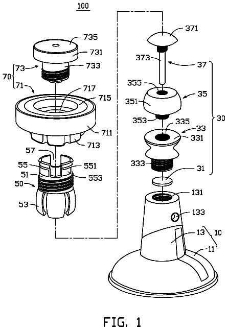
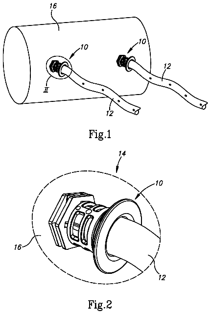
Irrigation pipe coupler
An irrigation pipe coupler can engage an open end of an irrigation pipe with its forward end.
US 9,772,061 B2 · Inventors: Farkas; Pal
Sheet 1 of 9 from the published document. All sheets in the USPTO PDF
The invention relates to an examination process for replicating hydrate forming conditions in a gas pipeline and monitoring the effect of a low dosage hydrate inhibitor (LDHI) in suppressing hydrate formation at temperatures encountered in gas pipelines for dynamically determining LDHI feed rate for inhibition of hydrate formation comprising the steps of: diverting from a gas well a sample gas stream at a preselected rate; introducing the diverted gas stream into a gas conduit through an inlet of the gas conduit; feeding LDHI into the diverted gas stream at one or more predetermined rates to produce a LDHI-containing gas stream; introducing the LDHI-containing gas stream into a coolable portion of the gas conduit, which coolable portion is provided with pressure sensors along the coolable portion; cooling the LDHI-containing gas stream passing through the coolable portion of the gas conduit to a predetermined temperature; and monitoring pressure of the LDHI-containing gas stream passing through the coolable portion of the gas conduit for a predetermined time range being at least as long as the gas residence time within the gas pipeline; whereby a substantially uniform pressure drop along the coolable portion of the gas conduit during the predetermined time range indicates a LDHI feed rate sufficient to suppress hydrate formation at the predetermined temperature.
When transporting natural gas in a pipeline hydrates may form in the gas as the temperature of the gas decreases. During hydrate formation crystals are formed which can grow and agglomerate thereby forming hydrate plugs in the gas pipeline which hinder the gas transport thereafter. This problem is generally overcome on the one hand by heating the pipeline and on the other hand by feeding anti-hydrate compounds, typically thermodynamic inhibitors such as methanol, glycol or so called LDHI (Low Dosage Hydrate Inhibitor) type of inhibitors, into the pipeline that inhibit hydrate formation. The disadvantage of heating the pipeline is that it increases the cost of the transport of natural gas substantially. The use of methanol and other type of thermodynamic inhibitors is declining as these are strongly contaminating the environment, and require a substantially higher concentration than the L
8 of 9 drawing sheets so far from the published document, cropped to the drawing. Every sheet is in the USPTO PDF.
What the patent claimed, word for word. All of it is now free to use.
The invention relates to an examination process for the in situ determination of rate of feeding an inhibitor into a gas pipeline for preventing hydrate formation.
When transporting natural gas in a pipeline hydrates may form in the gas as the temperature of the gas decreases. During hydrate formation crystals are formed which can grow and agglomerate thereby forming hydrate plugs in the gas pipeline which hinder the gas transport thereafter. This problem is generally overcome on the one hand by heating the pipeline and on the other hand by feeding anti-hydrate compounds, typically thermodynamic inhibitors such as methanol, glycol or so called LDHI (Low Dosage Hydrate Inhibitor) type of inhibitors, into the pipeline that inhibit hydrate formation. The disadvantage of heating the pipeline is that it increases the cost of the transport of natural gas substantially. The use of methanol and other type of thermodynamic inhibitors is declining as these are strongly contaminating the environment, and require a substantially higher concentration than the LDHI type of inhibitors. Two types of LDHIs are known: the kinetic inhibitors, which decrease the speed of hydrate formation, and the anti-agglomerate inhibitors, which prevent agglomeration of the hydrate particles. In at least 95% of the cases the companies still employ the conventional, environmentally unfriendly methanol or glycol and expensive heating in order to protect gas pipes from hydrate plugs. Application of the environmentally friendly inhibitors is not yet wide-spread due to the higher expenses, although strong ecological interest is tied to it. The novelty of the present complex invention, in its details and as a whole, ensures the cost efficient and safe employment of inhibitors.
Hereinafter the LDHI type of inhibitors will be discussed, which will simply be referred to as LDHI or inhibitor for the sake of simplicity.
Inhibitors of different type and composition are available of which the selection of the most suitable inhibitor and its feeding rate depends on the various parameters of the gas well, the gas pipeline and the gas to be transported. Such parameters are for example the depth of the gas well, its yield, the natural gas condensate content, the stratum water content, and the carbon-dioxide content of the natural gas, the length and material quality of the pipeline, the flow parameters, the expected temperature conditions within the pipeline, etc. The suitable inhibitor is generally chosen by taking a sample from the gas well-head, transporting the sample to a remote laboratory where different inhibitors are added to the sample and measurements are performed in order to determine the efficiency of the inhibitor. The disadvantage of this method is that the composition of the gas sample and the ratio of the gas phase and liquid phase may change during transportation due to chemical reactions taking place inside the sample. A further disadvantage is that the amount of the sample does not allow for investigating hydrate formation at an industrial scale which may substantially influence the usability of the measurement results.
A great disadvantage of the currently employed inhibitor feeding systems is that regular on-site inspection is required for the continuous control of the reliability of operation. Furthermore, the feeding quantity can only be set on-site as well. In case of possible breakdown of operation or of a change of the environmental conditions (for example temperature) this system can only respond with big delay.
Presently, there is no known, complex, inhibitor feeding system and process using on-site measurements with the help of which the feeding of the rather expensive inhibitor into a gas pipeline could be optimized efficiently. The present solutions do not allow for determining the minimal quantity of inhibitor to be fed in, nor does it allow for early detection of a possible malfunction or breakdown of the feeding system.
It is an objective of the present invention to provide a process which overcomes the problems associated with the prior art. In particular, it is an objective of the invention to provide a process, which allows for the in situ determination of the rate of feeding an inhibitor into a gas pipeline for preventing hydrate formation, as well as remote control of the process of inhibitor feeding, thereby contributing to the spreading of the hydrate prevention technology that is based on the use of inhibitors.
The present invention comprises an examination process for replicating hydrate forming conditions in a gas pipeline and monitoring the effect of a low dosage hydrate inhibitor (LDHI) in suppressing hydrate formation at temperatures encountered in gas pipelines for dynamically determining LDHI feed rate for inhibition of hydrate formation. The process comprises the steps of: diverting from a gas well a sample gas stream at a preselected rate; introducing the diverted gas stream into a gas conduit through an inlet of the gas conduit; feeding LDHI into the diverted gas stream at one or more predetermined rates to produce a LDHI-containing gas stream; introducing the LDHI-containing gas stream into a coolable portion of the gas conduit, which coolable portion is provided with pressure sensors along the coolable portion; cooling the LDHI-containing gas stream passing through the coolable portion of the gas conduit to a predetermined temperature; and monitoring pressure of the LDHI-containing gas stream passing through the coolable portion of the gas conduit for a predetermined time period;
whereby a substantially uniform pressure drop along the coolable portion of the gas conduit during the predetermined time period (observation time) indicates a LDHI feed rate sufficient to suppress hydrate formation at the predetermined temperature.
Preferably the preferred predetermined temperature to which the coolable portion is cooled is a temperature below hydrate formation temperature at gas pressures existing in a gas pipeline. The predetermined temperature is preferably between about 0° C. to about 16° C.
Gas observation time within the examined gas pipeline usually is in the range of about 1000 seconds to about 10000 seconds. Preferably, the predetermined observation time is at least twice the gas Residence Time within the coolable portion of the gas conduit. As used herein and in the appended claims, the term “Residence Time” means the time a particular gas molecule is within the coolable portion of the gas conduit and is calculated by a formula Residence Time equals volume of coolable portion of gas conduit divided by volumetric flow rate through the coolable portion of the gas conduit.
Preferably the process further includes the steps of providing an LDHI feeder comprising a telemetric data transmission system for the remote control and monitoring of the LDHI feeder; connecting the LDHI feeder to a feeding point of the gas pipeline; determining a temperature of the examined gas pipeline; and feeding the LDHI into the gas pipeline through the feeding point by the LDHI feeder at a LDHI feed rate sufficient to suppress hydrate formation at a temperature not exceeding the gas pipeline temperature. The gas pipeline temperature may be determined for example along the gas pipeline in the vicinity of the feeding point.
Certain advantageous embodiments of the invention are defined in the attached dependent claims.
FIG. 1 is a schematic diagram of a preferred embodiment of an industrial scale measuring system for preforming the process according to the invention.
FIG. 2 a is a pressure difference diagram obtained in a measurement performed by the measuring system according to FIG. 1 .
FIG. 2 b is a temperature diagram obtained in a measurement performed by the measuring system according to FIG. 1 .
FIG. 2 c is a volume flow rate diagram obtained in a measurement performed by the measuring system according to FIG. 1 .
FIG. 3 is a schematic diagram of a preferred embodiment of a laboratory scale measuring system for performing the process according to the invention.
FIG. 4 is a schematic diagram of an alternative laboratory scale measuring system.
FIG. 5 a is a pressure difference diagram obtained in a measurement performed by the measuring system according to FIG. 4 .
FIG. 5 b is a temperature diagram obtained in a measurement performed by the measuring system according to FIG. 4 .
FIG. 5 c is a volume flow rate diagram obtained in a measurement performed by the measuring system according to FIG. 4 .
FIG. 6 is a schematic diagram of an inhibitor feeding system provided with telemetric data transmission for performing the process according to the invention.
FIG. 7 is a schematic block diagram of a telemetric data transmission system of the inhibitor feeding system according to FIG. 6 .
A preferred embodiment of an industrial scale measuring system 200 of an examination system 100 for performing the process according to the invention can be seen in FIG. 1 . The examination system 100 may advantageously comprise a laboratory scale measuring system 300 as well (see FIG. 3 ). The main difference between the industrial scale measuring system 200 and the laboratory scale measuring system 300 is that the gas conduit 10 of the industrial scale measuring system 200 can be connected directly to the well-head of the gas well supplying the gas (natural gas) that is to be examined, whereby the examination may be performed in situ, i.e. on-site at the gas well. Furthermore, the dimensions of the industrial scale measuring system 200 are sufficiently close to the dimensions of the gas pipeline that is used to transport the gas from the gas well, in order to ensure that hydrodynamic and thermodynamic differences do not substantially influence the hydrate formation in the presence of the examined inhibitor.
In contradistinction, the purpose of the optional laboratory scale measuring system 300 is to allow pre-measurements on substantially smaller amounts of gas in order to reduce the number of inhibitors that are to be examined, it is thereby possible to pre-screen in a fast and cost-efficient way which one or more inhibitors should be examined in the industrial scale measuring system 200 .
The industrial scale measuring system 200 comprises a gas conduit 10 having a gas inlet 10 ′ which can be connected to a gas well-head. In the context of the invention the term gas well is understood to include any apparatus, formation or location serving as a gas source, for example a reservoir such as an underground reserve cave or artificial tank, and the term well-head is understood to refer to the gas outlet of such gas sources. The examination system 100 can be used in connection with any gas pipeline (either field conduit or pipes of a facility) or technology pipe in which hydrate formation may occur. Gas can be extracted from such gas pipelines as well, in this case the point of extraction (typically a conduit branch) is regarded as the gas well-head. The gas pipeline is connected to the gas well-head for transporting the gas to a gas collection station or any other place of designation. The purpose of the invention is to determine the required rate of feeding a suitable hydrate inhibitor into such a gas pipeline. The gas transported through the gas pipeline remains inside the gas pipeline (between the input and output locations) for a given residence time, thus the inhibitor and its feed-rate is generally considered adequate if it prevents hydrate formation during this residence time, preferably during twice the residence time.
The gas inlet 10 ′ of the gas conduit 10 is connectable to the well-head, preferably to the gate valve of the blind flange of the well-head assembly (Christmas-tree) or to an upper sample outlet of a conduit branch mounted on the gate valve in order to obtain dry gas free of liquid phase from the highest point of the gate valve. The gas inlet 10 ′ of the gas conduit 10 can be connected to the well-head either directly or indirectly (for example through an accessory part that is not part of the examination system 100 ). In the context of the present invention the gas inlet 10 ′ of the gas conduit 10 is regarded as being connectable to the gas well-head even if it is connectable indirectly, however, after connection continuous gas flow can be ensured from the gas well into the gas conduit 10 .
The gas conduit 10 is preferably formed as a pulse line.
The industrial scale measuring system 200 comprises a heat exchanger 12 and the gas conduit 10 comprises a coolable portion 11 which is arranged in the heat exchanger 12 . If necessary, the coolable portion 11 may also be heatable as well, thus the term coolable should not be interpreted in a limiting sense.
In the context of the present invention the terms “industrial scale” and “laboratory scale” relating to the measurement systems 200 and 300 , respectively, are used for distinguishing purposes only, and do not imply more restriction than if the measuring systems were called “first” and “second” measuring systems 200 , 300 , respectively. However, it can be said that the dimensions (length, inner diameter) of the coolable portion 11 of the industrial scale measuring system 200 are greater than the dimensions of the corresponding coolable portion 111 (see FIG. 3 ) of the laboratory scale measuring system 300 , preferably its length is at least two times greater, more preferably 5 to 15 times greater. The length of the coolable portion 11 of the industrial scale measuring system 200 , which serves for performing the measurements is preferably at least 100 m, and its inner diameter is at least 7 mm in order to be a sufficiently close approximation of the dimensions of the gas pipeline for rendering the modelling reliable. The dimensions of the coolable portion 111 of the laboratory scale measuring system 300 are smaller than this.
The coolable portion 11 of the industrial scale measuring system 200 is preferably formed as a coil pipe 11 ′ the inner diameter of which is chosen so as to avoid capillary effects, in order to ensure better resemblance of the measuring conditions to the hydrodynamic conditions inside the gas pipeline that is connected to the gas well-head. In order to avoid capillary effects the inner diameter is at least 7 mm, more preferably at least 10 mm. In order to reduce the necessary amount of natural gas for the measurement the inner diameter of the coil pipe 11 ′ is preferably not greater than 20 mm. The length of the coil pipe 11 ′ is preferably at least 100 m in order to ensure sufficient heat exchange surface for cooling purposes, and is preferably not more than 200 m, however, longer coil pipes 11 ′ may be used for the simulation of particularly long gas pipelines.
The material properties of the gas conduit 10 and in particular its coolable portion 11 are chosen in accordance with the material properties of the gas pipeline of the gas well in order to render the hydrodynamic and thermodynamic conditions more similar in this regard as well. Since the material of the gas pipelines used at gas wells is generally carbon steel, accordingly, preferably the gas conduit 10 , in particular the coil pipe 11 ′ that is arranged within a heat exchange space 14 of the heat exchanger 12 , is also made of carbon steel since it is preferred to have the same material properties as that of the gas pipeline in order to ensure that the same hydrodynamic conditions arise along the pipe wall. In case the material of the gas pipeline is acid-proof steel, this is preferably modeled by a coil pipe 11 ′ made of acid-proof steel.
The heat exchanger 12 preferably comprises a heat exchange space 14 wherein the coil pipe 11 ′ of the coolable portion 11 is arranged and which can be filled with a cooling medium. The heat exchanger 12 further comprises a tank 16 for discharging the cooling medium, a heat exchange unit 18 for cooling the cooling medium to a desired temperature and a deep freezer aggregator unit 20 . The aforesaid components of the heat exchanger 12 may be connected to each other for example according to the basic circuit diagram illustrated in FIG. 1 , through ball valves 22 , and a pump 24 circulates the cooling liquid and helps to charge or discharge the heat exchange space 14 and the tank 16 of the heat exchanger 12 . Preferably, the liquid level within the tank 16 can be monitored for example by liquid level sensors and/or through a sight glass 26 shown in FIG. 1 .
The industrial scale measuring system 200 preferably comprises an air heater 28 in connection with the heat exchange space 14 of the heat exchanger 12 for reheating the gas transported in the coil pipe 11 ′ in case of hydrate plug formation therein as will be explained in more detail later on.
Pressure measuring devices 30 are arranged at minimum two locations but preferably at four locations along the coolable portion 11 in order to determine the pressure difference between the consecutive locations. According to the present embodiment the pressure measuring devices 30 comprise a first pressure gauge 30 ′ and three differential pressure gauges 30 a , 30 b , 30 c arranged downstream thereof, and the pressure is measured at the inlet of the coil pipe 11 ′, at ¼ of its length, at half of its length and at its outlet as illustrated in FIG. 1 , whereby pressure difference can be measured at three different positions. In case of hydrate formation the location where the hydrate formation occurs can be deducted from the ensuing pressure difference.
The pressure gauge 30 ′ and the differential pressure gauges 30 a , 30 b , 30 c are preferably in connection with a measurement controlling computer 32 such as to be able to transmit the measurement data to the computer 32 , which evaluates the received data with the help of a measurement controlling program. A data transmission connection between the pressure measuring devices 30 and the computer 32 can be ensured through wired or wireless connection (e.g. WiFi connection) as is known per se. In the context of the present invention the term computer is used in a broad sense including any hardware device that is suitable for collecting and processing data and, based thereon, controlling units of the examination system 300 , for example desk top computer, laptop, tablet, smart phone, microcontroller, etc. The computer 32 preferably comprises one or more input devices (for example keyboard 34 , mouse 36 , etc.), one or more output devices (for example display 38 , printer, etc.) and may comprise interfaces that can serve as both input and output devices (for example touch screen, CD/DVD reader/writer, etc.).
Preferably, thermometers 40 a , 40 b and 40 c are connected to the coolable portion 11 of the gas conduit 10 of the industrial scale measuring system 200 for measuring the temperature of the gas transported within the coil pipe 11 ′ at minimum two locations but preferably at three locations and a forth thermometer 40 ′ is provided for measuring the temperature of the cooling liquid. The thermometers 40 a , 40 b , 40 c and 40 ′ preferably transmit the measurement data to the computer 32 .
The industrial scale measuring system 200 preferably further comprises an inhibitor feeding system 42 which is connected to the gas conduit 10 between the gas inlet 10 ′ and the coolable portion 11 . The inhibitor feeding system 42 comprises an inhibitor tank 44 and a feeding pump 46 , preferably an electric feeding pump connected therewith, which may be connected to the gas conduit 10 for example through ball valve 47 and check valve 48 as illustrated in FIG. 1 . Preferably a pressure gauge 49 is provided between the feeding pump 46 and the ball valve 47 .
The gas (natural gas) transported through the gas pipeline from the gas well comprises liquid phase stratum water and/or natural gas condensate in the amount characteristic of the gas well, the presence of which may influence the hydrate formation and the formation of hydrate plugs. The inventor has recognized that the amount of the stratum water and natural gas condensate that can be measured in the gas pipeline does not necessarily correspond to the proportions present in the gas conduit 10 of the industrial scale measuring system 200 , for which reason it is preferred to separate the liquid phase (and any solid contaminants) from the examined gas by a separator 50 , and feed stratum water and natural gas condensate in the proportions measurable in the transport pipeline into the gas conduit 10 upstream of the coolable portion 11 . The industrial scale measuring system 200 preferably comprises for this purpose a stratum water feeding system 52 and a natural gas condensate feeding system 62 both of which are connected to the gas conduit 10 between the separator 50 and the coolable portion 11 .
The stratum water feeding system 52 comprises a stratum water tank 54 and a feeding pump 56 , preferably a pneumatic feeding pump, connected therewith, which may be connected to the gas conduit 10 for example through a ball valve 57 and check valve 58 as illustrated in FIG. 1 . Preferably a pressure gauge 59 is provided between the feeding pump 56 and the ball valve 57 .
Similarly, the natural gas condensate feeding system 62 comprises a natural gas condensate tank 64 and a feeding pump 66 , preferably a pneumatic feeding pump, connected therewith, which may be connected to the gas conduit 10 for example through a ball valve 67 and check valve 68 as illustrated in FIG. 1 . Preferably a pressure gauge 69 is provided between the feeding pump 66 and the ball valve 67 .
The three feeding systems 42 , 52 , 62 can be formed as a single integrated system.
The separator 50 can be any kind of known device suitable for separating liquid. Preferably, a tank 51 is connected to the separator 50 through a ball valve 70 for collecting the separated liquid and solid contaminants. The gas inlet 10 ′ is preferably separated from the separator 50 by a ball valve 72 .
Similarly, a separator 50 ′ can be applied downstream of the coolable portion 11 of the gas conduit 10 in order to separate the natural gas condensate, stratum water and inhibitor that has been fed into the gas stream. Preferably, a tank 51 ′ is also connected to the separator 50 ′ through a ball valve 70 ′. Preferably, the separator 50 ′ is connected to the portion of the gas conduit 10 exiting the heat exchanger 12 through a ball valve 74 .
If the gas inlet 10 ′ of the gas conduit 10 is connected to the gas well, a pressure regulator 80 is preferably connected to the gas conduit 10 downstream of the separator 50 following the gas inlet 10 ′ because the pressure at the gas well is generally somewhat higher than within the gas pipeline and the pressure regulator 80 serves to reduce the pressure of the transported gas in order to reproduce the pressure conditions within the gas transport pipeline connected to the gas well. It is also possible to connect the gas inlet 10 ′ of the gas conduit 10 to a notch on the gas pipeline in which case the pressure regulator 80 is not required.
According to a preferred embodiment the pressure regulator 80 comprises a pressure reducing valve 82 and pressure gauges 84 and 86 connected upstream and downstream thereof, in order to visually present the entry and exit pressure values. The measurement data of the pressure gauges 84 and 86 can be transmitted to the computer 32 , which may control the pressure reducing valve 82 . The pressure regulator 80 is preferably connected to the coil pipe 11 ′ of the coolable portion 11 through a check valve 88 .
A further pressure regulator 90 may be provided upstream of the gas outlet 10 ″ of the gas conduit 10 for setting the pressure of the gas exiting the gas conduit 10 . According to a preferred embodiment the pressure regulator 90 comprises a pressure reducing valve 92 and pressure gauges 94 and 96 connected upstream and downstream thereof, in order to visually present the entry and exit pressure values. The pressure regulator 90 is preferably connected to the separator 50 ′ through a check valve 98 .
The pressure regulator 90 is preferably followed by a choke valve 102 for setting the flow rate of the gas inside the gas conduit 10 which can be measured by a flowmeter 104 . The flowmeter 104 may transmit measurement data to the computer 32 over a data transmission connection therewith. The pressure regulator 90 , the choke valve 102 and the flowmeter 104 are preferably protected from any solid or liquid contaminants that may eventually pass the separator 50 ′ by a filter 99 .
Preferably a conduit 106 for introducing hot water, a conduit 107 for introducing air and/or a conduit 108 for introducing nitrogen is connected to the gas conduit 10 of the industrial scale measuring system 200 between the gas inlet 10 ′ and the coolable portion 11 through ball valves 105 a , 105 b , 105 c respectively. The hot water conduit 106 is advantageously connected to the local hot water network or it may be connected to the cold water network with the interposition of a water heater. The nitrogen is preferably introduced into the conduit 108 from a nitrogen tank 109 .
The examination system 100 comprising the industrial scale measuring system 200 and optionally the laboratory scale measuring system 300 is preferably formed as a mobile station, whereby it can be transported to the location of the gas well, which is to be examined, and the measurements can be performed there. The examination system 100 is preferably provided in a container, thus the measuring apparatuses and accessories located in the container can be easily installed on the site of the examined well, whereby the measurements for preventing hydrate formation can be performed substantially faster and more efficiently, furthermore, the problems associated with the transport of the gas sample can be eliminated. Further advantage of the local (in situ) measurements is that the different stratum water and natural gas condensate content of the well flow can be easily taken into account by feeding the stratum water and natural gas condensate obtained from the well into the examination system 100 . Since the efficiency of the examinations depend considerably on the number of measurements, hence the in situ performance of a high number of measurements can substantially reduce the time required to analyze a gas well; whereas the conventional measurements performed in laboratories inside remote buildings required months, the same measurements may be performed within a week with the help of the mobile station.
The inner space of the container is preferably monitored with a gas detector (not shown) in order to eliminate the risk of a gas explosion, which detector signals at 10% of LEL (Lower Explosive Limit), turns a ventilation fan on at 20% of LEL, and shuts off the electric system at 30% of LEL.
The energy source of the mobile examination system 100 is preferably a current generator.
The industrial scale measuring system 200 is applied as follows.
According to a first step of the process according to the invention the quantity of the inhibitor that is to be fed into the gas pipeline is determined with the help of the industrial scale measuring system 200 . Before starting the measurements the tank 16 of the heat exchanger 12 is filled with a cooling liquid, for example a 3:1 ratio mixture of glycol to distillated water, through the ball valve 22 .
At the start of the measurement the heat exchange space 14 is filled with the cooling liquid from the tank 16 with the help of the pump 24 . The cooling liquid is continuously circulated in the heat exchange space 14 by the deep freezer aggregator unit 20 which is thereby cooled to the desired temperature. The flow can be monitored through the sight glass 26 .
The natural gas to be examined is obtained from the well, through the conduit branch of the well head, which is then transported through a pulse line to the gas inlet 10 ′ of the gas conduit 10 of the measuring system 200 . The natural gas enters the industrial scale measuring system 200 through the ball valve 72 arranged at the gas inlet 10 ′. The liquid phase (practically stratum water and natural gas condensate) and solid contaminants are separated from the introduced natural gas with the help of the separator 50 .
The required pressure for the measurement is then set by the pressure regulator 80 .
In order to examine the formation of hydrates the conditions within the gas pipeline have to be modeled. This is done by determining the amount of stratum water and natural gas condensate carried in the gas pipeline and a corresponding amount of stratum water and natural gas condensate is fed into the gas conduit 10 after the liquid phase has been separated but upstream of the entrance of the coolable portion 11 . The amounts to be fed into the gas conduit 10 can be determined based on data of prior measurements (possibly conducted by third parties).
The feeding of the inhibitor, stratum water and natural gas condensate is ensured by the feeding systems 42 , 52 , 62 such that the inhibitor, stratum water and natural gas condensate are fed into the gas conduit 10 from the tank 44 , 54 , 64 of each feeding system 42 , 52 , 62 by the electric or pneumatic feeding pumps 46 , 56 , 66 , respectively. The feed rate of the inhibitor is set in accordance with the examination (such an examination may be for example whether or not a given mass flow of a given inhibitor is sufficient to prevent hydrate formation at a given temperature). The stratum water and the natural gas condensate are fed into the natural gas at the amount necessary to obtain a composition ratio corresponding to the composition ratio within the natural gas transported inside the gas pipeline.
The gas containing the added inhibitor, stratum water and natural gas condensate is transported to the coolable portion 11 of the gas conduit 10 , which is arranged inside the heat exchange space 14 of the heat exchanger 12 , where the gas is cooled to a predetermined temperature with the cooling liquid. In the context of the present invention the predetermined temperature to which the gas is cooled is the lowest temperature reached by the gas stream in the coolable portion 11 . When using the heat exchanger 12 the theoretical minimum for the gas temperature is the temperature of the cooling liquid. In practice the temperature of the cooling liquid can be regarded as the predetermined temperature. The temperature is measured continuously at four locations (at the inlet and outlet of the coil pipe 11 , at ¼ of its length, furthermore the temperature of the cooling liquid is measured) by the thermometers 40 a , 40 b , 40 c and 40 ′.
The drop of pressure of the natural gas within the heat exchange space 14 is measured at three locations by the pressure measuring devices 30 as explained earlier, and it is determined from the measured pressure difference whether or not a hydrate plug was formed along the measured portion, which hydrate plug obstructs the flow and thereby increases the pressure.
The resulting pressure drop values and temperature data are transmitted to the computer 32 controlling the measurement, which then processes the data and preferably displays the data on the display 38 . The computer 32 uses the data to determine the result of gas hydrate formation in connection with the gas obtained from the given gas well. The computer 32 preferably also monitors the measurement data of the pressure gauges 49 , 59 , 69 belonging to the feeding pumps 46 , 56 , 66 , and may control the controllable elements thereof based on the measurement data.
The analysis performed by the examination system 100 helps in operating an inhibitor feeder 290 installed permanently at the given well with the best efficiency. The most efficient industrial inhibitor can be selected and the quantity of the inhibitor applied at the well can be reduced.
After examination, the natural gas is freed from the added stratum water, natural gas condensate and eventually any solid contaminants by the separator 50 ′ and the filter 99 , and after having passed the flowmeter 104 it is conducted out from the container. The desired flow rate is set by the choke valve 102 having regard to the feed-back of the flowmeter 104 .
After the system freezes, i.e. after a hydrate plug is formed, the coil pipe 11 ′ arranged within the heat exchanger 12 has to be heated in order to eliminate the hydrate plug. The heating is performed by discharging the cooling medium from the heat exchange space 14 of the heat exchanger 12 into the tank 16 , after which the coil pipe 11 ′ is heated by the air heater 28 by blowing in air of approx. 40-50° C. until the plug is dissolved. The cooling medium is pumped back into the heat exchange space 14 from the tank 16 , whereby substantially less time and energy is required for obtaining the necessary cooling temperature as compared to the case where the cooling medium is heated in the heat exchange space 14 for eliminating the hydrate plug.
The examination of the hydrate formation is performed by the industrial scale measuring system 200 for more than one type of inhibitors and/or more than one feed rate and/or by cooling the gas to more than one temperature. After each measurement the cooling medium is discharged into the tank 16 , then the system is washed with hot water coming through the conduit 106 , finally nitrogen is blown through the system, which is introduced from the tank 109 through the conduit 108 . It is also possible to mix an inhibitor-neutral cleaning agent to the hot water.
The industrial scale measuring system 200 according to FIG. 1 has been built and the results of measurements performed therewith can be seen in FIGS. 2 a -2 c and will be discussed hereinafter. EXAMPLES Example 1
The length of the coil pipe 11 ′ of the built measuring system 200 was 160 m, its inner diameter was 10 mm. The volume flow rate of the natural gas was set to 150 l/min with the help of the pressure regulator 90 , which value was measured at normal atmospheric pressure. The gas was freed from stratum water, natural gas condensate and solid contaminants and into this gas stream stratum water was fed at a rate of 14 ml/min, and natural gas condensate was fed at a rate of 14 ml/min by the stratum water feeding system 52 and the natural gas condensate feeding system 62 , respectively. An inhibitor formed as the 1:1 ratio mixture of anti-agglomerate type GH-86 LDHI concentrate (sold by MOL-LUB Ltd., Almásfüzitö, Hungary) and natural gas condensate was fed into the gas conduit 10 at a rate of 0.29 ml/min with the help of the feeding system 42 .
The temperature of the cooling liquid within the heat exchange space 14 of the heat exchanger 12 was 2° C., which was continuously monitored by the thermometer 40 ′. The measurement is preferably performed for 1.5 times longer than the Residence Time of the natural gas inside the measured gas conduit. In the present case the measurement was only performed for 4000 sec.
The pressure differences measured by the differential pressure gauges 30 a , 30 b and 30 c are plotted against time in FIG. 2 a . As can be seen the differential pressure gauges 30 a and 30 b measured about 0 bar value during the whole time, while the pressure difference measured by the differential pressure gauge 30 c suddenly increased around 2000 sec, then it fluctuated strongly and finally reached its upper measuring limit at about 4000 sec. From this it can be concluded that at 2° C. after 2000 sec the delivered inhibitor is no longer able to prevent gas hydrate formation, as a consequence gas hydrate starts to form along the inner surface of the coil pipe 11 ′, whereby the penetrable cross-section decreases, which leads to a pressure difference. The pressure difference fluctuation is due to the fact that the gas flow is often able to wash away the hydrate particles from the pipe wall, whereby the pressure difference is eliminated or reduced along the given pipe portion. It can also be concluded from the measurement data provided by the differential pressure gauges 30 a , 30 b , 30 c , that gas hydrate formation occurred beyond the middle point of the coil pipe 11 ′, since the third differential pressure gauge 30 c measured substantial pressure difference. The sudden increase of pressure difference at about 4000 sec indicates the formation of a hydrate plug, the coil pipe 11 ′ becomes impenetrable to a great extent, whereby the pressure difference drastically increases between the two sides of the hydrate plug.
The temperatures measured by the thermometers 40 a , 40 b , 40 c are plotted against time in FIG. 2 b . The first thermometer 40 a measures the temperature at the inlet of the coil pipe 11 ′ where the cooling liquid that is circulated in the heat exchange space 14 has not yet cooled the gas, thus this temperature is substantially higher. The second thermometer 40 b is arranged at the third of the coil pipe 11 ′, while the third thermometer 40 c is arranged in the vicinity of the outlet. The third thermometer 40 c should measure approximately the same but always somewhat lower temperature than the second thermometer 40 b , however, as can be seen, after about 2000 sec the temperature measured by the third thermometer 40 c started to increase and surpassed the temperature measured by the second thermometer 40 b , although the temperature along the coil pipe 11 ′ should be closer and closer to the 2° C. temperature of the cooling liquid. The deviation is due to the fact that the hydrate formation is an exoterm process, meaning that it is accompanied by heat production, whereby the temperature increases along the pipe portion where gas hydrate starts to form. This phenomenon allows for deducting gas hydrate formation from the temperature measurement.
FIG. 2 c shows the volume flow rate measured by the flowmeter 104 at normal atmospheric pressure and is plotted against time. The measurement data delivered by the flowmeter 104 also allows for determining whether or not hydrate formation occurred because, due to the hydrate deposition, the volume flow rate of the gas temporarily decreases, then it is compensated as can be seen in FIG. 2 c . Naturally, in case the system freezes, i.e. when such hydrate plug is formed which seals off the coil pipe 11 ′ completely, then the volume flow rate drops to zero.
The process allows for examining whether or not gas hydrate is formed inside the coolable portion 11 of the gas conduit 10 when changing the type and feed rate of the inhibitor and the temperature of the cooling liquid. The measurement is performed for at least as long as the natural gas would dwell (travel) inside the gas pipeline, whereby it is possible to experimentally model whether or not gas hydrate would form inside the gas pipeline at the given temperature and in the presence of the given inhibitor. Since the objective of the invention is to reliably prevent gas hydrate formation, thus it is expedient to measure for a longer period than the residence time of the gas when transported along the gas pipeline. It has been found that it is advantageous to measure for a time period of at least 1.5 times the residence time of the natural gas transported within the gas pipeline, in this way the inhibitor quantity (concentration) that is deemed sufficient in the course of the measurement has been found adequate in practice to prevent hydrate plug formation along the whole length of the gas pipeline, while it does not result in feeding an excessive amount of inhibitor into the gas pipeline.
The description continues in the full USPTO document.
About 6,799 words. The USPTO PDF has it with every drawing.
Fees are due 3.5, 7.5 and 11.5 years after grant. This patent expired on September 26, 2025, so the fee marked "not paid" was the one that went unpaid.
EXAMINATION PROCESS FOR THE IN SITU DETERMINATION OF RATE OF FEEDING AN INHIBITOR INTO A GAS PIPELINE FOR PREVENTING HYDRATE FORMATION
Filed Mar 2016 · published Apr 2017Examination process for the in situ determination of rate of feeding an inhibitor into a gas pipeline for preventing hydrate formation
Filed Mar 2016 · granted Sep 2017Earlier publications, parents and continuations. None of them can still be enforced, or this patent would not be listed.
Prior art cited by the examiner or applicant. Useful when you check your own idea for novelty.
Everything on this page comes from the documents linked above.