 Lapsed, fee not paid1 drawing
Materials & Chemistry · US 9,770,931 B2
Fabric print medium
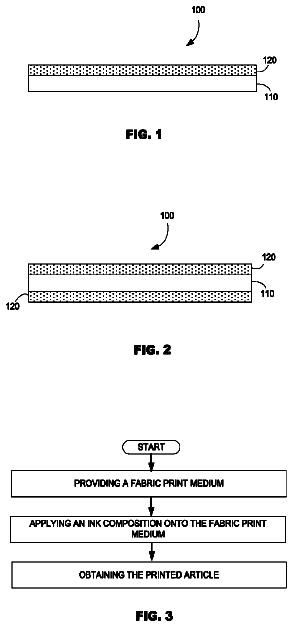
A fabric print medium containing a fabric base substrate and a primer layer composition applied to the fabric base substrate.
US 9,771,280 B2 · Assignee: Foret Plasma Labs, LLC · Inventors: Foret; Todd
Sheet 1 of 19 from the published document. All sheets in the USPTO PDF
The present invention provides a system, method and apparatus for treating a liquid by providing a santitary type stainless steel hydrocyclone, flowing the liquid through the hydrocyclone, and turning on a plasma torch attached to the hydrocyclone such that a plasma arc irradiates the liquid. The hydrocyclone can be a forward flow hydrocyclone, a reverse flow hydrocyclone, a through flow hydrocyclone, a hydrocyclone pump or a volute.
Without limiting the scope of the invention, its background is described in connection with treating liquids in particular drinking water, wastewater, beverages, juices, milk, emulsions, ballast water, bilge water, cooling tower water, process water, mill water, raw sewage, crude oil, hydrocarbon streams, black liquor and any pumpable liquid, as an example. There are various liquid streams that must be treated or processed in order to meet quality control standards or discharge permit requirements. For example, drinking water may be considered a product that must meet strict treatment requirements such as disinfection in order to render the water safe for human consumption. Likewise, there are other contaminants which may affect the quality of the water, such as iron, arsenic, hydrogen sulfide, organics and turbidity. Once the drinking water leaves the faucet at a residential location it
1 of 19 drawing sheets so far from the published document, cropped to the drawing. Every sheet is in the USPTO PDF.
What the patent claimed, word for word. All of it is now free to use.
The present invention relates generally to the field of treating liquids, and more particularly, to a method, system and apparatus for treating liquids with wave energy produced from plasma.
Without limiting the scope of the invention, its background is described in connection with treating liquids in particular drinking water, wastewater, beverages, juices, milk, emulsions, ballast water, bilge water, cooling tower water, process water, mill water, raw sewage, crude oil, hydrocarbon streams, black liquor and any pumpable liquid, as an example. There are various liquid streams that must be treated or processed in order to meet quality control standards or discharge permit requirements. For example, drinking water may be considered a product that must meet strict treatment requirements such as disinfection in order to render the water safe for human consumption. Likewise, there are other contaminants which may affect the quality of the water, such as iron, arsenic, hydrogen sulfide, organics and turbidity.
Once the drinking water leaves the faucet at a residential location it is now referred to as wastewater. Wastewater must also be treated in order to remove contaminants prior to discharge. One treatment method that is rapidly gaining in popularity is the use of UV radiation for disinfecting wastewater. Likewise, it is also being used for disinfecting drinking water. Another application that is being used in combination with UV radiation is the addition of an oxidant such as hydrogen peroxide or ozone in order to form hydroxyl radicals.
There are several major water streams that have gained widespread attention within the past few years. First, when left untreated, combined sewer overflows (CSO) and stormwater affect receiving streams. During heavy rainfall the shear volume of stormwater that must be treated has challenged engineers, scientists and municipalities. Two pollutants commonly found in CSO and stormwater runoff are floatables and pathogens. The US EPA, municipalities, scientists and engineers are currently searching for an extremely rugged CSO and stormwater treatment system that can both filter and disinfect prior to discharge to receiving streams.
Another water discharge that has challenged the marine water treatment industry is water discharged during ballasting operations for large ships. The problem with ballast water is that it may carry non-indigenous species that when discharged into a new environment can literally overwhelm and eradicate other lifeforms within that ecosystem. Thus, ballast water must now be disinfected prior to release. Likewise, ballast water may contain oil and grease residuals which must be removed prior to discharge.
Hydrocarbon contaminants, especially water soluble organics (WSO) have plagued another industry that operates in a marine environment. Offshore Oil and gas production platforms produce copious amounts of water along with the oil and gas. The produced water often contains WSO which must be removed from the water prior discharge. Although mechanical separators, such as hydrocyclones, can remove the insoluble hydrocarbon fraction, the soluble organics require extensive as well as expensive treatment methods such as acid extraction.
At land production wells, another contaminant, salt must be removed via evaporation or reverse osmosis prior to discharge or must be disposed via deep well injection. Likewise, when a well is drilled and then fractured, the flowback water must be treated prior to discharge.
Typically, most municipal water treatment facilities, both drinking water and wastewater incorporate some form of oxidation. This may be in the form of biological oxidation or addition of an oxidant such as chlorine, bleach or ozone. Many industrial wastewater streams have a very high chemical oxidation demand (COD). Thus, the water must be pretreated prior to discharge to a biological oxidation wastewater treatment plant.
One such industrial process stream is spent caustic produced from ethylene plants. Another oxidation process, wet air oxidation, is commonly used to oxidize the organics within spent caustic. Wet air oxidation consists of adding oxygen to the stream then heating and pressurizing the stream in order to oxidize the containments. Due to the high pressures and temperatures coupled with the addition of oxygen, exotic metals must be used in order to prevent corrosion, another form of oxidation.
Two other streams found in another industry, the pulp and paper industry, must be oxidized prior to use. First, pulp is oxidized to remove color. The pulping liquors must be oxidized in order to recover the valuable chemicals. However, the black liquor must be evaporated to remove access water that will not support combustion or oxidation of the black liquor. Likewise, the pulp must be separated and filtered in order to remove fines.
A common mechanical separator used in pulp and paper mills, on drilling rigs, in the mining industry and the oil, gas and oilsands industry is the hydrocyclone. Hydrocyclone separators are commonly used for phase separation purposes. Particles or fluids with a different density than water or the bulk liquid can be separated utilizing centripal force by means of a hydrocyclone. Hence, if the fluid is a liquid, a cyclone separator is typically referred to as a hydrocyclone, regardless if the bulk liquid is water, crude oil, gasoline, drilling fluid or any other liquid. And if the bulk fluid is a gas, then it is commonly referred to as a cyclone separator.
Hydrocyclones are normally classified according to flow direction. For example, referring to prior art hydrocyclones as shown in FIG. 13 , a forward flow hydrocyclone A discharges the accepts 1302 in the same axial direction as the bulk flow. The rejects 1304 are reversed and exit opposite of the bulk flow direction. Reverse Flow Hydrocyclones B discharges the accepts 1302 via a vortex finder and must reverse its axial direction with respect to initial bulk flow. A Throughflow Hydrocyclone C discharges both its accepts 1302 and rejects 1304 in the same axial direction of the bulk liquid flow. In all three hydrocyclones the whirl, swirl or vortex flow direction remains unchanged with respect to the initial rotation imparted on the fluid via the volute—clockwise or counterclockwise.
It is well known and well understood that the hydrocyclone forms a gas core in the center if open to atmosphere or a gas is injected into the hydrocyclone. The gas seeks the center of the hydrocyclone, since air or gases are less dense than water. Likewise, solids and liquids that are more dense than water will be forced outward and ejected through the apex valve and thus can be separated from the bulk liquid. Also, the less dense gas and water are ejected and discharged through the vortex finder.
All of the aforementioned liquids, in one manner or another, are treated with both separation and oxidation. For example, if oxidation will occur at elevated temperatures, such as wet air oxidation, the liquid must be preheated in order to start the reaction between dissolved oxygen and organics. The furnace tube used in wet air oxidation systems is very costly and transfers heat via conduction—through the wall of the pipe. For wet air oxidation to become a mainstream treatment technology another form of heating must be used in order to reduce both the operating costs as well as capital expense.
The present invention provides a simple and cost effective method, system and apparatus for treating water by synergistically combining and retrofitting an off-the-shelf plasma torch with a hydrocyclone. The present invention provides a plasma arc torch heat processing system for disposal of organic waste in a much smaller volume than conventional incinerators or plasma reactors, and at a higher processing rate to produce a benign gaseous discharge. The present invention also reduces the effect of thermal stresses associated with rapid startup and shut down of the plasma source. In addition, the present invention reduces labor intensive maintenance and operational costs associated with plasma thermal processing equipment as well as the associated facilities for waste infeed thereto.
More specifically, the present invention provides a method for treating a liquid by providing a santitary type stainless steel hydrocyclone, flowing the liquid through the hydrocyclone, and turning on a plasma torch attached to the hydrocyclone such that a plasma arc irradiates the liquid. The hydrocyclone can be a forward flow hydrocyclone, a reverse flow hydrocyclone, a through flow hydrocyclone, a hydrocyclone pump or a volute.
In addition, the present invention provides an apparatus for treating a liquid that includes a pump volute or hydrocyclone head, a throat connected to the pump volute or hydrocyclone head, and a plasma torch attached to the pump volute or hydrocyclone such that a plasma arc irradiates the liquid. Note that the apparatus can be used as a retrofit kit.
The present invention also provides a system for treating a liquid that includes a storage tank, a pump volute or hydrocyclone head, a throat connected to the pump volute or hydrocyclone head and a top of the storage tank and a plasma torch attached to the pump volute or hydrocyclone such that a plasma arc irradiates the liquid.
The present invention is described in detail below with reference to the accompanying drawings.
The above and further advantages of the invention may be better understood by referring to the following description in conjunction with the accompanying drawings, in which:
FIG. 1 is a diagrammatic, cross-sectional top view of a first embodiment Plasma Jet Vortex Mill Reactor;
FIG. 2 is a diagrammatic, cross-sectional top view of a second embodiment Hyper Plasma Jet Vortex Mill Reactor.
FIG. 3 is a diagrammatic, cross-sectional side view of a third embodiment Plasma Whirl Reactor;
FIGS. 3A, 3B and 3C are diagrammatic, cross-sectional side views of an embodiment Plasma Whirl Reactor illustrating the sequence for forming a Plasma Whirl;
FIG. 4 is a diagrammatic, cross-sectional side view of a fourth embodiment Plasma Jet Pancake Mill Reactor;
FIG. 5 is a diagrammatic, cross-sectional side view of a fifth embodiment Plasma Fluid Energy Mill Reactor;
FIG. 6 is a diagrammatic, cross-sectional side view of a sixth embodiment Hyper Plasma Jet Cyclone Separator Reactor;
FIG. 6A is a diagrammatic, cross-sectional side view of another embodiment Hyper Plasma Jet Cyclone Separator Reactor;
FIG. 7 is a diagrammatic, cross-sectional side view of another embodiment Hyper Plasma Jet Mill Reactor;
FIG. 7A is a diagrammatic, cross-sectional side view of another embodiment Hyper Plasma Jet Tornado Eductor Reactor;
FIG. 8 is a diagrammatic, process flow of an embodiment Plasma Jet Mill Eductor & Scrubber/Quencher;
FIG. 9 is an illustration of an embodiment of the Plasma Whirl Reactor in an Ethylene Oxide Plant utilized as a Zero Release Method;
FIG. 10 is an illustration of an embodiment for Onsite Rig/Pad Flare Elimination, Diesel Emissions Treatment and Drill Cuttings Conversion to Flyash with a Plasma Whirl Reactor;
FIG. 11 is an illustration of an embodiment of the Plasma Whirl Reactor for Upgrading Crude at the Wellhead;
FIG. 12 is an illustration of an embodiment of a Plasma Whirl Reactor for Treating Radioactive Waste;
FIG. 13 illustrate various Hydrocyclones in accordance with the prior art;
FIG. 14 is a Plasma Whirl Forward Flow Hydrocyclone in accordance with one embodiment of the present invention;
FIG. 15 is a Plasma Whirl Reverse Flow Hydrocyclone in accordance with another embodiment of the present invention;
FIG. 16 is a Plasma Whirl Through Flow Hydrocyclone in accordance with yet another embodiment of the present invention;
FIG. 17 is a Plasma Whirl Hydrocyclone Pump in accordance with another embodiment of the present invention; and
FIG. 18 is a Plasma Whirl Volute in accordance with another embodiment of the present invention.
While the making and using of various embodiments of the present invention are discussed in detail below, it should be appreciated that the present invention provides many applicable inventive concepts that can be embodied in a wide variety of specific contexts. The specific embodiments discussed herein are merely illustrative of specific ways to make and use the invention and do not delimit the scope of the invention. The discussion herein relates primarily to treating water, but it will be understood that the concepts of the present invention are applicable to treating any liquid.
The term “wave energy” is used herein to include radiation as well as wave energies transmitted by various mediums, and embraces electromagnetic waves or radiations; sonic, supersonic, and ultrasonic waves; neutrons, protons, deuteron, and other corpuscular radiations. The term “electromagnetic waves” includes, e.g., X-ray and gamma-ray, ultraviolet, infra red, and visible light rays, microwave, and both short electric and radio waves.
The present invention encompasses methodology and apparatuses configured for forming and utilizing a plasma torch in combination with a hydrocyclone for treating liquids. For purposes of interpreting this disclosure and the claims that follow, a “plasma whirl hydrocyclone or volute” is defined as an angular momentum generator in which a plasma torch is synergistically used with a whirling liquid to produce either chemical or thermal reactions which aid in both separation and oxidation. Likewise, the term “treating” is defined herein to include but not limited to pyrolysis, gasifcation, cracking, combustion, desorption and incineration.
Other embodiments of the present invention encompass methodology and apparatuses configured for forming and utilizing plasma jet for one or more of comminution, chemical reaction and separation in a single reactor system. For purposes of interpreting this disclosure and the claims that follow, a “plasma whirl comminution reactor” is defined as a reactor in which comminution and conversion of matter occurs therein. This is achieved because of the plasma's kinetic energy traveling at a high velocity in a vortex as well as the characteristics associated with a plasma (high temperature, radicals, free electrons, ions, etc). The high velocity plasma jet used in the present invention simultaneously subjects material to comminution and chemical reaction or conversion. The term “comminution” as used herein can be considered to be generic to all the terms ordinarily applied to the subject matter of the present invention such as grinding, crushing, grating, granulating, milling, disintegration, attrition, trituration, pulverization, etc. In its broadest meaning, the term comminution, as used herein, will also mean atomization. The terms vortex, cyclone, tornado, whirlpool, whirl, swirl, etc. are used interchangeably herein. These terms refer to a mass of fluid with a whirling or circular motion that tends to form a cavity or vacuum in the center of the circle and to draw toward this cavity or vacuum bodies subject to its action. In other words, the term “whirl, vortex, tornado or cyclone” as used in the present invention applies to a region within a body of fluid in which the fluid elements have an angular velocity or angular momentum. The term “chemical conversion” as defined herein includes the terms cracking, reforming, gasification, combustion, oxidation, reduction, etc. Simply put a chemical conversion with respect to the present invention means a “chemical reaction.” As defined herein, plasmas are ionized gases which can be formed from DC plasma torches, microwave plasma torches, inductively coupled plasma torches, AC plasma torches, electron beams or any other means which will generate an ionized gas. In its broadest meaning the plasma may be generated from any wave energy apparatus or method capable of producing an ionized gas. Matter as defined herein refers to the four states of matter; solids, liquids, gases and/or plasmas.
As described below in reference to FIGS. 1-12 , a plasma whirl kinetic energy comminution reactor uses a high velocity plasma jet fluid to create a plasma whirl for comminuting matter while chemically reacting the matter. Likewise, when operated in another mode, the plasma jet vortex mill reactor utilizes a high velocity plasma jet fluid to create a plasma vortex for chemically reacting matter and separating the products of the reaction of the matter.
FIG. 1 is representation of a Plasma Jet Vortex Mill Reactor. Plasma torches are aligned tangentially to create angular momentum that forms a plasma vortex. Solid matter, for example Municipal Solid Waste (MSW), drill cuttings, red mud, coal fines, petroleum coke, WEEE, etc, is conveyed into an inlet for simultaneous comminution and reaction. The chemical reaction of the solid matter may be based upon several variables such as, the solid matter's chemical composition, the fluid used in the plasma torches, the temperature of the reactor and the flow rates of the solid matter and the fluid. For example, if water or steam is used as the fluid in the plasma torch and the solid waste is coal, the end reaction maybe ash, hydrogen and carbon monoxide, hydrogen sulfide, chlorine and other contaminants. However, if carbon dioxide is used as the plasma torch fluid and the solid waste is carbon or coke, the end reaction may be ash and carbon monoxide. The carbon monoxide may be reformed with steam in the water gas shift reaction to produce hydrogen and carbon dioxide or may be used or sold as a chemical feedstock. The products of the reaction are flowed to an outlet for further treatment such as in a scrubber, amine unit for removing CO.sub.2 or for direct use. If CO.sub.2 is captured in an amine unit the CO.sub.2 can be recycled back into the plasma torch.
It will be understood that the present invention can utilize a typical cyclone separator as the shell or reactor vessel. In this embodiment of the present invention, the Plasma Jet Vortex Mill Reactor, also allows for separation of the ash or solid particulate matter from the gases (hydrogen, carbon monoxide, carbon dioxide). This occurs in one stage or vessel.
The present invention comprises a novel method for comminuting and chemically converting a solid carbon source into a chemical feedstock or fuel in one reaction vessel. Additionally, the present invention also provides a novel method for comminuting, reacting or converting, and separating a solid carbon source into a chemical feedstock or fuel and ash byproduct in one reaction vessel. Pretreatment of the coke, coal or carbon sources is not necessary. Dewatering is not necessary if the reactor is operated in a steam reforming mode.
The present invention can advantageously used as a skid or trailer mounted modular plasma reactor, having a relatively small footprint yet it can effectively comminute, react and separate a very large volume of material at extremely high flow-rates. For example, again referring to FIG. 1 , by installing a plurality of plasmas torches (eight
will be used in this example), such as Westinghouse Plasma Corporation's MARC-11 plasma torch, which are aligned tangentially, then the Plasma Jet Vortex Mill Reactor may be capable of treating extremely large volumes of waste. It will be understood that more or less than 8 torches can be used to obtain the desired comminution and chemical reaction or conversion.
The treatment rate calculated for using eight
Westinghouse Plasma Corporation'ss Torches in the present invention for MSW and ASR can range from 230 to 5,760 tons per day. These figures are based upon the nominal power of 300 kW-3,000 kW for the MARC-11 plasma torch in addition to the tests conducted for gasification of MSW and ASR. For MSW and ASR, the plasma torch power ranges from 100 kW to 250 kW per ton/hour.
The novel plasma jet vortex mill reactor of the present invention provides a viable solution for handling solid waste matter problems. For example, large volumes of solid waste matter are produced in oil & gas exploration, petroleum refineries, coal burning power plants, alumina plants, landfills, automobile shredding facilities, pulp and paper mills, and sugar mills. The waste matter from these facilities vary in particle size and chemical composition. Examples of the waste matter are drill cuttings, petroleum coke, coal fines/unburned carbon on flyash, red mud, MSW, ASR, wood chips/bark, and bagasse.
Normally, petroleum refineries have at least two delayed cokers for cracking the resid to coke and light ends. This allows cutting of the coke in the filled coke drum while the other coke drum is in operation. This process flow design allows for continuous operation of the refinery. In the present invention, the cut petroleum coke can be conveyed directly to the Plasma Jet Vortex Mill Reactor without having to be stockpiled or stored. Additionally, the Plasma Whirl Comminution Reactor can be operated with steam to produce syngas for use in the refinery.
Turning now to FIG. 2 , a Hyper Plasma Jet Vortex Mill Reactor is shown. The Plasma Torch, such as a Microwave Driven Plasma Torch, provides free electrons and conductive ionized gases to the reactor. Microwave Driven Plasma Torches (MIDJet™) are available from Physical Sciences, Inc. (PSI) of Andover, Mass. PSI's MIDJet™ is a microwave plasma torch that has no electrodes to wear out. A comminution fluid is conveyed into and enters the reactor via a combined radio frequency (RF) Coil and jet nozzle ring. Although shown as a combined unit, it will be understood that the RF Coil may be separate from the jet nozzle ring. The jets are arranged tangentially or in a means so as to initially start and preferably maintain a vortex. This elongates and constricts the plasma from the MIDJet™. When an AC current is applied to the RF Coils the microwave plasma volume increases dramatically. The rapid expansion of the plasma volume increases velocity. Thus, the initial angular velocity is dramatically increased which immensely increases angular momentum within the reactor.
This imparts a novel, unobvious and very unique method for comminution, chemical reactions and separation. Since it is well known and well understood that plasma jets can obtain velocities greater than 3,000 meters/second with high energy densities, then the plasma jet can be converted to angular momentum and energy. Not being bound by theory, it is believed that as the RF coils increase the plasma volume the velocity will increase dramatically without an increase in fluid flow. It is also believed that by centrally locating a plasma source (microwave plasma torch), the centrally located plasma region will remain in an extremely highly activated state. This is so for several reasons. First, the vortex creates a central void or vacuum. Second, since in a vacuum the molecules will be farther apart thus, less collisions will occur. An electron beam can be used for creating the central ionized gas region in lieu of a microwave driven plasma torch. An ideal electron beam source for the present invention is a non-vacuum electron beam welder.
The highly activated ionized gas center allows for complete dissociation of all matter entering into it. The molecules, atoms or radicals with a mass low enough to enter into the central vacuum or “eye of the tornado” may be fully dissociated if a sufficient amount of energy is applied to the Hyper Plasma Jet Vortex Mill Reactor. Likewise, large and more dense particulate matter will be flung toward the outside of the vortex.
In kinetic energy comminutation devices, such as a jet mill or fluid energy mill, a gas is used in combination with angular momentum to disintegrate particles into smaller particles. A jet mill uses stored potential energy to create angular momentum. Potential energy is stored within a compressed gas such as compressed air or steam. However, the compression stage occurs in a separate and distinct process/apparatus such as a boiler or compressor. It is well known that air compression is an inefficient means for storing energy. The jet mill is utilized for particle comminutation, disintegration or grinding.
Another device that takes advantage of angular momentum is a cyclone separator. Both the jet mill and cyclone separator are utilized for comminutation, drying and separating but not as a chemical reactor.
On the other hand, the present invention imparts angular momentum to particles within the reactor by means of increasing the plasma volume. In comparison, this would be akin to increasing fuel flow into a combustion turbine or any internal combustion engine. However, in contrast, the present invention's energy source is stored and transferred into the reactor via electrons and photons or quite simply wave energy. It is the wave energy that is the means for imparting a sufficient amount of angular momentum to the reactor and not simply just the gas flowing into the reactor.
In part, the novelty of the present invention leads to unexpected results due to the combined effects of a jet mill with that of a plasma torch. It is unexpected that a plasma torch in combination with another plasma generation device, coupled to impart angular momentum in a vessel, allows for a reduction in the flow rate of the jet fluid. This unexpected combination can be explained as follows:
1. An initial wave energy generating means provides wave energy to the reactor.
2. At least one other wave energy generating means is used to increase angular momentum within the reactor.
3. As the second wave energy generating means is energized the ionized gases increase in temperature.
4. Due to the increase in temperature the gases expand rapidly.
5. The increase in gas volume increases velocity.
6. Due to the design of the reactor, the plasma velocity is transferred into angular momentum. Thus angular momentum is increased within the vessel by not having to increase gas flow rate or solid flow rate to the reactor.
In essence, waste or fluid flow rate to the vessel can be stopped or recycled using valves or any other suitable means and the reactor can be operated similar to a giant light bulb or continuous recycling reactor. This “giant light bulb” mode of operation would be a closed loop operation.
Another unexpected result of the present invention is the ease of controlling the reactor via electronics. This is contrasted to the difficulties in controlling modern day jet mills, pyrolysis, gasification, reforming and cracking reactors, and cyclone separators via fluid flow. The speed at which the present invention can be controlled is the speed of wave energy. By utilizing solid-state power supplies and microwaves the speed of electrons and the speed of microwave photons (speed of light in an atmosphere) are used. Current modern day practices utilize valves that may be electronically controlled and actuated, but the sealing or throttling device operates mechanically. This will best be explained in a gas flaring example.
Flaring waste gases is common in many industries. Flares may operate intermediately, all the time, automatically or with operator assistance. However, the flare ignition device, normally a pilot light, may operate continuously. This is similar to the pilot light on a gas stove or oven. The pilot light stays on all the time. When the gas valve for a burner on the stove is turned to the low, medium or high position, gas flows through the burners and is ignited by the pilot light.
In the present invention, as shown in FIG. 2 , the MIDJet™ (microwave plasma torch) or the wave energy source, acts similar to a pilot light. The gas or fluid for the plasma torch can be steam, VOCs, CO.sub.2, air, oxygen, hydrogen, nitrogen or any other fluid capable of being ionized and forming a plasma. If the wave energy source is an electron beam then a fluid is not necessary. Simply a stream of electrons acts as the pilot light. In the event of a plant upset, when VOCs or any other fluid is flowed to the reactor, the RF field is energized or more energy is applied to the RF Coil. The reactor can be designed to operate similarly to an electric motor in which as the load or torque increases on the motor's shaft more electricity is flowed through the windings to increase torque. It will be understood that many variations and automated control schemes can be utilized to automate the reactor. Some of the parameters that can be monitored to automate the reactor are temperature, flow rate, valve position, amps, volts, etc.
FIG. 3 is a representation of a Plasma Whirl Reactor of the present invention that illustrates the whirls that will be present in such a reactor and helps one with understanding the advantages of the present invention's plasma whirl reactor over conventional plasma systems. In comparison and contrast to a plasma whirl and to better understand “whirl” flow, an explanation of fire whirls can be found in the following publications from the U.S. Dept. of Commerce Technology Administration, National Institute of Standards and Technology (NIST):
NISTIR 6341 “Simulating Fire Whirls,”
NISTIR6427 “The Fluid Dynamics of Whirls—An Inviscid Model,” and
US Today Newspaper, Jun. 24, 2002 issue.
In order to demonstrate the wide variety of uses for the present invention, some of the figures hereof will be described in various preferred applications. For example, flares and solids found in the Oil & Gas Industry and biogas and MSW found at landfills. However, it will be understood that the present invention can be applied to many different applications in various industries. In addition, the present invention will be demonstrated in both cracking and reforming modes. Likewise, the present invention will be demonstrated in a carbon sequestration mode, which in turn allows for the production of a relatively clean hydrogen stream.
Turning again to FIG. 3 hereof there is illustrated a Plasma Whirl Reactor 100 that is comprised of a pilot plasma 101 , the pilot plasma elongated, constricted and whirled 101 A along the longitudinal axis and the plasma volume increased radially 101 B. A first wave energy source 102 generates the pilot plasma 101 and the second plasma 101 B is generated by a second wave energy generation means 105 , such as a Radio Frequency (RF) induction coil. A fluid B, such as flare gas, enters reactor 100 through inlet 103 . The flare gas or fluid B then flows through a serious of jets or slits 104 which are coupled to the reactor in a way to impart angular momentum 104 A to pilot plasma 101 . RF coils 105 may be energized before, during or after the entry of the flare gas or fluid B into the reactor 100 .
Next, several unsuspected but highly desirable results can occur. For example, angular momentum or the velocity of the whirl 104 A is increased due to adding potential energy in the form of electromagnetic radiation energy (photons or electrons) via the RF coils 105 . Thus, fluid B flow does not need to be increased to increase angular momentum 104 A as is common with jet energy mills. Also, the plasma volume increases dramatically due to forming the second plasma 101 B. However, the angular momentum and/or whirl 104 A effects the pilot plasma 101 A by constricting it radially while increasing its length along the longitudinal axis of the reactor 100 . This sequence of events is demonstrated in FIGS. 3A, 3B and 3C hereof.
In FIG. 3A , in lieu of using slits or jets, a squirrel cage fan 104 is utilized for imparting angular momentum or whirl 104 A to reactor 100 . Squirrel cage fan 104 is fixed in place (does not rotate) by any known attachment means, such as bolting, rivoting, welding, gluing, clamping, etc. Reactor 100 may be fabricated such that the squirrel cage fan 104 is an integral part of reactor 100 . This can be accomplished by machining, or molding, squirrel cage fan 104 as a part of reactor 100 . Fluid B flows into inlet 103 , which in this case is the annulus between the reactor wall and a refractory/EMR permeable wall 100 A. Squirrel cage fan 104 in the present invention operates opposite that of a typical blower that incorporates a squirrel cage fan. The purpose of the squirrel cage fan, jets, slits, nozzles or louvers 104 is to impart initial angular momentum 104 A within reaction chamber 100 B.
In FIG. 3B when the flare gas or fluid B flows through squirrel cage fan 104 angular momentum 104 A is created and imparts a desirable quality to the pilot plasma 101 . Due to the angular momentum and whirl 104 A pilot plasma 101 is now stretched and constricted into an elongated whirl plasma 101 A along the longitudinal axis of reactor 100 .
In FIG. 3C when RF coils 105 are energized the plasma volume increases radially to form a very large plasma 101 B. Once again the unexpected but extremely desirable quality of an increase in angular momentum is imparted to reactor 100 .
This additional attribute performs several functions with unexpected results. Again referring to FIG. 3C a second fluent material C enters the reactor via inlet 106 . Due to angular momentum and whirl 104 A in combination with centrifugal force the fluent material is comminuted by particle to particle collisions, heat and the high velocity plasma. In addition, the secondary large plasma 101 B provides heat, wave energy, radicals and ions for chemically reacting reactants into products.
Not being bound by theory, it is also believed that the Plasma Whirl Reactor of the present invention can be used to separate materials as well as to increase residence time within the reactor 100 for particulate matter. Dense particulate matter is separated from less dense matter, such as light gases (hydrogen) due to angular momentum 104 A which forms centrifugal force within the reactor 100 . The less dense matter may be entrained within the elongated pilot plasma 101 A. The dense matter is entrained within the peripheral of the large plasma 101 B. The reactor can be designed such that the all matter exiting the reactor must pass through the elongated pilot plasma 101 A.
Another unexpected but desirable result occurs when outlet E and reactor 100 are modified in size and shape to resemble a cone, cyclone separator or jet mill. By referring to FIGS. 1, 2, 4, 5, 6, 6A, 7, and 7A the reactor may be constructed similar to a cyclone separator and/or a jet energy mill. This attribute performs several functions with unexpected results. It should be noted that the terms “matter” and “particulate matter” as used herein refers to particles, ions, atoms, molecules and elements in solid, liquid, gas or plasma states. Once again, not being bound by theory, it is believed that more dense matter will remain in the outer portion of the whirl, while less dense matter will remain within the central vortex of the plasma whirl. Thus, matter of different densities can be separated from the main flow via the vortex by designing the reactor similar to a cyclone separator.
The plasma whirl reactor of the present invention can easily replace a flare to achieve zero emissions, discharges or releases. For example, during upsets in a refinery or petrochemical plant an operator may, send a feedstock stream, such as methane to a flare. However, if the present inventions plasma whirl reactor were in place, the operator would have an alternative to flaring and releasing emissions to the atmosphere.
The Plasma Whirl Reactor of the present invention can easily be configured for intermittent operations such as replacing a flare. First, pilot plasma source 102 can be an extremely low powered source. One example is a 6 kW MIDJet™. Another example is a lower powered non-transferred arc plasma cutting torch. The plasma carrier gas may be selected from steam, CO.sub.2, air, oxygen, nitrogen, hydrogen, helium, VOCs or any other gas capable of being ionized. For the sake of simplicity since many flares are steam assisted, then steam will be used in the following example.
The Plasma Whirl Reactor of the present invention may be operated in a cracking mode, by increasing or turning on power to RF coils 105 . Since pilot plasma 101 is already formed, by energizing coils 105 , this will form the large plasma volume 101 B. As soon as the feedstock from the plant upset flows into inlet 103 and through jets 104 , several processes occur simultaneously. First, angular momentum increases. This forms the elongated pilot plasma 101 A. Second, the hydrocarbon (HC) feedstock, such as methane or an ethane/propane mix, commonly used for ethylene production, is cracked into hydrogen and carbon provided that the feedstock flow B is far greater than the steam flow A into pilot plasma torch 102 which produces the pilot plasma 101 . It will be understood that pilot plasma 101 may utilize the HC as carrier gas A in lieu of steam.
It is believed that the cracked products, hydrogen and carbon can easily be separated from each other, by designing the Plasma Whirl Reactor similar to that represented in FIG. 6A hereof. The lighter hydrogen will remain in the central vortex while the carbon will be forced to the outside of the whirl. The hydrogen can exit the reactor via a top outlet while the carbon exits via a bottom outlet. It will be understood that a pilot electron beam can be used in lieu of the pilot plasma torch. Thus this would eliminate carrier gas A.
The Plasma Whirl Reactor of the present invention can be immediately switched to a CO.sub.2 reformer for the production of syngas. Referring back to FIG. 3 hereof, if the plant desires to produce syngas in lieu of hydrogen and carbon, the operator can flow CO.sub.2 into reactor 100 via inlet 110 . It will be understood that the CO.sub.2 can be premixed with feedstock stream 103 , prior to entry into reactor 100 . A plant that has a large CO.sub.2 point source emission such as an ethylene oxide plant can utilize the CO.sub.2 in the present invention for production of syngas. The syngas can then be transferred via pipeline to a nearby refinery of chemical plant for use as a chemical feedstock. The use of the present invention in this application eliminates the CO.sub.2 emission at an ethylene oxide plant. If the Plasma Whirl Reactor is operated at a temperature greater than 1000° C., the CO.sub.2 reforming reaction is exothermic. Thus, any refinery or industry in dire need of hydrogen can utilize any HC stream to efficiently produce hydrogen with the present invention's Plasma Whirl Reactor.
As previously stated, the Plasma Whirl Reactor of the present invention can be configured in accordance with FIGS. 1 through 7A hereof or in any manner that will provide a source for an ionized gas that provides a means for angular momentum. The product from the chemical reaction of the reactants in the Plasma Whirl Reactor of the present invention can be further scrubbed or purified in accordance with FIG. 8 hereof.
Referring to FIG. 8 hereof, the syngas produced from plasma whirl reactor 100 is conveyed into eductor 200 by means of suction provided by a quenching fluid that flows into a quench/scrubbing tower 300 . The quenching/scrubbing fluid may be selected from the group consisting of water, amines, emulsions, hydrocarbons, organic fluids, caustic soda, calcium oxide, red mud, and any fluid that will quench and scrub the syngas. Pressurized fluid is provided to eductor 200 by means of a pump or compressor 400 via pipe 401 .
The description continues in the full USPTO document.
About 6,450 words. The USPTO PDF has it with every drawing.
Fees are due 3.5, 7.5 and 11.5 years after grant. This patent expired on September 26, 2025, so the fee marked "not paid" was the one that went unpaid.
System, method and apparatus for treating liquids with wave energy from plasma
Filed Apr 2007 · published Nov 2007System, method and apparatus for treating liquids with wave energy from plasma
Filed Apr 2007 · granted Nov 2016SYSTEM, METHOD AND APPARATUS FOR TREATING LIQUIDS WITH WAVE ENERGY FROM PLASMA
Filed Sep 2016 · published Jan 2017System, method and apparatus for treating liquids with wave energy from plasma
Filed Sep 2016 · granted Sep 2017Earlier publications, parents and continuations. None of them can still be enforced, or this patent would not be listed.
Prior art cited by the examiner or applicant. Useful when you check your own idea for novelty.
Everything on this page comes from the documents linked above.