Field of application
The invention relates to network coordination apparatus for configuring one or more network entities, but not exclusively limited to configuring one or more network entities within a self-organising network.
Background of application
A communication system can be seen as a facility that enables communication sessions between two or more entities such as mobile communication devices and/or other stations associated with the communication system. A communication system and a compatible communication device typically operate in accordance with a given standard or specification which sets out what the various entities associated with the system are permitted to do and how that should be achieved. For example, the manner how the communication device can access the communication system and how communications shall be implemented between communicating devices, the elements of the communication network and/or other communication devices is typically defined.
In a wireless communication system at least a part of communications between at least two stations occurs over a wireless link. Examples of wireless systems include public land mobile networks (PLMN), satellite based communication systems and different wireless local networks, for example wireless local area networks (WLAN). In wireless systems a network element or network entity (NE) or access node is provided by a base station. The radio coverage area of a base station is known as a cell, and therefore the wireless systems are often referred to as cellular systems. In some systems, for example a 3GPP standard system, a base station access node is called Node B (NB) or an enhanced Node B (eNB).
A user can access the communication system by means of an appropriate communication device. A communication device of a user is often referred to as user equipment (UE). A communication device is provided with an appropriate signal receiving and transmitting arrangement for enabling communications with other parties. A communication device may be arranged to communicate, for example, data for carrying communications such as voice, electronic mail (email), text message, multimedia, for enabling internet access and so on. Users may thus be offered and provided numerous services via their communication devices. The communication connection can be provided by means of one or more data bearers.
In wireless systems a communication device provides a transceiver station that can communicate with the access node and/or another communications device. A communication device or user equipment may also be considered as being a part of a communication system. In certain applications, for example in ad-hoc networks, the communication system can be based on use of a plurality of user equipment capable of communicating with each other.
Network management is a complex task. Complexity arises on the one side from the number of network elements (NEs) that have to be deployed and managed, and on the other side from interdependencies between the configuration and the status of the deployed network elements in terms of performance, faults, etc. In a heterogeneous network the variety of deployed technologies and their proprietary operational paradigms are difficult to handle. A heterogeneous network for example, can be a network consisting of a multitude of access technologies, and different (cell) layers within these access technologies. A layer in a wireless network access technology is characterised by for example the size or geographical area covered by one network element, the transmission power, the bandwidth, the maximum throughput. Examples of cell layers are macro cells, micro and pico cells (for hotspot and enterprise coverage), and indoor cells. Furthermore some cells may only serve closed user groups.
The configuration, optimisation and troubleshooting of the management of the network therefore requires high expertise and operational management workflows to be typically performed by human operators supported by software tools. However, such manual and semi-automated management is time-consuming, error-prone, and potentially unable to react quickly enough to network changes and thus expensive.
It has been a goal of network management designers to attempt to automate operation, administration and management (OAM) functions by the deployment of “Self Organising Networks” (SON). While SON concepts are generically applicable, these focus of developments has been to Radio Access Networks (RAN) due to the large number of NE (radio base stations) distributed over large geographical areas (and thus the incurred cost to doing remote and on-site management activities). In particular, for the long term evolution (LTE) and long term evolution-advanced (LTE-A) radio access network (RAN) standards such as evolved universal mobile telecommunications system (UMTS) Terrestrial Radio Access Network (E-UTRAN), SON is considered a crucial building block, due to the anticipated high degree of distribution and heterogeneity. In other words in such networks there is expected to be a wide range of telecommunications standards being employed such as concurrent operation of 2G/3G/LTE/LTE-A network elements. Furthermore the LTE networks are believed to also be heterogeneous in structure, for example employing LTE multi-layer structures where there can be pico cells, micro cells, and macro cells all operating over the same geographical range.
Typically the SON is implemented by the application of SON functions which monitor, plan and enforce control over network elements. However because the operation of SON functions is individual and dynamic (i.e., not pre-planned), the application of SON function instances can have run-time interactions with other SON functions instances.
Statement of application
In accordance with an embodiment there is provided a method comprising: determining within a measurement interval at least one effective network control function instance; selecting a subsequent measurement interval measurement data for at least one succeeding function; and executing the at least one succeeding function dependent on the subsequent measurement interval measurement data.
Selecting a subsequent measurement interval measurement data for at least one succeeding function may comprise: selecting a subsequent measurement interval measurement data with an associated unset or reset measurement flag.
The method may further comprise: setting a measurement flag dependent on determining the effective network control function instance within the measurement interval; and resetting/unsetting the measurement flag on determining a succeeding measurement interval following an end of the at least one function instance visibility delay period.
Selecting a subsequent measurement interval measurement data for at least one succeeding function may comprise: extending at least one function instance visibility delay period to end substantially at the end of the measurement interval; and selecting the subsequent measurement interval following an end of the at least one function instance visibility delay period to provide measurement data.
Extending the at least one function instance visibility delay period to end substantially at the end of the measurement interval may comprise: determining the end of a visibility delay period; determining a remaining measurement interval period; and determining a visibility delay period extension for the remaining measurement interval period.
Selecting a subsequent measurement interval measurement data for at least one succeeding function may comprise: extending a succeeding function protection time period to end substantially following the end of the subsequent measurement interval; and selecting the subsequent measurement interval to provide measurement data.
Extending the succeeding function protection time period to end substantially following the end of the subsequent measurement interval may comprise: determining an end of a visibility delay period; determining a remaining measurement interval period; and determining a protection delay period extension for the remaining measurement interval period.
Selecting a subsequent measurement interval measurement data for at least one succeeding function may comprise: controlling the measurement interval period; and selecting the controlled subsequent measurement interval to provide measurement data.
Controlling the measurement interval period may comprise: pausing the generation of further measurement interval periods dependent on determining within a measurement interval at least one effective network control function instance; and generating a subsequent measurement interval dependent on determining the at least one effective network control function instance.
According to a second aspect there is provided an apparatus comprising: an instance determiner configured to determine within a measurement interval at least one effective network control function instance; a data selector configured to select a subsequent measurement interval measurement data for at least one succeeding function; and an instance executor configured to execute the at least one succeeding function dependent on the subsequent measurement interval measurement data.
The data selector may be configured to select a subsequent measurement interval measurement data with an associated unset or reset measurement flag.
The apparatus may comprise: a measurement flag setter configured to set a measurement flag dependent on determining the effective network control function instance within the measurement interval; and a measurement flag clearer configured to reset/unset the measurement flag on determining a succeeding measurement interval following an end of the at least one function instance visibility delay period.
The data selector may be configured to: extend at least one function instance visibility delay period to end substantially at the end of the measurement interval; and select the subsequent measurement interval following an end of the at least one function instance visibility delay period to provide measurement data.
The data selector configured to extend the at least one function instance visibility delay period to end substantially at the end of the measurement interval may comprise: a visibility delay period determiner configured to determine the end of a visibility delay period; a measurement period determiner configured to determine a remaining measurement interval period; and a visibility delay extender configured to determine a visibility delay period extension for the remaining measurement interval period.
The data selector may be configured to: extend a succeeding function protection time period to end substantially following the end of the subsequent measurement interval; and select the subsequent measurement interval to provide measurement data.
The data selector configured to extend the succeeding function protection time period to end substantially following the end of the subsequent measurement interval may comprise: a visibility delay period end determiner configured to determine an end of a visibility delay period; a measurement period determiner configured to determine a remaining measurement interval period; and a protection delay period extender configured to determine a protection delay period extension for the remaining measurement interval period.
The data selector may be configured to: control the measurement interval period; and select the controlled subsequent measurement interval to provide measurement data.
The data selector configured to control the measurement interval period may comprise: an interval clock interrupter configured to pause the generation of further measurement interval periods dependent on determining within a measurement interval at least one effective network control function instance; and an interval clock starter configured to generate a subsequent measurement interval dependent on determining the at least one effective network control function instance.
According to a third aspect there is provided apparatus comprising at least one processor and at least one memory including computer code for one or more programs, the at least one memory and the computer code configured to with the at least one processor cause the apparatus to at least perform: determining within a measurement interval at least one effective network control function instance; selecting a subsequent measurement interval measurement data for at least one succeeding function; and executing the at least one succeeding function dependent on the subsequent measurement interval measurement data.
Selecting a subsequent measurement interval measurement data for at least one succeeding function may cause the apparatus to perform selecting a subsequent measurement interval measurement data with an associated unset or reset measurement flag.
The apparatus may be configured to perform: setting a measurement flag dependent on determining the effective network control function instance within the measurement interval; and resetting/unsetting the measurement flag on determining a succeeding measurement interval following an end of the at least one function instance visibility delay period.
Selecting a subsequent measurement interval measurement data for at least one succeeding function may cause the apparatus to perform: extending at least one function instance visibility delay period to end substantially at the end of the measurement interval; and selecting the subsequent measurement interval following an end of the at least one function instance visibility delay period to provide measurement data.
Extending the at least one function instance visibility delay period to end substantially at the end of the measurement interval may cause the apparatus to perform: determining the end of a visibility delay period; determining a remaining measurement interval period; and determining a visibility delay period extension for the remaining measurement interval period.
Selecting a subsequent measurement interval measurement data for at least one succeeding function may cause the apparatus to perform: extending a succeeding function protection time period to end substantially following the end of the subsequent measurement interval; and selecting the subsequent measurement interval to provide measurement data.
Extending the succeeding function protection time period to end substantially following the end of the subsequent measurement interval may cause the apparatus to perform: determining an end of a visibility delay period; determining a remaining measurement interval period; and determining a protection delay period extension for the remaining measurement interval period.
Selecting a subsequent measurement interval measurement data for at least one succeeding function may cause the apparatus to perform: controlling the measurement interval period; and selecting the controlled subsequent measurement interval to provide measurement data.
Controlling the measurement interval period may cause the apparatus to perform: pausing the generation of further measurement interval periods dependent on determining within a measurement interval at least one effective network control function instance; and generating a subsequent measurement interval dependent on determining the at least one effective network control function instance.
According to a fourth aspect there is provided an apparatus comprising: means for determining within a measurement interval at least one effective network control function instance; means for selecting a subsequent measurement interval measurement data for at least one succeeding function; and means for executing the at least one succeeding function dependent on the subsequent measurement interval measurement data.
The means for selecting a subsequent measurement interval measurement data for at least one succeeding function may comprise means for selecting a subsequent measurement interval measurement data with an associated unset or reset measurement flag.
The apparatus may comprise: means for setting a measurement flag dependent on determining the effective network control function instance within the measurement interval; and means for resetting/unsetting the measurement flag on determining a succeeding measurement interval following an end of the at least one function instance visibility delay period.
The means for selecting a subsequent measurement interval measurement data for at least one succeeding function may comprise: means for extending at least one function instance visibility delay period to end substantially at the end of the measurement interval; and means for selecting the subsequent measurement interval following an end of the at least one function instance visibility delay period to provide measurement data.
The means for extending the at least one function instance visibility delay period to end substantially at the end of the measurement interval may comprise: means for determining the end of a visibility delay period; means for determining a remaining measurement interval period; and means for determining a visibility delay period extension for the remaining measurement interval period.
The means for selecting a subsequent measurement interval measurement data for at least one succeeding function may comprise: means for extending a succeeding function protection time period to end substantially following the end of the subsequent measurement interval; and means for selecting the subsequent measurement interval to provide measurement data.
The means for extending the succeeding function protection time period to end substantially following the end of the subsequent measurement interval may comprise: means for determining an end of a visibility delay period; means for determining a remaining measurement interval period; and means for determining a protection delay period extension for the remaining measurement interval period.
The means for selecting a subsequent measurement interval measurement data for at least one succeeding function may comprise: means for controlling the measurement interval period; and means for selecting the controlled subsequent measurement interval to provide measurement data.
The means for controlling the measurement interval period may comprise: means for pausing the generation of further measurement interval periods dependent on determining within a measurement interval at least one effective network control function instance; and means for generating a subsequent measurement interval dependent on determining the at least one effective network control function instance.
A computer program product stored on a medium may cause an apparatus to perform the method as discussed herein.
An electronic device may comprise apparatus as discussed herein.
A chipset may comprise apparatus as discussed herein.
Various other aspects and further embodiments are also described in the following detailed description and in the attached claims.
Summary of the figures
The invention will now be described in further detail, by way of example only, with reference to the following examples and accompanying drawings, in which:
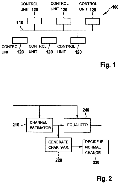
FIG. 1 shows a schematic representation of a network according to some embodiments;
FIG. 2 shows a schematic representation of a control apparatus according to some embodiments;
FIG. 3 shows an overview of the self-organising network according to some embodiments;
FIGS. 4 a to 4 c show schematic representations of components of the impact time with respect to an example self-organising network function according to some embodiments;
FIG. 5 shows an example time flow representation of the interaction of self-organising network functions;
FIGS. 6 a and 6 b show flow diagrams of the operation of the context determiner according to some embodiments;
FIG. 7 shows an example time flow representation of the interaction of self-organising network functions according to embodiments represented by the flow diagrams of FIGS. 6 a and 6 b;
FIG. 8 shows a flow diagram of the operation of the context determiner according to some further embodiments;
FIG. 9 shows an example time flow representation of the interaction of self-organising network functions according to embodiments represented by the flow diagram of FIG. 8 ;
FIG. 10 shows a flow diagram of the operation of the context determiner according to some further embodiments;
FIG. 11 shows an example time flow representation of the interaction of self-organising network functions according to embodiments represented by the flow diagram of FIG. 10 ;
FIG. 12 shows a flow diagram of the operation of the context determiner according to some further embodiments; and
FIG. 13 shows an example time flow representation of the interaction of self-organising network functions according to embodiments represented by the flow diagram of FIG. 12 .
Description of some embodiments of the application
In the following certain exemplifying embodiments are explained with reference to wireless or mobile communication systems serving mobile communication devices.
In particular the application describes self-organising network coordination between different independently operating SON functions. This can be performed, for example, within a SON coordinator. The SON coordinator detects and resolves potential conflicts between SON functions. This resolution can be performed, for example, by rejecting or delaying the execution of a SON function.
Before explaining in detail the certain exemplifying embodiments, certain general principles of a wireless communication system and the nodes thereof are briefly explained with reference to FIGS. 1 and 2 to assist in understanding of the herein described embodiments.
In a communication system 10 a user can be provided with a mobile communication device 1 that can be used for accessing various services and/or applications. The access can be provided via an access interface between the mobile communication device 1 and an appropriate wireless access system of a communication system 10 comprising an access node. An access node or network entity (NE) can be provided by a base station. FIG. 1 shows part of a radio access network (RAN), including a base station 2 . The term base station will be used in the following and is intended to include the use of any of these network access nodes or any other suitable network entity. The communication system 10 also comprises a self-organising network management entity (not shown). The self-organising network SON functions can be integrated into the OAM (Network Management) architecture and be communicated via the Itf-S: not standardised and Itf-N: standardised interfaces. In some embodiments the SON functions can also be physically integrated at the NE directly (this is a so-called distributed approach), or they can be integrated at the OAM system (this is a so-called centralised approach).
An appropriate mobile user device or station may be provided by any device capable of sending and receiving radio signals. Non-limiting examples include a mobile station (MS) such as a mobile phone or what is known as a ‘smart phone’, a portable computer provided with a wireless interface card or other wireless interface facility, personal data assistant (PDA) provided with wireless communication capabilities, or any combinations of these or the like. In some embodiments some devices are not “personal” devices directly “operated” by a human, but devices which are integrated within vehicles, goods, containers. In some embodiments these devices can be used for a range of operations such as goods and/or vehicle tracking, supporting delivery processes, or collecting and providing status data.
A mobile communication device is often called user equipment (UE). Each mobile device 1 and base station 2 may have one or more radio channels open at the same time and may receive signals from more than one source.
FIG. 1 shows a base station 2 having a cell area associated therewith and the base station 2 is connected to relay nodes 4 , 5 . Each relay node can establish a connection to the base station 2 or alternatively the relay nodes can share the same backhaul link. In the cell area of the base station 2 , there can be provided two relay nodes 4 and 5 , but it is noted that this is by way of example only. In practice there may be more or less than two relay nodes. In relaying a relay node (RN) is wirelessly connected to the radio-access network via a donor cell, that is the cell of base station 2 of FIG. 1 . FIG. 1 also shows neighbouring cells provided by another base station 3 which the relay nodes 4 , 5 are not connected to.
Relay nodes may be used, for example, in block of flats and other buildings, offices, warehouses and/or factories and/or in public places, for example in shopping malls, sports or exhibition halls or arenas, particular areas of cities, on moving platforms such as trains, ships, busses, aeroplanes and so on.
The relay nodes 4 , 5 , can be relatively low power nodes that may be deployed to provide enhanced indoor coverage, additional capacity at hotspots or cell edge regions. For example, in the case of indoor deployment, such an access point or node may be provided for example in apartment blocks or office buildings and hence there may be a relatively high density of such access nodes.
Returning to FIG. 1 , there is shown a gateway function 9 of the communication system 10 connecting a core network 11 and/or another network, application functions or services 12 . A packet data network may also be provided by means of appropriate gateway nodes. Regardless of the gateway arrangement, a communication device 1 can be connected to an external data network, for example the internet via the relay nodes 4 , 5 and/or the base stations 2 , 3 .
The base stations 2 , 3 can be typically controlled by at least one appropriate controller apparatus 6 . The relay nodes 4 , 5 are also typically controlled by at least one appropriate controller apparatus 13 , 14 . Furthermore the operation of these controller apparatus can in some embodiments be controlled by the self-organising network management entity not shown.
FIG. 2 shows an example self-organising network management controller apparatus for the network entities (relay nodes 4 , 5 or the base stations 2 , 3 ). The controller apparatus 6 is typically provided with at least one memory 31 , at least one data processor 32 and an input/output interface 34 as shown in FIG. 2 . The control apparatus 6 can further comprise a coordination function layer 33 . The control apparatus 6 can be configured to execute appropriate software applications to provide the desired control functions. The control apparatus 6 , can in some embodiments be provided in a node and comprising at least one memory and computer program code can be configured, with the at least one processor, to cause the node to communicate with other network entities to communicate control information. At least some of the processing blocks can in some embodiments be carried out by one or more processors in conjunction with one or more memories. The processing block may be provided by an integrated circuit or a chip set. The control apparatus can be interconnected with other control apparatuses.
A non-limiting example of mobile architectures where the herein described principles may be applied is known as the Evolved Universal Terrestrial Radio Access Network (E-UTRAN). Non-limiting examples of appropriate access nodes are a base station of such system, for example what is known as NodeB or eNB in the vocabulary of the 3GPP specifications. Other examples include base stations of systems that are based on technologies such as wireless local area network (WLAN) and/or WiMax (Worldwide Interoperability for Microwave Access). Access nodes can provide cellular system level base stations providing E-UTRAN features such as user plane Radio Link Control/Medium Access Control/Physical layer protocol (RLC/MAC/PHY) and control plane Radio Resource Control (RRC) protocol terminations towards mobile communication devices.
FIG. 3 shows a schematic overview of an example self-organising network management controller 251 or automated operation administration and management (OAM) function apparatus. With respect to the following examples the operation of the example self-organising network management controller focuses on the organisation of Radio Access Networks (RAN) and in particular for LTE and LTE-A RAN (E-UTRAN).
The self-organising network management controller 251 is shown operating under a pre-planned or network design layer 201 and operating on the network layer 277 .
The network design layer 201 is shown comprising a network planning operator 203 configured to produce data detailing the network physical or geographical design and the network topological or logical design and pass this to the self-organising network management controller layer to be stored in the network plan repository 253 .
Furthermore the network design layer 201 can comprise a network workflow and policy operator 205 configured to produce design data detailing the operation policies to be applied to the network by the self-organising network management controller layer and stored in a policies storage 255 .
The network design layer 201 can furthermore comprises a self-organising network (SON) operator 207 configured to review at a design layer the operation of the self-organising network management controller and propose based on operational experience and feedback information with can be implement in the network workflow and policy operator 205 and the network planning operator 203 as well as being passed to the self-organising network management controller 251 .
The self-organising network management controller in some embodiments comprises a repository 253 configured to receive the network information from the network planning operator 203 and configured to supply this information to the self-organising network management controller processor 257 .
Furthermore in some embodiments the self-organising network management controller comprises a policy storage 255 configured to receive the policy information from the network workflow and policies operator 205 and further configured to supply the policies information to the self-organising network management controller processor 257 .
The self-organising network management controller 251 in some embodiments comprises a self-organising network management controller processor 257 configured to receive network information from the repository 253 , policy information from the policies storage 255 and furthermore receive network sensory information from the network layer 275 . In some embodiments the coupling between the network layer 275 and the self-organising network management controller processor 257 are a performance management (PM) coupling providing/receiving PM information, a configuration management (CM) coupling providing/receiving CM information and a fault management (FM) coupling providing/receiving FM information. The automation of this process (analysis, decision making) is the concept of SON.
The self-organising network management controller processor 257 can in some embodiments include a coordination function controller or processor, a workflow function controller or processor and a policy enforcement controller or processor.
The network layer 271 can in some embodiments comprise actuators configured to receive the CM, FM and PM information from the self-organising network management controller processor 257 and configured to control the network elements. In some embodiments the actuators 273 can be configured to receive a feedback coupling from a network layer policy enforcement processor 279 . It would be understood as described herein that in some embodiments the SON functions can therefore be physically integrated at the NE directly and the SON algorithms running on the network layer policy enforcement processor 279 (this is a so-called distributed approach), or they can be integrated at the OAM system level, and the SON algorithms running on the self-organising network management controller processor 257 (this is a so-called centralised approach). It would be understood that in some embodiments a hybrid approach can be implemented wherein some of the SON algorithms run on the network layer policy enforcement processor 279 and some of the SON algorithms run on the network layer policy enforcement processor 279 .
The network layer 271 can furthermore in some embodiments comprise the network elements 277 which are configured by the actuators 273 . Furthermore the network elements 277 can be configured to supply a sensor 275 with suitable CM, FM and PM information.
The network layer 271 in some embodiments comprise a sensor monitoring the CM, FM and PM information and supply at least part of this information to a policy enforcement processor within the self-organising network management controller processor and furthermore in some embodiments to a network layer policy enforcement processor 279 .
The network layer 271 furthermore in some embodiments can comprise a network layer policy enforcement processor 279 configured to perform local feedback to the actuator 273 .
In some embodiments self-organising network management controller processor can be configured to partition the self-organisation tasks into the areas of configuration, optimisation and healing.
Within each partition area is can be possible in some embodiments to define SON use cases. SON use cases can themselves be characterised by a trigger situation (in other words a pre-condition under which a control functionality is activated), the inputs to the use case (which may for example include the targeted network resource), the required steps to fulfil a use case, the output (for example the possible actions to be performed on the network resources), and the result (in other words the post-condition).
It would be understood that SON functions are in some embodiments the realisation of the functionality required by a SON use case. Each SON function can in some embodiments be partitioned into a monitoring part, an algorithm part and, an action or execution part.
For example a monitoring part can be defined by a monitoring of measurements, key performance indicator (KPI) or events relevant to the use case or a trigger situation. In some examples the monitoring part defines a detector functionality for the trigger situation. In some embodiments the monitoring part can be continuously active, scheduled at certain times/time intervals or be triggered on-demand (for example by a human operator).
The algorithm part furthermore in some embodiments can be defined by the acquisition of input data (in addition to monitoring data), an evaluation of network state and context, and a computation of new configurations and whether/when trigger additional tasks/functions are to be performed.
The action part is in some embodiments defined as the enforcement of the algorithm part results.
The SON functions have a generic function area which in some embodiments can be associated with the function. The function area comprises all network resources, and in particular the cells as discussed herein, which have to be manipulated by a SON function to achieve the desired goal. These resources can be defined both in terms of geographical area (where for example the network resources are a set of cells) and/or in terms of topological area (where for example the network resources are a set of router interfaces).
The SON function instances can in some embodiments be defined as the run-time instantiation of a (specific part of a) SON function. They can be understood to act on network resources in a certain area at a certain time. Thus while the “function area” discussed herein is generic (in other words implies that a function works, e.g., on a pair of two adjacent cells). The function instance area, however, is a concrete instantiation of the function (for the example introduced above, a specific pair of cells with IDs X and Y being adjacent to each other).
It would be understood that the SON function instances have a spatial scope (e.g., set of cells, set of network interfaces) and temporal scope (activity in certain time intervals). Furthermore a SON function instance may get active at any time (e.g., triggered by a network measurement crossing a threshold) without any involvement by a human operator or a conventional OAM function. However it would be understood that in some embodiments there may be situations where a SON function instance is started by the human operator. Thus SON function instances can be considered to run or operate “inside” the OAM system and/or the NE.
This therefore is different from traditional network operation and optimisation where data of an entire network domain is “aligned” to the OAM system and then modified (optimised) within a single offline function. When new NE configurations have been computed, they are “rolled out” in the next step. The execution of this alignment/rollout cycle is scheduled/planned and supported by a human operator.
The execution of SON functions can furthermore be considered to be individual and dynamic (in other words not pre-planned and rolled out).
Two aspects of SON function coordination are the granularity period and impact times.
The impact time of an SON function is the time interval during which a SON function being executed has an effect on other SON functions. When receiving a SON function execution request, the SON coordinator evaluates the impact times of previously executed SON functions in order to prevent negative effects on the requesting function. Conflicts can often be prevented by delaying the start of a function execution until after the end of the impact time of the preceding function.
Depending on the type of effect implemented by the SON, the length of the impact time can be longer or shorter. In other words there is no standard impact time for all of the SON functions. However the impact time can be determined to be formed from several time intervals which are specific for different effects.
The impact time of a specific function or instance of a function can be considered to be a combination of an enforcement time period, a visibility delay period and a protection time period.
With respect to FIG. 4 a an example of the enforcement time period 305 is shown. The enforcement time period 305 is defined from the instance of triggering the network reconfiguration 301 to the completion of the reconfiguration 303 . The enforcement time period 305 can be dependent on many variables, such as the communication delay with the network elements being controlled. Thus, for example, where the SON function has the ability to communicate directly with the network elements being controlled the enforcement time can be shorter than where the configuration changes requested by the SON function has to be enforced through the configuration management (CM) system where there is a longer delay between computation and enforcement of the configuration.
With respect to FIG. 4 b an example of the visibility delay period 309 is shown. The visibility delay period 309 is the time period between the completion of the reconfiguration 303 and the full visibility 307 of the configuration. In other word following the reconfiguration instance of the network there would typically be a delay before these changes are visible to any statistical monitoring being performed on the network under control.
The description continues in the full USPTO document.
 Lapsed, fee not paid7 drawings