Lapsed, fee not paid9 drawings
Hardware & Electronics · US 9,768,797 B2
Receiver for simultaneous signals in carrier aggregation
Methods and apparatus, including computer program products, are provided for receivers.
US 9,768,808 B2 · Assignee: SanDisk Technologies LLC · Inventors: Sprouse; Steven T. et al.
Sheet 1 of 16 from the published document. All sheets in the USPTO PDF
The various implementations described herein include systems, methods and/or devices for modifying an error correction format of a respective memory portion of non-volatile memory in a storage device. In one aspect, the method includes, for respective memory portions of the non-volatile memory, obtaining a performance metric of the respective memory portion, and modifying a current error correction format in accordance with the measured performance metric, the current error correction format corresponding to a code rate, codeword structure, and error correction type. Furthermore, data is stored, and errors are detected and corrected, in the respective memory portion in accordance with the modified error correction format. The current and modified error correction formats are distinct, and comprise two of a sequence of predefined error correction formats, wherein a plurality of the sequence of predefined error correction formats have a same number of error correction bits and different numbers of data bits.
Non-volatile memories, such as flash memory devices, have supported the increased portability of consumer electronics, and have been utilized in relatively low power enterprise storage systems suitable for cloud computing and mass storage. The ever-present demand for almost continual advancement in these areas is often accompanied by demand to improve data storage capacity. The demand for greater storage capacity in turn stokes demand for greater storage density, so that specifications such as power consumption and form factor may be maintained and preferably reduced. As such, there is ongoing pressure to increase the storage density of non-volatile memories in order to further improve the useful attributes of such devices. However, a drawback of increasing storage density is that the stored data is increasingly prone to storage and/or reading errors. Error correction schemes have been u
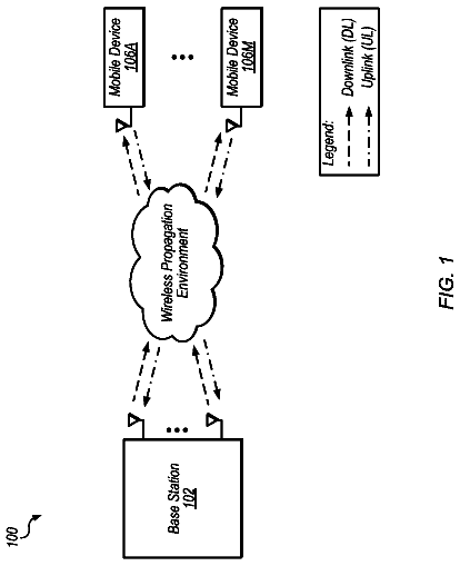
1 of 16 drawing sheets so far from the published document, cropped to the drawing. Every sheet is in the USPTO PDF.
What the patent claimed, word for word. All of it is now free to use.
The disclosed embodiments relate generally to memory systems, and in particular, to encoding and decoding data, modifying error correction parameters, and performing sequential read and write memory operations.
Non-volatile memories, such as flash memory devices, have supported the increased portability of consumer electronics, and have been utilized in relatively low power enterprise storage systems suitable for cloud computing and mass storage. The ever-present demand for almost continual advancement in these areas is often accompanied by demand to improve data storage capacity. The demand for greater storage capacity in turn stokes demand for greater storage density, so that specifications such as power consumption and form factor may be maintained and preferably reduced. As such, there is ongoing pressure to increase the storage density of non-volatile memories in order to further improve the useful attributes of such devices. However, a drawback of increasing storage density is that the stored data is increasingly prone to storage and/or reading errors.
Error correction schemes have been used to limit the increased likelihood of errors in memory systems. However, error correction schemes, particularly those with high error correction capability, are often resource intensive and not configured for optimal system performance.
Various implementations of systems, methods and devices within the scope of the appended claims each have several aspects, no single one of which is solely responsible for the attributes described herein. Without limiting the scope of the appended claims, after considering this disclosure, and particularly after considering the section entitled “Detailed Description” one will understand how the aspects of various implementations are used to enable: (i) encoding and decoding data in accordance with an error correction format of a respective memory portion of non-volatile memory, (ii) modifying an error correction format of a respective memory portion of non-volatile memory, and (iii) reading data stored in a non-volatile storage device having a plurality of physical memory portions having a predefined sequence of physical locations in one or more non-volatile memory.
In one aspect, encoding and decoding data to be stored in a memory portion of non-volatile memory is in accordance with a respective error correction format. In particular, the respective error correction format corresponds to a code rate, a codeword structure, and an error correction type. Furthermore, the respective error correction format comprises one of a sequence of three or more predefined error correction formats, wherein a plurality of the sequence of predefined error correction formats have a same number of error correction bits and different numbers of data bits.
In another aspect, a respective error correction format of a memory portion of non-volatile memory is modified. In particular, a performance metric of the respective memory portion is measured or otherwise obtained, and the respective error correction format is modified in accordance with the obtained performance metric of the respective memory portion, where the error correction format corresponds to a code rate, a codeword structure, and an error correction type. Furthermore, in accordance with the modified error correction format, data is stored in the respective memory portion, and errors are detected and corrected in the data stored in the respective memory portion.
In yet another aspect, data stored in a non-volatile storage device having a plurality of physical memory portions having a predefined sequence of physical locations in one or more non-volatile memory devices is read. In particular, a command for reading a requested logical group of data having a specified logical address is executed, which includes mapping the logical address to one or more physical locations in the storage device. In accordance with a determination that the one or more physical locations in the storage device correspond to two physical memory portions at sequential physical locations in the predefined sequence of physical locations, a single sequential read operation is used to read data from the two physical memory portions, after which the requested logical group of data is returned.
So that the present disclosure can be understood in greater detail, a more particular description may be had by reference to the features of various implementations, some of which are illustrated in the appended drawings. The appended drawings, however, merely illustrate the more pertinent features of the present disclosure and are therefore not to be considered limiting, for the description may admit to other effective features.
FIG. 1 is a block diagram illustrating an implementation of a data storage system, in accordance with some embodiments.
FIG. 2 is a block diagram illustrating an implementation of a management module, in accordance with some embodiments.
FIG. 3 illustrates codewords produced in accordance with various error correction formats, in accordance with some embodiments.
FIGS. 4A-4B illustrates various tables for defining and storing error correction format information, in accordance with some embodiments.
FIGS. 5A-5B are prophetic illustrations of performance metrics for memory portions of a storage device, in accordance with some embodiments.
FIG. 6 represents physical and logical views of data in a storage device, in accordance with some embodiments.
FIGS. 7A-7C illustrate a flowchart representation of a method of encoding and decoding data for a plurality of memory portions of a non-volatile memory device, in accordance with some embodiments.
FIGS. 8A-8C illustrate a flowchart representation of a method of modifying an error correction format of a respective memory portion of a non-volatile memory device, in accordance with some embodiments.
FIGS. 9A-9C illustrates a flowchart representation of a method for reading data stored in a non-volatile memory device, in accordance with some embodiments.
In accordance with common practice the various features illustrated in the drawings may not be drawn to scale. Accordingly, the dimensions of the various features may be arbitrarily expanded or reduced for clarity. In addition, some of the drawings may not depict all of the components of a given system, method or device. Finally, like reference numerals may be used to denote like features throughout the specification and figures.
The various implementations described herein include systems, methods and/or devices used to enable: (i) encoding and decoding data in accordance with an error correction format of a respective memory portion of non-volatile memory, (ii) modifying an error correction format of a respective memory portion of non-volatile memory, and (iii) reading data stored in a non-volatile storage device having a plurality of physical memory portions having a predefined sequence of physical locations in one or more non-volatile memory.
(A1) More specifically, some implementations include a method of encoding and decoding data for a plurality of memory portions of a non-volatile memory device. In some implementations, the method includes, for each respective memory portion of the plurality of distinct memory portions of the NVM, in accordance with an error correction format of the respective memory portion: encoding data to produce one or more codewords; storing the one or more codewords in the respective memory portion; and decoding the one or more codewords to produce decoded data corresponding to the encoded data one or more codewords, which includes detecting and correcting errors in the decoded data. Each memory portion of the plurality of memory portions of the NVM has a corresponding error correction format, the error correction format corresponding to a code rate, a codeword structure, and an error correction type. Furthermore, the error correction format comprises one of a sequence of three or more predefined error correction formats, wherein a plurality of the sequence of predefined error correction formats have a same number of error correction bits and different numbers of data bits. Moreover, at least two memory portions of the plurality of memory portions of the NVM have distinct error correction formats.
(A2) In some embodiments of the method of A1, each error correction format in the sequence of predefined error correction formats has a corresponding error correction format index value in a sequence of error correction format index values.
(A3) In some embodiments of the method of A2, the method includes storing, in a table, the corresponding error correction format index values of two or more memory portions of the plurality of memory portions of the NVM.
(A4) In some embodiments of the method of A3, the method includes, for a respective memory portion of the plurality of memory portions of the NVM: obtaining a performance metric of the respective memory portion; modifying the error correction format of the respective memory portion in accordance with the obtained performance metric; and recording, in the table, an error correction format index value corresponding to the modified error correction format.
(A5) In some embodiments of the method of any of A1-A4, the plurality of distinct memory portions of non-volatile memory (NVM) in the storage device includes a plurality of distinct memory portions of non-volatile memory (NVM) in each of a plurality of non-volatile memory die. The method includes storing, in one or more tables, a base correction format index value for each non-volatile memory die of the plurality of non-volatile memory die, the base correction format index value for a respective non-volatile memory die indicating a default error correction format for memory portions in the non-volatile memory die. Furthermore, the method includes storing, in one or more tables, a plurality of exception values, each exception value indicating, for a corresponding memory portion of a particular non-volatile memory die of the plurality of non-volatile memory die, an error correction format distinct from the default error correction format for memory portions in the particular non-volatile memory die.
(A6) In some embodiments of the method of any of A1-A5, each predefined error correction format in the sequence of predefined error correction formats corresponds to a distinct combination of code rate and error correction type.
(A7) In some embodiments of the method of any of A1-A6, the error correction format of two or more memory portions of the plurality of memory portions is a base error correction format selected in accordance with physical characteristics of the two or more memory portions.
(A8) In some embodiments of the method of A7, the physical characteristics include a physical location of the respective memory portion, wherein the physical location corresponds to either an upper page or a lower page of a multi-level cell.
(A9) In some embodiments of the method of any of A1-A8, the distinct memory portions are distinct memory erase blocks, word lines or pages of the NVM.
(A10) In another aspect, any of the methods A1-A9 described above are performed by a data storage device or system comprising non-volatile memory (NVM) having a plurality of distinct memory portions, wherein each memory portion of at least a subset of the plurality of memory portions of the NVM has a corresponding error correction format. Furthermore, the error correction format corresponds to a code rate, a codeword structure, and an error correction type, and the error correction format comprises one of a sequence of three or more predefined error correction formats, wherein a plurality of the sequence of predefined error correction formats have a same number of error correction bits and different numbers of data bits. Each error correction format in the sequence of predefined error correction formats has a corresponding error correction format index value in a sequence of error correction format index values, and at least two memory portions of at least the subset of the memory portions have distinct error correction formats. The storage device or system further includes an encoder to produce, in accordance with an error correction format of a respective memory portion, one or more codewords from data for storage in the respective memory portion, and a decoder to produce, in accordance with an error correction format of a respective memory portion, decoded data from one or more codewords, and to detect and correct errors in the decoded data.
(A11) In yet another aspect, a non-transitory computer readable storage medium stores one or more programs for execution by one or more processors, the one or more programs including instructions for performing the method of any of A1 to A8.
(B1) Some implementations include a method of modifying an error correction format of a respective memory portion of non-volatile memory (NVM) in a storage device. In some implementations, the method includes, for each respective memory portion of a plurality of distinct memory portions of the NVM: obtaining a performance metric of the respective memory portion; and modifying a current error correction format of the respective memory portion in accordance with the obtained performance metric, wherein the current error correction format corresponds to a code rate, a codeword structure, and an error correction type. Furthermore, the method includes, for each respective memory portion of a plurality of distinct memory portions of the NVM: storing data in the respective memory portion in accordance with the modified error correction format; and detecting and correcting errors in the data stored in the respective memory portion in accordance with the modified error correction format of the respective memory portion. The modified error correction format is distinct from the current error correction format, and the modified error correction format and the current error correction format comprise two of a sequence of three or more predefined error correction formats, wherein a plurality of the sequence of predefined error correction formats have a same number of error correction bits and different numbers of data bits.
(B2) In some embodiments of the method of B1, modifying the current error correction format of the respective memory portion includes modifying at least one of the code rate and the error correction type corresponding to the current error correction format.
(B3) In some embodiments of the method of B1, modifying the current error correction format of the respective memory portion includes modifying at least one of the codeword structure and the error correction type corresponding to the current error correction format.
(B4) In some embodiments of the method of any of B1-B3, each predefined error correction format in the sequence of predefined error correction formats corresponds to a distinct combination of code rate and error correction type.
(B5) In some embodiments of the method of any of B3-B4, each error correction format in the sequence of predefined error correction formats has a corresponding error correction format index value in a sequence of error correction format index values. Furthermore, modifying the current error correction format of the respective memory portion includes: decreasing an error correction format index for the respective memory portion to an index value for an error correction format preceding the current error correction format in the sequence of predefined error correction formats; or increasing the error correction format index for the respective memory portion to an index value for an error correction format succeeding the current error correction format in the sequence of predefined error correction formats.
(B6) In some embodiments of the method of B5, decreasing the error correction format index is in accordance with a determination that the performance metric of the respective memory portion satisfies (e.g., is less than) a first threshold performance metric, and increasing the error correction format index is in accordance with a determination that the performance metric of the respective memory portion satisfies (e.g., is greater than) a second threshold performance metric, wherein the second threshold performance metric is greater than the first threshold performance metric.
(B7) In some embodiments of the method of B6, the method includes, in accordance with a determination that the performance metric of the respective memory portion satisfies (e.g., is greater than) a third threshold performance metric, detecting and correcting errors in data stored in the respective memory portion using soft information, wherein the third threshold performance metric is greater than the second threshold performance metric.
(B8) In some embodiments of the method of any of B1-B7, the current error correction format of the respective memory portion is a base error correction format selected in accordance with physical characteristics of the respective memory portion.
(B9) In some embodiments of the method of B8, the physical characteristics include a physical location of the respective memory portion, wherein the physical location corresponds to either an upper page or a lower page of a multi-level cell.
(B10) Furthermore, in some embodiments of the method of any of B1-B9, the method includes modifying the current error correction format of the respective memory portion in accordance with a change in the physical characteristics of the respective memory portion.
(B11) In some embodiments of the method of any of B1-B10, modifying the current error correction format of the respective memory portion includes recording, in an exception table in the storage device, a value corresponding to the modified error correction format.
(B12) In some embodiments of the method of any of B1-B11, modifying the current error correction format is performed in accordance with detection of a predefined trigger condition.
(B13) In some embodiments of the method of any of B1-B12, the distinct memory portions are distinct memory erase blocks, word lines or pages of the NVM device.
(B14) In some embodiments, the performance metric is a bit error rate (BER).
(B15) In another aspect, any of the methods B1-B14 are performed by a storage device or system that includes non-volatile memory (NVM) having a plurality of distinct memory portions in a plurality of non-volatile memory (NVM) devices, and one or more memory controllers, the one or more memory controllers including one or more processors and memory for storing one or more programs for execution by the one or more processors, the one or more programs including instructions for performing the method of any of B1-B14.
(B16) In some embodiments of the storage device or system of B15, the storage device or system includes a performance metric module configured to obtain a performance metric of a respective memory portion in the plurality of NVM devices; an ECC adjustment module configured to modify a current error correction format of the respective memory portion in accordance with the obtained performance metric, and record, in a table in the storage device or system, an error correction format index value corresponding to the modified error correction format.
(B17) In some embodiments of the storage device or system of B15, the storage device or system includes a performance metric module configured to obtain a performance metric of a respective memory portion in the plurality of NVM devices, an ECC adjustment module configured to modify a current error correction format of the respective memory portion in accordance with the obtained performance metric, and a memory operation module configured to store data in the respective memory portion, and to detect and correct errors in the data stored in the respective memory portion.
(B16) In yet another aspect, a non-transitory computer readable storage medium stores one or more programs for execution by one or more processors (e.g., in one or more storage controllers of a storage device or system), the one or more programs including instructions for performing the method of any of B1 to B14.
(C1) Some implementations include a method of reading data stored in a non-volatile storage device having a plurality of physical memory portions having a predefined sequence of physical locations in one or more non-volatile memory devices of the storage device. In some implementations, the method includes, executing a command for reading a requested logical group of data having a specified logical address, including mapping the logical address to one or more physical locations in the storage device. Furthermore, in accordance with a first determination that the one or more physical locations in the storage device correspond to a single physical memory portion, data is read from the single physical memory portion, which includes the requested logical group of data, and the requested logical group of data is returned. In accordance with a second determination that the one or more physical locations in the storage device correspond to two physical memory portions at sequential physical locations in the predefined sequence of physical locations, a single sequential read operation is used to read data from the two physical memory portions, which together include the requested logical group of data, and the requested logical group of data is returned. In accordance with a third determination that the one or more physical locations in the storage device correspond to two physical memory portions at non-sequential physical locations in the predefined sequence of physical locations, two read operations are used to read data from the two non-sequential physical memory portions, which together include the requested logical group of data, and the requested logical group of data is returned.
(C2) In some embodiments of the method of C1, in accordance with the second determination, the single sequential read operation to read data from the two physical memory portions reads data from a single word line of a respective NVM device of the storage device.
(C3) In some embodiments of the method of C1 or C2, in accordance with the third determination, the two read operations to read data from the two non-sequential physical memory portions read data from two distinct word lines in one or two NVM devices of the storage device.
(C4) In some embodiments of the method of any of C1-C3, in accordance with the first determination, reading data from the single physical memory portion includes reading data from a plurality of codewords.
(C5) Furthermore, in some embodiments of the method of C4, the plurality of codewords includes data for at least one logical group of data other than the requested logical group of data.
(C6) In some embodiments of the method of any of C1 to C5, the physical memory portions are physical pages of the NVM device, and the requested logical group of data comprises a logical page of data.
(C7) In some embodiments of the method of any of C1 to C6, the sequential read operation reads data from a plurality of physical memory portions, wherein the plurality of physical memory portions store a plurality of logical groups of data.
(C8) In some embodiments of the method of any of C1 to C7, in accordance with the second determination, reading data from the two physical memory portions includes: reading data from a first plurality of codewords stored in one of the two physical memory portions; and reading data from a second plurality of codewords stored in the other of the two physical memory portions, wherein each codeword of the first plurality of codewords have a first codeword length, and each codeword of the second plurality of codewords have a second codeword length, distinct from the first codeword length.
(D1) Some implementations include a method of storing data in a non-volatile storage device having a plurality of physical memory portions, the physical memory portions having a predefined sequence of physical locations in one or more non-volatile memory devices of the storage device. In some implementations, the method includes executing a plurality of commands, each command of the plurality of commands for storing in the storage device a requested logical group of data having a specified logical address. Executing a plurality of commands includes, for each command of the plurality of commands, storing the data in one or more physical locations in the storage device. Furthermore, executing a plurality of commands includes, for each command of the plurality of commands, mapping the logical address of the logical group of data to the one or more physical locations in the storage device. Specifically, for a first command of the plurality of commands, the one or more physical locations in the storage device correspond to a single physical memory portion in the storage device. For a second command of the plurality of commands, the one or more physical locations in the storage device correspond to two physical memory portions at sequential physical locations in the predefined sequence of physical locations. Furthermore, for a third command of the plurality of commands, the one or more physical locations in the storage device comprise two physical memory portions at non-sequential physical locations in the predefined sequence of physical locations.
(D2) In some embodiments of the method of D1, for the first command, a first physical location of the one or more physical locations meets first criteria. Furthermore, for the second command, the first physical location of the one or more physical locations meets second criteria distinct from the first criteria. Moreover, for the third command, the first physical location of the one or more physical locations meets third criteria distinct from the first criteria and second criteria.
(D3) In some embodiments of the method of D1 or D2, the third criteria is met by a respective starting point physical location when the first and second criteria are not met.
(D4) In some embodiments of the method of any of D1 to D4, storing the data in the one or more physical locations in the storage device includes: encoding the data to produce one or more codewords, and storing the one or more codewords in the one or more physical locations in the storage device.
(D5) In some embodiments of the method of any of D1 to D4, the two physical memory portions at sequential physical locations in the predefined sequence of physical locations are physical memory portions of a single word line of a respective NVM device of the storage device.
(D6) In some embodiments of the method of any of D1 to D5, the two physical memory portions at non-sequential physical locations in the predefined sequence of physical locations are physical memory portions of two distinct word lines in one or two NVM devices of the storage device.
(D7) In another aspect, any of the methods C1 to C8 and D1 to D6 described above are performed by a storage device comprising:
one or more non-volatile memory devices;
a memory controller that includes a mapping module; and
an interface to receive a plurality of commands. Each command of the plurality of commands comprising a command to access one or more physical locations in the storage device in accordance with a specified logical address specified by the command. Furthermore, the mapping module is configured to map the specified logical address, specified by a respective command of the plurality of commands, to the one or more physical locations in the one or more non-volatile memory devices of the storage device, wherein: for a first command of the plurality of commands, the one or more physical locations in the storage device correspond to a single physical memory in the storage device; for a second command of the plurality of commands, the one or more physical locations in the storage device correspond to two physical memory portions at sequential physical locations in the predefined sequence of physical locations; and for a third command of the plurality of commands, the one or more physical locations in the storage device comprise two physical memory portions at non-sequential physical locations in the predefined sequence of physical locations.
(D8) In yet another aspect, a non-transitory computer readable storage medium stores one or more programs for execution by one or more processors, the one or more programs including instructions for performing the method of any of C1 to C8 and D1 to D6.
(E1) Some embodiments include an electronic system or device (e.g., data storage device 120 , data storage system 100 , or storage controller 124 , FIG. 1 ), comprising: one or more processors; and memory storing one or more programs to be executed by the one or more processors, the one or more programs comprising instructions for performing or controlling performance of any of the methods described herein. Some embodiments include a non-transitory computer readable storage medium, storing one or more programs for execution by one or more processors of an electronic system or device (e.g., data storage device 120 , FIG. 1 or storage controller 124 , FIG. 1 ), the one or more programs including instructions for performing or controlling performance of any of the methods described herein. Some embodiments include an electronic system or device (e.g., data storage device 120 , FIG. 1 or storage controller 124 , FIG. 1 ) comprising means for performing or controlling performance of the operations of any of the methods described herein.
Numerous details are described herein in order to provide a thorough understanding of the example implementations illustrated in the accompanying drawings. However, some embodiments may be practiced without many of the specific details, and the scope of the claims is only limited by those features and aspects specifically recited in the claims. Furthermore, well-known methods, components, and circuits have not been described in exhaustive detail so as not to unnecessarily obscure more pertinent aspects of the implementations described herein.
FIG. 1 is a block diagram illustrating an implementation of a data storage system 100 , in accordance with some embodiments. While some example features are illustrated, various other features have not been illustrated for the sake of brevity and so as not to obscure pertinent aspects of the example embodiments disclosed herein. To that end, as a non-limiting example, data storage system 100 includes a storage device 120 , which includes a storage controller 124 and one or more memory channels 150 that each include one or more NVM devices 140 and optionally include a respective NVM controller 130 , where data storage system 100 is used in conjunction with or includes a computer system 110 . In some embodiments, NVM devices 140 for a single memory channel 150 comprise a single flash memory device while in other embodiments NVM devices 140 for a single memory channel 150 include a plurality of flash memory devices. In some embodiments, NVM devices 140 are NAND-type flash memory or NOR-type flash memory. In some embodiments, NVM devices 140 include one or more three-dimensional (3D) memory devices, as further defined herein. Further, in some embodiments, storage controller 124 is a solid-state drive (SSD) controller. However, other types of storage media may be included in accordance with aspects of a wide variety of embodiments (e.g., PCRAM, ReRAM, STT-RAM, etc.). In some embodiments, a flash memory device includes one or more flash memory die, one or more flash memory packages, one or more flash memory channels or the like. In some embodiments, data storage system 100 can contain one or more storage devices 120 .
Computer system 110 is coupled to storage controller 124 through data connections 101 , and optionally through a control bus or connection 111 as well. However, in some embodiments computer system 110 includes storage controller 124 , or a portion of storage controller 124 , as a component and/or a subsystem. For example, in some embodiments, some or all of the functionality of storage controller 124 is implemented by software executed on computer system 110 . Computer system 110 may be any suitable computer device, such as a computer, a laptop computer, a tablet device, a netbook, an internet kiosk, a personal digital assistant, a mobile phone, a smart phone, a gaming device, a computer server, or any other computing device. Computer system 110 is sometimes called a host, host system, client, or client system. In some embodiments, computer system 110 is a server system, such as a server system in a data center. In some embodiments, computer system 110 includes one or more processors, one or more types of memory, a display and/or other user interface components such as a keyboard, a touch screen display, a mouse, a track-pad, a digital camera and/or any number of supplemental devices to add functionality. In some embodiments, computer system 110 does not have a display and other user interface components.
In some implementations, storage device 120 includes NVM devices 140 such as flash memory devices (e.g., NVM devices 140 - 1 through 140 - n ). The NVM devices of storage device 120 are sometimes collectively called a storage medium. In some embodiments storage device 120 includes NVM controllers (e.g., NVM controllers 130 , sometimes called memory channel controllers or port controllers) coupled between storage controller 124 and NVM devices 140 . Viewed another way, in the aforementioned embodiments, storage device 120 includes m memory channels (e.g., memory channels 150 - 1 through 150 - m ), each of which has an NVM controller 130 and a set of NVM devices 140 coupled to the NVM controller for that memory channel, where m is an integer greater than one. However, in some embodiments, two or more memory channels share an NVM controller. Typically, each memory channel 150 has its own distinct set of one or more NVM devices 140 . Alternatively, in some embodiments, storage device 120 does not include any NVM controllers 130 , and instead storage controller 124 handles functions such as host command parsing and logical to physical address translation, and also manages the NVM devices 140 in all the memory channels 150 - 1 to 150 - m , including distributing individual memory operations (e.g. read, write, and erase) commands to the NVM devices 140 in the various memory channels. In a non-limiting example, the number of memory channels in a typical storage device is 8, 16 or 32. In another non-limiting example, the number of NVM devices 140 per memory channel is typically 8, 16, 32 or 64. Furthermore, in some implementations, the number of NVM devices 140 is different in different memory channels.
Memory channels 150 are coupled to storage controller 124 through connections 103 . Connections 103 are sometimes called data connections, but typically convey commands in addition to data, and optionally convey metadata, error correction information and/or other information in addition to data values to be stored in NVM devices 140 and data values read from NVM devices 140 . In some embodiments, however, storage controller 124 and NVM devices 140 are included in the same device (i.e., an integral device) as components thereof. Furthermore, in some embodiments, storage controller 124 and NVM devices 140 are embedded in a host device (e.g., computer system 110 ), such as a mobile device, tablet, other computer or computer controlled device, and the methods described herein are performed, at least in part, by the embedded memory controller.
Flash memory device(s) (e.g., NVM devices 140 ) can be configured for enterprise storage suitable for applications such as cloud computing, for database applications, primary and/or secondary storage, or for caching data stored (or to be stored) in secondary storage, such as hard disk drives. Additionally and/or alternatively, flash memory device(s) can also be configured for relatively smaller-scale applications such as personal flash drives or hard-disk replacements for personal, laptop, and tablet computers.
NVM devices 140 are divided into a number of addressable and individually selectable blocks. In some embodiments, the individually selectable blocks are the minimum size erasable units in a flash memory device. In other words, each block contains the minimum number of memory cells that can be erased simultaneously. Each block is usually further divided into a plurality of pages and/or word lines, where each page or word line is typically an instance of the smallest individually accessible (readable) portion in a block. In some embodiments (e.g., using some types of flash memory), the smallest individually accessible unit of a data set, however, is a sector, which is a subunit of a page. That is, a block includes a plurality of pages, each page contains a plurality of sectors, and each sector is the minimum unit of data for reading data from the flash memory device. The number of pages included in each block varies from one implementation to another; examples are 64, 128 and 256 pages, but other numbers of pages per block are suitable in some implementations.
As noted above, while data storage densities of non-volatile semiconductor memory devices are generally increasing, a drawback of increasing storage density is that the stored data is more prone to being stored and/or read erroneously. In some embodiments, error control coding can be utilized to limit the number of uncorrectable errors that are introduced by electrical fluctuations, defects in the storage medium, operating conditions, device history, write-read circuitry, etc., or a combination of these and various other factors.
In some embodiments, storage controller 124 includes a management module 121 , a host interface 129 , a storage medium I/O interface 128 , and error control module 125 . Storage controller 124 may include various additional features that have not been illustrated for the sake of brevity and so as not to obscure pertinent features of the example embodiments disclosed herein, and a different arrangement of features may be possible. Host interface 129 provides an interface to computer system 110 through data connections 101 . Similarly, storage medium I/O 128 provides an interface to memory channels 150 and respective NVM devices 140 though connections 103 . In some embodiments, storage medium I/O 128 includes transmit and receive circuitry, including circuitry capable of providing reading signals to NVM controllers 130 (e.g., reading threshold voltages for NAND-type flash memory).
In some embodiments, management module 121 includes one or more processing units (CPUs, also sometimes called processors) 122 configured to execute instructions in one or more programs (e.g., in management module 121 ). In some embodiments, the one or more CPUs 122 are shared by one or more components within, and in some cases, beyond the function of storage controller 124 . Management module 121 is coupled to host interface 129 , error control module 125 and storage medium I/O 128 in order to coordinate the operation of these components. In some embodiments, one or more modules of management module 121 are implemented in a management module of computer system 110 (not shown). In some embodiments, one or more processors of computer system 110 (not shown) are configured to execute instructions in one or more programs (e.g., in a management module of computer system 110 ).
The description continues in the full USPTO document.
About 6,280 words. The USPTO PDF has it with every drawing.
Fees are due 3.5, 7.5 and 11.5 years after grant. This patent expired on September 19, 2025, so the fee marked "not paid" was the one that went unpaid.
Method for Modifying Device-Specific Variable Error Correction Settings
Filed Oct 2015 · published Oct 2016Method for modifying device-specific variable error correction settings
Filed Oct 2015 · granted Sep 2017Earlier publications, parents and continuations. None of them can still be enforced, or this patent would not be listed.
Prior art cited by the examiner or applicant. Useful when you check your own idea for novelty.
Everything on this page comes from the documents linked above.