This application is a section 371 of PCT/EP2014/053817 filed 2014 Feb. 27.
Field of the invention
The invention relates to a single-phase electric motor.
Background
In three-phase motors having a stator and a rotor, the ratio between stator poles and rotor poles is always unequal. For example, a three-phase motor having six stator poles that are arranged at a spacing of 60° from one another, and has four rotor poles that are arranged at a spacing of 90° from one another. Each of the three phases here has two mutually oppositely located stator poles associated with it. The result is that, in any rotor position, it is possible to generate a torque via at least two of the three phases, since a magnetically different position of the rotor poles is located opposite each of the three phases. It is thus possible to start the motor with high torque in any rotor position.
With single-phase motors, the number of rotor poles corresponds to the number of stator poles. The consequence of this is that whenever each rotor pole is located opposite exactly one stator pole, no torque can be generated by a flow of current through the winding arrangement. In addition, for example in fans, the rotor preferentially assumes precisely that position when stopped, since it corresponds to the lowest-energy state.
Several methods are already known for enabling starting of such a motor, despite this. DE 8 702 271 U1, corresponding to SCHIMIDER U.S. Pat. No. 5,109,171, describes an electric motor in which soft magnetic iron plates are mounted on the rotor in such a way that in the zero-current-flow state, it assumes a position from which starting is possible. This is also referred to as generating an “auxiliary reluctance torque.”
DE 3 149 766 A1, corresponding to MUELLER U.S. Pat. No. 4,730,136, describes an electric motor in which the stator poles are implemented asymmetrically, so that the spacing between the stator poles and the rotor decreases as viewed in a circumferential direction. The rotor poles of the rotor magnet preferentially assume a position in which they are on average as close as possible to the stator pole. This once again results, in the zero-current-flow state, in a starting position from which the motor can begin to operate.
Millions of such motors are used in CD players and hard drives.
The aforesaid approaches require a motor in which the external torque and the friction that occur are not too great, as is the case e.g. with fans. Otherwise there is no guarantee that the starting position can reliably be assumed. The area of application for these approaches is thus limited.
Summary of the invention
An object of the invention is to furnish a novel single-phase motor.
The object is achieved by an electric motor that comprises: a stator having a number S of stator poles, a rotor having a rotor magnet, which rotor magnet has a number R of rotor poles, R being equal to S, and the rotor or the stator or both exhibiting an asymmetry; a single-phase winding arrangement having a first winding terminal and a second winding terminal, current being capable of flowing through a number W of coils of the winding arrangement via the first winding terminal and the second winding terminal; an output stage that is implemented to enable a current between the first winding terminal and the second winding terminal; a first apparatus that is implemented to enable, in interaction with the output stage, a current flow through at least one sub-group of the W coils, the at least one sub-group encompassing more than none of the W coils and fewer than W of the W coils.
The asymmetry is preferably implemented to make possible, at any rotor position of the rotor, the generation of a torque via at least one of the following current-flow processes:
current flow through all W coils, or
current flow through the at least one sub-group of the coils.
Preferably at least two sub-groups are provided.
Preferably the first apparatus comprises a third winding terminal and a switch in order to enable a current between the first winding terminal or the second winding terminal on the one hand, and the third winding terminal on the other hand.
Preferably the number of coils between the first winding terminal and the third winding terminal is not equal to the number of coils between the third winding terminal and the second winding terminal.
Preferably the winding arrangement comprises a plurality of mutually parallel sub-strands, and the first apparatus comprises a switch that is implemented, in the nonconducting state, to prevent a current through a first portion of the sub-strands but not to prevent a current through the remaining sub-strands.
Preferably the rotor exhibits an asymmetry that is generated by the fact that the R rotor poles have, at least in part, an angular extent different from one another.
Preferably the rotor exhibits an asymmetry that is generated by the fact that the angular distance of the magnetic center of one rotor pole from the magnetic center of an adjacent rotor pole is, at least in part, not equal to 360°/R.
Preferably the rotor exhibits an asymmetry that is generated by an asymmetrical magnetization of the rotor magnet.
Preferably the rotor exhibits an asymmetry that is achieved by an asymmetrical arrangement of different materials in the region of the rotor, the different materials having different magnetic properties.
Preferably the stator exhibits an asymmetry that is generated by the fact that the angular distance of the adjacent stator poles is, at least in part, not equal to 360°/S, where preferably S=2.
Preferably the at least one sub-group encompasses at least one of the W coils and at most W−1 coils.
Preferably W=S.
Preferably the output stage comprises a full bridge circuit in order to enable a current flow through the winding arrangement between the first winding terminal and the second winding terminal in both directions.
Preferably the rotor magnet comprises permanent-magnet rotor poles or electromagnetically generated rotor poles; in the case of the electromagnetically generated rotor poles, each rotor pole having, associated with it, a winding through which current flows during operation.
The object is achieved by a method for current flow through an electric motor having a stator having S stator poles, a rotor having R rotor poles, R being equal to S; having a single-phase winding arrangement having a first winding terminal and a second winding terminal, W coils being electrically connected between the first winding terminal and the second winding terminal; having an output stage that is implemented to enable a current between the first winding terminal and the second winding terminal; having a first apparatus that is implemented to enable, in interaction with the output stage, a current flow through at least one sub-group of the W coils, the at least one sub-group encompassing more than none of the W coils and fewer than W of the W coils; which method comprises the following steps:
A) with the electric motor in a first state, the output stage is controlled in such a way that current flows through all W coils via the first winding terminal and the second winding terminal;
B) with the electric motor in a second state, the output stage is controlled in such a way that current flows through only the at least one sub-group of the W coils.
Preferably the rotation speed of the electric motor is sensed, and a switchover occurs from the first state of the electric motor into the second state when the rotation speed of the electric motor is below a predetermined minimum rotation speed.
Preferably a switchover into the second state occurs upon starting of the motor, and then a switchover into the first state occurs.
Preferably in the first state the direction of the current flow between the first winding terminal and the second winding terminal is predetermined as a function of the rotor position of the rotor.
Further details and advantageous refinements of the invention are evident from the exemplifying embodiments, in no way to be understood as a limitation of the invention, that are described below and depicted in the drawings.
Brief figure description
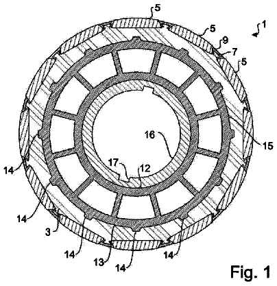
FIG. 1 schematically depicts a single-phase electric motor 10 having six stator poles;
FIG. 2 is a circuit diagram of a circuit for operating motor 10 of FIG. 1 ;
FIG. 3 shows a measurement of the induced voltage of motor 10 of FIG. 1 ;
FIG. 4 is a detail view of FIG. 3 ;
FIG. 5 shows an output stage for motor 10 of FIG. 1 having two coils;
FIG. 6 shows an output stage for motor 10 of FIG. 1 having two coils;
FIG. 7 shows an output stage for motor 10 of FIG. 1 having two coils;
FIG. 8 shows an output stage for motor 10 of FIG. 1 having two strands;
FIG. 9 shows an output stage for motor 10 of FIG. 1 having four coils that are connected in series;
FIG. 10 shows an output stage for motor 10 of FIG. 1 having four coils that are connected in series;
FIG. 11 shows an output stage for motor 10 of FIG. 1 having four coils that are connected in parallel in two arms;
FIG. 12 shows an output stage for motor 10 of FIG. 1 having four coils that are connected in parallel in two arms;
FIG. 13 shows a four-pole rotor of motor 10 of FIG. 1 in which the rotor poles have two different angular extents;
FIG. 14 shows a four-pole rotor of motor 10 of FIG. 1 in which the rotor poles have three different angular extents;
FIG. 15 shows a four-pole rotor 40 in which neutral regions having different angular extents are provided between the rotor poles;
FIG. 16 shows a rotor 40 for motor 10 of FIG. 1 having oblique rotor poles;
FIG. 17 shows an asymmetrical six-pole stator for motor 10 of FIG. 1 ;
FIG. 18 shows an asymmetrical two-pole stator for motor 10 of FIG. 1 ;
FIG. 19 shows comparative measurements of the voltage constant kE;
FIG. 20 shows comparative measurements of the cogging torque;
FIG. 21 shows comparative measurements of the voltage constant kE;
FIG. 22 shows comparative measurements of the cogging torque;
FIG. 23 shows a measurement of the current through the output stage of motor 10 of FIG. 1 with no correction of the rotor position signal;
FIG. 24 shows a measurement of the current through the output stage of motor 10 of FIG. 1 with an improved rotor position signal;
FIG. 25 shows a variant winding pattern of a six-pole stator of motor 10 of FIG. 1 ;
FIG. 26 shows an output stage for motor 10 of FIG. 1 having a winding terminal in the region of a coil;
FIG. 27 is a flow chart for a method for starting motor 10 of FIG. 1 ; and
FIG. 28 shows an electromagnetically generated rotor magnet.
Detailed description
FIG. 1 shows an electric motor 10 having a stator 20 and a rotor 40 . Stator 20 has a winding arrangement 30 associated with it, and it has six stator poles 21 to 26 . Rotor 40 has a rotor magnet 40 ′ likewise having six rotor poles 41 to 46 that are preferably implemented as permanent-magnet rotor poles 41 to 46 .
Winding arrangement 30 has six coils 31 to 36 , connected in series, that are connected or electrically joined in series between a first winding terminal 11 and a second winding terminal 12 . Each stator pole 21 to 26 has one of coils 31 to 36 associated with it; coils 31 to 36 are wound in such a way that when current flows, a North pole is followed by a South pole, then a North pole again, etc. alternatingly in the respective adjacent stator poles 21 to 26 , since the rotor poles 41 to 46 can also respectively change direction. Winding arrangement 30 begins—proceeding from first winding terminal 11 —at stator pole 21 , proceeds therefrom to stator pole 24 and then to stator poles 25 , 26 , 22 , and 23 , and from there to second winding terminal 12 . Current can thus flow through coils 31 to 36 via first winding terminal 11 and second winding terminal 12 .
A third winding terminal 13 , which can also be referred to as a “tap,” is provided on winding arrangement 30 between stator poles 24 and 25 .
FIG. 2 shows a corresponding circuit diagram for motor 10 of FIG. 1 . It depicts winding arrangement 30 having the six coils 31 to 36 and having first winding terminal 11 , second winding terminal 12 , and third winding terminal 13 , as well as a control apparatus 70 and an output stage 50 for influencing the current through winding arrangement 30 .
A first lead 57 (+U.sub.B) and a second lead 58 (GND or reference potential) are provided in order to deliver a supply voltage +U.sub.B to output stage 50 , for example from a DC voltage source 71 .
A switch 51 is provided between first lead 57 and first winding terminal 11 , and a switch 52 is provided between first winding terminal 11 and second lead 58 .
A switch 53 is provided between first lead 57 and second winding terminal 12 , and a switch 54 is provided between second winding terminal 12 and second lead 58 .
The arrangement having the four switches 51 , 52 , 53 , and 54 is also referred to as a “full bridge circuit” or “H bridge,” in which winding arrangement 30 constitutes the bridge arm of the full bridge circuit.
A switch 56 is provided between third winding terminal 13 and second lead 58 .
Lead 58 is connected via a so-called “base resistor” 60 to a lead 59 , and switches 52 , 54 , 56 are correspondingly connected via lead 59 indirectly to lead 58 . Resistor 60 is usually low-impedance, and it can additionally or alternatively be provided in lead 57 , or can be omitted entirely.
A control apparatus 70 has five control leads 61 , 62 , 63 , 64 , and 66 through which it is connected to the five switches 51 to 54 and 56 in order to render them conductive or non-conductive.
Unless otherwise indicated, switches 51 , 52 , 53 , 54 , 56 , and 55 that are used are preferably controllable switches, more preferably semiconductor switches such as MOSFETs, IGBTs (isolated gate bipolar transistors), or bipolar transistors (see FIG. 6 and FIG. 7 ). Relays, for example, can also be used for switches 55 , 56 .
The upper switches 51 , 53 , 55 are also referred to as “high side” switches, and the lower switches 52 , 54 , 56 as “low side” switches.
Switches 51 to 56 preferably each have a freewheeling diode associated with them (see FIG. 26 ) in order to prevent a current through the switches in the reverse direction, as can occur e.g. as a result of the induced voltage when switches 51 to 56 are non-conductive and rotor 40 is rotating. Alternatively, a freewheeling diode can also be provided only on switches 51 , 52 , 53 , 54 , and switch 56 can be without a freewheeling diode, since the current flow through switch 56 can be limited to the starting operation so that a large induced voltage does not yet occur.
A rotor position sensor 67 (e.g. Hall sensor or magnetoresistive [MR] sensor or encoder) is preferably arranged on rotor 40 , in order to identify the rotor position, and rotor position sensor 67 is connected via a lead 68 to control apparatus 70 .
Control apparatus 70 is connected via a lead 72 to lead 59 in order to measure the potential at base resistor 60 .
Operation
In normal operation, i.e. when rotor 40 is rotating and preferably has reached a minimum rotation speed, current flows through winding arrangement 30 via full bridge circuit 51 , 52 , 53 , 54 .
This is done, for example, by alternatingly either, in a first state Z 1 , rendering switches 51 and 54 conductive or, in a second state Z 2 , rendering switches 53 and 52 conductive.
In the first state Z 1 , a current flows from first lead 57 through switch 51 , winding terminal 11 , winding arrangement 30 , second winding terminal 12 , switch 54 , lead 59 , and base resistor 60 to second lead 58 .
In the second state Z 2 , the current flows from operating voltage 57 through switch 53 , second winding terminal 12 , winding arrangement 30 , first winding terminal 11 , switch 52 , lead 59 , and base resistor 60 to ground 58 .
In the first state Z 1 and second state Z 2 , the remaining switches are non-conductive.
Operation switches back and forth between the first state Z 1 and the second state Z 2 , depending on the rotor position of rotor 40 , so as thereby to drive rotor 40 . The rotor position is sensed via rotor position sensor 67 . Sensing can also occur, however, in sensorless fashion.
The control procedure described above for normal current flow through output stage 50 during operation is an example, and one skilled in the art knows of a plurality of control options for output stages, i.e. including, for example, clock-timed application of control to at least some of switches 51 to 54 , or block commutation.
Base resistor 60 serves to measure the current through output stage 50 so that control apparatus 70 can detect an overcurrent via lead 72 .
Control apparatus 70 controls switches 51 to 53 in order to drive, or optionally also to decelerate, motor 10 . Closed- or open-loop control of rotation speed, power output, etc. is possible here, for example.
Because commutation is effected via switches (here 51 to 54 ) and not via commutator brushes, the motor is also referred to as a “brushless” or “electronically commutated” motor.
Starting the Motor
When motor 10 of FIG. 2 starts, it is possible for rotor 40 to be in an unfavorable rotor position, in which a current flow, through winding arrangement 30 via switches 51 , 54 or 53 , 52 , generates very little or no torque.
Via third winding terminal 13 , it is possible to make switches 51 and 56 conductive in a third state Z 3 , so that a current flows from first lead 57 through switch 51 , first winding terminal 11 , coils 31 and 32 , third winding terminal 13 , switch 56 , lead 59 , base resistor 60 to second lead 58 . Current thus flows through a first sub-group TG 1 of coils 31 to 36 that encompasses only coils 31 and 32 .
It is likewise possible to make switches 53 and 56 conductive in a fourth state Z 4 , so that a current flows from first lead 57 through switch 53 , second winding terminal 12 , coils 36 , 35 , 34 , 33 , third winding terminal 13 , switch 56 , lead 59 , base resistor 60 to second lead 58 . Current thus flows through a second sub-group TG 2 of coils 31 to 36 that encompasses only coils 33 and 36 .
In this exemplifying embodiment, no coils are therefore contained in common in sub-groups TG 1 , TG 2 , but instead current flows through different coils in each case.
The expression for the magnetic (internal) torque M_i of motor 10 is M _ i=k _ mI
where k_m=torque constant (also called “flux linkage”) I=winding current through winding 30
For the actual torque or output torque M, the negatively acting frictional torque M_R must also be taken into account.
The expression for the voltage U_i induced in winding arrangement 30 is U _ i=k _ m omega= k _ m 2 pin/ 60
where omega=ω=angular speed n=rotation speed in min.sup.−1
When the output stage is blocked or output stage transistors 51 , 52 , 53 , 54 , 56 are nonconductive, the voltage U applied to winding terminals 11 , 12 (armature voltage) becomes U=IR+U _ i
where R=resistance of winding arrangement 30 .
The torque constant k_m is a function of the rotor position phi of rotor 40 , i.e. k_m=k_m(phi). The voltage constant kE, which is proportional to k_m and is sometimes also referred to as Ke, is often also considered instead of the torque constant k_m.
As is evident from equations
and (2), the torque constant k_m creates both the proportionality between the torque M_i and the winding current I and the proportionality between the induced voltage U_i and the angular speed omega. It is therefore possible, for example, to ascertain the torque constant k_m by externally driving rotor 40 at a constant angular speed omega and simultaneously measuring the induced voltage U_i, and the profile of the resulting curve is proportional or identical to the curve for the magnetic torque M_i.
FIG. 3 shows a measurement of the induced voltage M_i over one full revolution of rotor 40 from phi=0 to 360°.
Curve 201 shows the induced voltage U_i that is measured between first winding terminal 11 and second terminal 12 . It is apparent that curve 201 has six zero crossings; and if the motor comes to rest in a rotor position at which curve 201 exhibits a zero crossing, then no torque can be generated by a current flow between first winding terminal 11 and second winding terminal 12 .
Curve 202 shows the induced voltage U_i that is induced between first winding terminal 11 and third winding terminal 13 in coils 31 , 32 (sub-group TG 1 ). Curve 202 has a lower amplitude than curve 201 , since what is added is only the signal from the two coils 31 , 32 rather than the signal of all six coils 31 to 36 , as in curve 201 . It is evident that the zero crossings of curve 202 occur at different rotor positions than the zero crossings of curve 201 .
Curve 203 shows the induced voltage U_i that is induced between second winding terminal 12 and third winding terminal 13 in coils 33 to 36 (sub-group TG 2 ). Curve 203 has a lower amplitude than curve 201 and a higher amplitude than curve 202 , since the signal of the four coils 33 to 36 is added. It is evident that the zero crossings of curve 203 occur at different rotor positions than the zero crossings of curves 201 and 202 .
FIG. 4 shows a portion of FIG. 3 for the angle range from 0° to approximately 150°.
Curve 201 , which reproduces the induced voltage U_i between first winding terminal 11 and second winding terminal 12 , has a zero crossing at 60°, the angle of 60° being characterized by vertical line 210 and the zero crossing at 120° being characterized by vertical line 215 . At points 210 and 215 , no torque can be generated by a current flow between winding terminals 11 and 12 because the curve for the torque constant k_m corresponds to the curve for the induced voltage U_i, and both of them have a zero crossing.
Curve 202 , however, has its zero crossing at a point 213 (at approximately 62°) located after point 210 , and at point 210 curve 202 still has a negative value that is characterized as horizontal line 211 .
Curve 203 has its zero crossing before point 210 , at point 214 (at approximately 57°), and at point 210 curve 203 has already risen into the positive region, the value being characterized by a horizontal line 212 .
Because curves 202 , 203 are different from zero at point 210 , a torque can be generated there either via coils 31 , 32 associated with curve 202 (sub-group TG 1 ) or via coils 33 to 36 associated with curve 203 (sub-group TG 2 ).
At point 215 , which corresponds to a rotor position of 120°, curve 202 has already had a zero crossing at a smaller angle (at point 218 ) and has dropped to a negative value that is characterized by a horizontal line 216 .
Curve 203 has its zero crossing just after point 215 at point 219 , and curve 203 is slightly in the positive region at point 215 .
As is evident, the torque achievable via curves 202 , 203 at point 215 is less than at point 210 , and a greater torque can be generated by a current flow through coils 31 , 32 associated with curve 202 than via coils 33 to 36 associated with curve 203 .
At the zero crossings 213 , 218 of curve 202 , the other curves 201 , 203 are respectively positive and negative, and at the zero crossings 214 , 219 of curve 203 the other curves 201 , 202 are respectively positive and negative, i.e. not equal to zero.
The result is that a torque can be generated at any rotor position phi.
Now that the fundamental principle has been presented, details and variants will be discussed below.
Motor Type
The approach presented, with which a torque can be generated at any rotor position, is in principle independent of motor type. Internal-rotor, external-rotor, or disk-armature motors, for example, can be used.
Stator 20 can comprise a stator core as shown, for example, in FIG. 1 , but it can also be configured without a stator core; this is also referred to as an “air-core” winding. The stator core is preferably implemented as a stator stack or stator lamination stack, but other variants are also possible.
The number of S of stator poles 21 , 22 is preferably even, and S=2, 4, 6, 8, . . . or 2*N where N=1, 2, 3, . . . .
The number R of rotor poles 41 , 42 preferably corresponds to the number S of stator poles 21 , 22 , etc.
Rotor 40 is preferably a permanent-magnet rotor 40 having permanent-magnet rotor poles 41 , 42 , etc., or a permanent-magnet rotor magnet 40 ′. It is also possible, however, to use, for example, a motor having electromagnetically generated rotor poles 41 , 42 , etc., in which e.g. each rotor pole 41 , 42 , etc. comprises a winding, depicted in FIG. 28 , through which current flows during operation; current flow occurs as a result of a voltage source 49 , and the winding is wound, for example, around a lamination stack. Voltage source 49 can be arranged on rotor 40 but need not obligatorily be arranged in rotor 40 . In the case of an external arrangement, an electrical connection can be effected e.g. via wiper contacts or other contacts that enable electrical conduction despite the rotational motion of the rotor. Current flows in rotor 40 preferably in such a way that rotor magnets 41 , 42 , etc. always generate a magnetic field in the same direction during operation, so that they can be used like permanent-magnet rotor magnets 41 , 42 , etc.
In the exemplifying embodiment of FIG. 1 , stator 20 has six slots into which the winding arrangement is distributed. This is therefore referred to as a “six-slot” or “six-pole” motor.
Winding Arrangement and Wiring Configuration for Partial Current Flow Through the Coils
FIG. 5 to FIG. 7 and FIG. 26 show a variety of variants for wiring a single-phase, single-strand motor having two poles. The two coils 31 , 32 have first winding terminal 11 and second winding terminal 12 . First winding terminal 11 is connected via switch 51 to first lead 57 , and via switch 52 to second lead 58 . Second winding terminal 12 is connected via switch 53 to first lead 57 and via switch 54 to second lead 58 ; switches 51 to 54 form a full bridge circuit. Third winding terminal 13 is arranged between coils 31 , 32 .
In FIG. 5 , third winding terminal 13 is connected via switch 56 to second lead 58 . With the aid of switch 56 , a current can flow through switch 51 , coil 31 (sub-group TG 1 ), and switch 56 , or a current can flow through switch 53 , coil 32 (sub-group TG 2 ), and switch 56 . The arrangement of switch 56 leading to lead 58 has the advantage that corresponding semiconductor switches and driver circuits are often more inexpensive than for switches that are used between first lead 57 and a winding terminal 11 , 12 , 13 .
In FIG. 6 , third winding terminal 13 is connected via a switch 55 to first lead 57 . With the aid of switch 55 , a current can flow through switch 55 , coil 31 (sub-group TG 1 ), and switch 52 , or a current flows through switch 55 , coil 32 (sub-group TG 2 ), and switch 54 .
In FIG. 7 , third winding terminal 13 is connected both via switch 55 to operating voltage 57 and via switch 56 to ground 58 . This makes possible a current flow individually through coils 31 , 32 in both directions. This can be necessary, for example, when the application permits absolutely no rotation in the wrong direction. In cases in which this is noncritical, however, for example in a fan, the use of two switches 55 , 56 on second winding terminal 13 results in unnecessary additional cost.
FIG. 26 corresponds to the circuit of FIG. 5 , winding terminal 13 being located not exactly between the two coils 31 , 32 but rather inside first coil 31 . With all the exemplifying embodiments it is therefore possible in principle also to arrange winding terminal 13 inside a coil 31 , 32 , and in the present example a current flow between winding terminals 11 , 13 allows current to flow through two-thirds of coil 31 , and a current flow between winding terminals 13 , 12 allows current to flow through one-third of coil 31 and all of coil 32 . This yields the following possible sub-groups:
TG 1 =(⅔ of coil 31 )
TG 2 =(coil 32 and ⅓ of coil 31 ).
FIG. 8 shows a single-phase, two-strand winding arrangement for a stator having two stator poles, in which a first strand encompasses coils 31 , 32 and a second strand encompasses coils 33 , 34 . Each of the strands can be connected in only one direction from lead 57 (UB) to lead 58 (GND). A current flow through the strand having coils 31 , 32 acts exactly oppositely to a current flow through the strand having coils 33 , 34 , as characterized by the black dots next to coils 31 , 32 , 33 , 34 . Coils 31 , 32 have winding terminals 11 , 12 , and coils 33 , 34 have winding terminals 11 , 12 ′. Winding terminal 12 is connected via a switch 52 to lead 58 (GND), and winding terminal 12 ′ is connected via a switch 54 to lead 58 (GND). The two strands are preferably configured as a bifilar winding, but can also be wound sequentially.
Arranged between coils 31 , 32 of the first strand is a third winding terminal 13 that is connected via a switch 56 to lead 58 (GND) in order to enable a current flow to coil 31 at startup. This yields the following current flow possibilities:
first strand=(coil 31 , coil 32 )
second strand=(coil 33 , coil 34 )
sub-group TG 1 =(coil 31 ).
During normal operation, i.e. once motor 10 has started up, current flows alternatingly through switches 52 and 54 .
An arrangement of this kind having a larger number S of stator poles is of course also possible, for example where S=4, 6, 8, 10, etc.
FIGS. 9 to 12 show (not exhaustively) a variety of variants for wiring a single-phase motor having four poles. The four coils 31 to 34 have a first winding terminal 11 and a second winding terminal 12 . Winding terminals 11 and 12 are connected via a full bridge circuit having switches 51 , 52 , 53 , 54 between first lead 57 and second lead 58 .
In FIG. 9 and FIG. 10 , the four coils 31 to 34 are connected in series.
In FIG. 9 , third winding terminal 13 is connectable via switch 56 to second lead 58 .
In FIG. 10 , a winding terminal 13 A is provided between coils 31 and 32 , a winding terminal 13 B between coils 32 and 33 , and a winding terminal 13 C between coils 33 and 34 . Winding terminals 13 A, 13 B, and 13 C are connectable to second lead 58 via a respective switch 56 A, 56 B, 56 C. The provision of three additional switches 56 A, 56 B, 56 C is more expensive than a variant having only one switch 56 , but it makes possible the use of a rotor 40 or rotor magnet 40 ′ having less asymmetry, since specific rotor poles can be more variably influenced via the interconnection pattern. Current flow to the following sub-groups of coils 31 to 36 is possible, for example:
TG 1 =( 31 )
TG 2 =( 31 , 32 )
TG 3 =( 31 , 32 , 33 )
TG 4 =( 34 )
TG 5 =( 34 , 33 )
TG 6 =( 34 , 33 , 32 ).
At least some of coils 31 to 36 are present in several of the sub-groups TG 1 to TG 6 .
With this variant it is possible to additionally provide switches 55 A, 55 B, 55 C (not depicted) at winding terminals 13 A, 13 B, 13 C in order to enable an interconnection to first lead 57 . The result is that coils 31 to 36 can be controlled with even more variants, and with a winding arrangement wired in this manner the asymmetry in a single rotor pole is sufficient to allow generation of a torque in any rotor position.
In FIG. 11 and FIG. 12 , coils 31 and 32 are connected in series between winding terminals 11 , 12 , and coils 33 , 34 are likewise connected in series between winding terminals 11 , 12 , so that coils 31 , 32 are connected in parallel with coils 33 , 34 .
In FIG. 11 , third winding terminal 13 is provided between coils 31 , 32 and said terminal is connectable via switch 56 to second lead 58 . The result is that at startup, current can flow through one of coils 31 (sub-group TG 1 , via switches 51 , 56 ) or 32 (sub-group TG 2 , via switches 53 , 56 ).
FIG. 12 shows another possibility for effecting current flow through only some of coils 31 to 34 . A switch 69 is provided in the sub-strand (arm) having coils 33 , 34 between first winding terminal 11 and coil 33 , and via this switch 69 the sub-strand having coils 33 , 34 can be cut off from the current flow at startup. It is advantageous for such a variant if at least some of the coils are connected in parallel. A sub-group TG 1 =( 31 , 32 ) thus exists. A disadvantage of this approach is that when current is flowing in normal operation via winding terminals 11 , 12 , a current constantly flows through switch 69 . This results in losses, and an expensive switch 69 having low resistance and/or good cooling may be necessary. But because switch 69 is not switched in normal operation, it is possible to use, for example, a relay. Switch 69 can also be arranged between coils 33 , 34 , or between coil 34 and second winding terminal 12 , or in one of coils 33 , 34 . It is furthermore possible to disconnect winding terminal 11 for the two arms 31 , 32 and 33 , 34 and to provide a switch 51 and 52 for each winding arm, or else, for example in the context of a winding arrangement having three parallel sub-strands, to implement either only one sub-strand or two sub-strands via switch 69 so they can be shut off. It is also possible to additionally provide a third winding terminal in order to have further possibilities for current flow through sub-groups of the coils.
Generating Asymmetry
With a symmetrical stator 20 and symmetrical rotor 40 , no torque can be generated even by current flow through some or through a sub-group of coils 21 to 26 , since exactly the same voltage U_i is being induced in each of coils 31 to 36 .
An asymmetry must therefore be present either in stator 20 or in rotor 40 or in both, so that the voltages induced in the individual coils 31 , 32 , etc. in normal operation differ at least in part from one another.
Asymmetry in the Rotor
An asymmetry can be achieved by the fact that the angular extent of at least one of rotor poles 41 to 46 differs from the angular extent of at least one other of rotor poles 41 to 46 , i.e. that rotor magnet 40 ′ is implemented asymmetrically. In FIG. 1 , for example, rotor poles 41 , 44 each have an angular extent of 60°, rotor poles 42 , 45 an angular extent of 55°, and rotor poles 43 , 46 an angular extent of 65°. With this arrangement, the angular distribution of rotor poles 41 , 42 , 43 corresponds to angular distribution 44 , 45 , 46 . The advantage of this is that any half of rotor 40 has the same number of North-South or South-North poles on each side. This is positive both for the total torque of motor 10 and for noise emission. It is also positive to select, as in FIG. 1 , two oppositely located stator poles 21 , 24 for the partial current flow to coils 31 to 36 , since these two stator poles 21 , 24 and the associated coils 31 , 32 “see” the same magnets 41 and 44 in magnetic terms, so that the torque resulting upon current flow through coils 31 , 32 , in connection with rotor poles 41 , 44 , adds up.
FIG. 13 to FIG. 16 show examples of various embodiments of four-pole rotors 40 having the four rotor poles 41 , 42 , 43 , and 44 .
In FIG. 13 , rotor poles 41 , 43 located opposite one another each have an angular extent phi_RM of 85°, and rotor poles 42 , 44 each have an angular extent phi_RM of 95°.
In FIG. 14 , rotor pole 41 has an angular extent phi_RM of 90°, rotor poles 42 , 44 adjacent thereto have an angular extent phi_RM of 87°, and rotor pole 43 of rotor magnet 40 ′ has an angular extent phi_RM of 96°. The use of three different angular extents phi_RM_in principle offers more possibilities for generating a torque upon startup than with rotor 40 of FIG. 13 , and with such a rotor 40 a torque can be generated in any rotor position, even with a symmetrical stator 20 , using the simple output stage according to FIG. 9 . But because bisecting a rotor 40 of this kind does not result in the same amount of identically magnetized pole material on each half, this can result in a radial tension, which is undesirable. The differences should therefore be as small as possible.
In FIG. 15 , rotor poles 41 to 44 of rotor magnet 40 ′ each have the same angular extent phi_RM=80°. In addition, neutral zones 41 A to 44 A are respectively provided between rotor poles 41 and 44 , and thanks to their asymmetry it is also possible to generate an asymmetry of rotor 40 or of rotor magnet 40 ′ that allows the motor to start. For this, intermediate regions 44 A (between rotor poles 44 and 41 ) and 43 A (between rotor poles 43 and 44 ) have an angular extent phi N=10°, intermediate region 41 A (between rotor poles 41 , 42 ) has an angular extent phi N=5°, and intermediate region 42 A (between rotor poles 42 and 43 ) has an angular extent phi N=15°. The asymmetry becomes evident when viewing the magnetic centers 41 M to 44 M of rotor poles 41 to 44 . Magnetic centers 41 M, 44 M, and 43 M are each at an angular distance of 90°, or generally 360°/R where R=number of rotor poles, and magnetic center 42 M is shifted 5° out of the 90-degree pattern. The result is that the angular distance between magnetic center 41 M and magnetic center 42 M is 85°, and the angular distance between magnetic centers 42 M and 43 M is 95°.
FIG. 16 shows a rotor 40 having four poles 41 , 42 , 43 , 44 of rotor magnet 40 ′, a neutral region 47 arranged axially below the poles, and preferably a magnetic track 48 arranged axially below neutral region 47 . The pole boundaries between poles 41 , 42 , 43 , and 44 are each oblique; pole boundaries 43 Z (between poles 43 , 44 ) and 44 Z (between rotor poles 44 and 41 ) are visible on the peripheral side of rotor magnet 40 ′, and the oblique pole boundary 41 Z between rotor poles 41 and 42 is visible on the inner side of rotor 40 . With this configuration as well, it is helpful to look at the magnetic center, which is drawn in for rotor pole 44 , for example, as 44 M.
The additional magnetic track 48 , which can be arranged in a variety of ways relative to poles 41 to 44 , serves to generate a sensor magnetic field suitable for the rotor position sensors in order to enable good commutation. This is especially important when poles 41 to 44 have different angular extents (see description of FIG. 23 ).
The asymmetry of rotor 40 or of rotor magnet 40 ′ can also be generated by using different magnetic materials or by way of an asymmetry in the magnetization of permanent-magnet rotor magnet 40 ′.
Asymmetry in the Stator
An asymmetry of stator 20 of FIG. 1 can be achieved, for example, by the fact that at least one of poles 21 to 26 is arranged with a slight rotation, so that it is at an angular distance from at least one of the other stator poles 21 to 26 that is not equal to 60° or to a multiple thereof. Variants are of course possible here as well.
FIG. 17 shows a stator 20 having six stator poles 21 to 26 , of which stator poles 21 and 24 are implemented with a slight clockwise rotation with respect to stator poles 22 , 23 , 25 , 26 . The angle between poles 21 , 22 and poles 24 , 25 is respectively 65°, the angle between poles 22 , 23 and poles 25 , 26 respectively 60°, and the angle between poles 23 , 24 and 26 , 21 respectively 55°.
FIG. 18 shows an asymmetry in a two-pole stator 20 . Here the two poles are not arranged exactly at an angular distance phi_s of 180° (360°/S where S=2), but instead, for example, at an angular distance phi_s=175° (or 185°, viewed from the opposite side). The angular offset Delta phi_s with respect to the standard angle 180° is selected to be as small as possible, since it results in somewhat poorer efficiency for motor 10 . The asymmetry of stator 20 is especially advantageous with a two-pole motor: with a single-phase two-pole motor, if an asymmetry is provided only in rotor 40 , there is still a rotor position in which both coils 31 , 32 of the two stator poles 21 , 22 simultaneously have a zero crossing, namely when the center of each of rotor poles 41 , 42 is located exactly opposite one of stator poles 21 , 22 .
Advantages Compared with a Single-Phase Motor with Auxiliary Reluctance Torque
The description continues in the full USPTO document.
 Lapsed, fee not paid4 drawings