Lapsed, fee not paid11 drawings
Cameras, Displays & Optics · US 9,767,751 B2
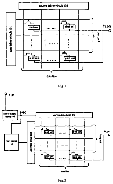
GOA circuit based on oxide semiconductor thin film transistor
The present invention provides a GOA circuit based on oxide semiconductor thin film transistor.
US 9,767,760 B2 · Assignee: LAPIS SEMICONDUCTOR CO., LTD. · Inventors: Takahashi; Yuuichi
Sheet 1 of 8 from the published document. All sheets in the USPTO PDF
A driving device for a display device wherein the display device and a source driver are connected by a plurality of external lines. A bias voltage generating part generates a bias voltage for controlling internal operating current of the plurality of amplifiers in the source driver to supply to each amplifier via a bias voltage supply line. The bias voltage supply line is laid out such that for the amplifier connected to the external line of a longer length, the length of the bias voltage supply line from the bias voltage generating part to the amplifier is shorter so as to raise a bias voltage supplied to the amplifier.
In, for example, a liquid crystal display panel as a display device, a plurality of gate lines extending in a horizontal direction of the two-dimensional screen and a plurality of source lines extending in a vertical direction of the two-dimensional screen are arranged to intersect. Further, in the liquid crystal display panel, a source driver that applies gradation display voltages corresponding to the luminance levels of pixels denoted by an input video signal to the source lines respectively and a gate driver that applies scan signals to the gate lines respectively are incorporated (refer to, e.g., Japanese Patent Application Laid-Open No. 2004-301946). In this source driver, by making timings when the latches take in display data differ from one another by means of delay circuits using the element delays of inverter elements, the state where steep changes in the amounts of current of
1 of 8 drawing sheets so far from the published document, cropped to the drawing. Every sheet is in the USPTO PDF.
What the patent claimed, word for word. All of it is now free to use.
The present invention relates to a display-device driving device that drives a display device according to a video signal.
In, for example, a liquid crystal display panel as a display device, a plurality of gate lines extending in a horizontal direction of the two-dimensional screen and a plurality of source lines extending in a vertical direction of the two-dimensional screen are arranged to intersect. Further, in the liquid crystal display panel, a source driver that applies gradation display voltages corresponding to the luminance levels of pixels denoted by an input video signal to the source lines respectively and a gate driver that applies scan signals to the gate lines respectively are incorporated (refer to, e.g., Japanese Patent Application Laid-Open No. 2004-301946). In this source driver, by making timings when the latches take in display data differ from one another by means of delay circuits using the element delays of inverter elements, the state where steep changes in the amounts of current of the source lines occur simultaneously is avoided so as to prevent noise that would occur if in this state.
Where a liquid crystal display panel having a size greater than the chip size of the source driver is driven by a single source driver, the respective lengths of lines connecting the source driver and the source lines of the liquid crystal display panel are not the same. Thus, the wiring resistances of the lines are different, and hence times until gradation display voltages sent out from the driver reach the source lines are different. Therefore, gradation display voltages are supplied to pixels connected to source lines placed farther from the driver with greater delays, which causes the problem that display unevenness occurs.
An object of the present invention is to provide a display-device driving device that can perform image display of high quality without display unevenness even if the lengths of a plurality of lines connecting between a display device and the driver are different.
According to the present invention, there is provided a driving device for driving a display device which has a source driver that applies pixel drive voltages respectively denoting luminance levels of pixels to a plurality of source lines of the display device via external lines respectively. The source driver includes: a plurality of amplifiers provided correspondingly to the plurality of source lines respectively and configured to generate the pixel drive voltages so as to supply it to the external lines respectively, the respective one of the plurality of amplifiers having a control terminal and operating with a transition speed in accordance with a voltage supplied thereto via the control terminal; a bias voltage supply line having its opposed ends; and a bias voltage generating part that generates a bias voltage and supplies the bias voltage across the opposed ends. The bias voltage supply line is connected to the control terminal of the respective one of the amplifiers so that the respective length from the either one end of said bias voltage supply line to the respective control terminal of the amplifiers correspond in length to the external line connected to the respective one of the amplifier.
According to the present invention, there is provided a driving device for a display device which has a source driver that applies pixel drive voltages respectively denoting luminance levels of pixels to a plurality of source lines of the display device via external lines respectively. The source driver includes a first group of amplifiers provided corresponding to source lines in charge of the left region of a two-dimensional screen of the display device from among the plurality of source lines and that generate the pixel drive voltages to send onto the external lines respectively; a second group of amplifiers provided corresponding to source lines in charge of the right region of the two-dimensional screen of the display device from among the plurality of source lines and that generate the pixel drive voltages to send onto the external lines respectively; a bias voltage generating part that generates a bias voltage for controlling output delays of the first and second groups of amplifiers; a first bias voltage supply line via which to supply the bias voltage to the first group of amplifiers; and a second bias voltage supply line via which to supply the bias voltage to the second group of amplifiers. The bias voltage generating part has a first terminal connected to one end of the first bias voltage supply line, a second terminal connected to the other end thereof, a third terminal connected to one end of the second bias voltage supply line, and a fourth terminal connected to the other end thereof. In a first mode, the bias voltage is applied to the first terminal and the third terminal, and simultaneously a voltage lower than the bias voltage is applied to the second terminal and the fourth terminal, and in a second mode, with the second terminal and the fourth terminal being short-circuited, the bias voltage is applied to the first terminal, and simultaneously a voltage lower than the bias voltage is applied to the third terminal, and in a third mode, with the second terminal and the fourth terminal being short-circuited, the bias voltage is applied to the third terminal, and simultaneously a voltage lower than the bias voltage is applied to the first terminal. The longer the length of the external line connected to any of the amplifiers is, the shorter the length of the first and second bias voltage supply lines connecting a terminal to which the bias voltage is applied from among the first and third terminals and an input terminal of the amplifier is.
FIG. 1 is a block diagram showing a display apparatus including a driving device according to the present invention;
FIG. 2 is a block diagram showing the internal configuration of a source driver 3 ;
FIG. 3 is a diagram showing the internal configuration of an output amplifier circuit 134 ;
FIG. 4 is a block diagram showing another example of the display apparatus including the driving device according to the present invention;
FIG. 5 is a block diagram showing another example of the internal configuration of the source driver 3 ;
FIG. 6 is a block diagram showing another example of the display apparatus including the driving device according to the present invention;
FIG. 7 is a block diagram showing another example of the internal configuration of the source driver 3 ; and
FIG. 8 is a diagram showing another example of the output amplifier circuit 134 .
An embodiment of the present invention will be described in detail below with reference to the drawings.
FIG. 1 is a diagram showing schematically the configuration of a display apparatus having incorporated therein a driving device for a display device according to the present invention. As shown in FIG. 1 , this display apparatus includes a drive control part 1 , a scan driver 2 , a source driver 3 , and a display device 20 .
The display device 20 is constituted by, e.g., a liquid crystal or organic EL panel, or the like. In the display device 20 , there are formed m number of horizontal scan lines S.sub.1 to S.sub.m (m is a natural number of two or greater), which extend in a horizontal direction of a two-dimensional screen and n number of source lines D.sub.1 to D.sub.n (n is a natural number of two or greater), which extend in a vertical direction of the two-dimensional screen. Further, in each of the intersection regions of the horizontal scan lines and the source lines, a display cell for a pixel is formed.
The drive control part 1 extracts a horizontal synchronizing signal from a video signal to supply this signal to the scan driver 2 . Further, the drive control part 1 generates a sequence of pixel data PD each denoting the luminance level of a pixel in, e.g., eight bits based on this video signal to supply this sequence as a pixel data signal PDS to the source driver 3 .
The scan driver 2 generates horizontal scan pulses synchronous with the above horizontal synchronizing signal to apply them sequentially, respectively to the scan lines S.sub.1 to S.sub.m of the display device 20 .
The source driver 3 is formed on, e.g., a semiconductor chip and takes in the sequence of pixel data PD in the pixel data signal PDS. Each time that one horizontal scan line worth of, i.e., n number of pixel data PD, where n is the total number of the source lines, are taken in, the source driver 3 converts the n number of pixel data PD taken in into pixel drive voltages having voltage values corresponding to the respective luminance levels denoted by them to apply to the source lines D.sub.1 to D.sub.n of the display device 20 .
FIG. 2 is a block diagram showing the internal configuration of the source driver 3 . As shown in FIG. 2 , the source driver 3 includes a shift register 131 , a data latch part 132 , a gradation voltage converter circuit 133 , and an output amplifier circuit 134 .
The shift register 131 takes in the sequence of pixel data PD from the pixel data signal PDS supplied from the drive control part 1 to supply one horizontal scan line worth (n number) of pixel data PD as pixel data P.sub.1 to P.sub.n to the data latch part 132 .
The data latch part 132 takes in the pixel data P.sub.1 to P.sub.n to supply them as pixel data R.sub.1 to R.sub.n to the gradation voltage converter circuit 133 .
The gradation voltage converter circuit 133 converts the above pixel data R.sub.1 to R.sub.n to pixel drive voltages V.sub.1 to V.sub.n having voltage values corresponding to their respective luminance levels to supply to the output amplifier circuit 134 . The output amplifier circuit 134 applies the pixel drive voltages V.sub.1 to V.sub.n amplified to a desired level, as pixel drive voltages G.sub.1 to G.sub.n, to the source lines D.sub.1 to D.sub.n of the display device respectively. The output amplifier circuit 134 is put in a bias voltage set mode, that is, one of a V-slew mode, an R-slew mode, and an L-slew mode described later, which is designated by a bias supply line setting signal BSS supplied from the drive control part 1 .
In the case where the source driver 3 having a chip size smaller than the lateral width of the display device 20 is placed along one side of the display device 20 and on the middle of the side as shown in FIGS. 1 and 2 , as to the lengths of external lines U.sub.1 to U.sub.n connecting the output amplifier circuit 134 and the source lines D.sub.1 to D.sub.n, those on the middle of the side of the display device 20 are the shortest, and, when going toward either end, those become longer. For example, where n is an even number, in the example shown in FIG. 1 , from among the external lines U.sub.1 to U.sub.n, the lengths of the external lines U.sub.Q and U.sub.Q+1 (Q=n/2) placed on the middle are the shortest, and the lengths of the external lines U.sub.1 and U.sub.n placed in both ends are the longest. Accordingly, as to the values of the wiring resistances of U.sub.1 to U.sub.n, those on the middle of the side of the display device 20 are smaller, and, when going toward either end, those become greater. Thus, as to the transmission delays on the external lines U.sub.1, U.sub.2, . . . , U.sub.Q, U.sub.Q+1, . . . , U.sub.n−1, U.sub.n, that on U.sub.1 (U.sub.n) is the largest, and the transmission delay decreases in the order of U.sub.2 (U.sub.n−1), U.sub.3 (U.sub.n−2), . . . , U.sub.Q (U.sub.Q−1).
Where n is an odd number, from among the external lines U.sub.1 to U.sub.n, the length (wiring length) of the external line U.sub.Q (Q=(n+1)/2) placed on the middle is the shortest, and the lengths of the external lines U.sub.1 and U.sub.n placed in both ends are the longest. Thus, as to the transmission delays on the external lines U.sub.1, U.sub.2, . . . , U.sub.Q−1, U.sub.Q, U.sub.Q+1, . . . , U.sub.n−1, U.sub.n, that on U.sub.1 (U.sub.n) is the largest, and the transmission delay decreases in the order of U.sub.2 (U.sub.n−1), U.sub.3 (U.sub.n−2), . . . , U.sub.Q−1 (U.sub.Q+1), U.sub.Q.
FIG. 3 is a block diagram showing the internal configuration of the output amplifier circuit 134 . As shown in FIG. 3 , the output amplifier circuit 134 has a bias voltage generating part 30 , a bias voltage supply line setting part 40 , and amplifiers AP.sub.1 to AP.sub.n respectively corresponding to the source lines D.sub.1 to D.sub.n. The bias voltage generating part 30 and the amplifiers AP.sub.1 to AP.sub.n are connected by bias voltage supply lines BL 1 and BL 2 .
The amplifiers AP.sub.1 to AP.sub.n are arranged in a line along the side thereof in the semiconductor chip. The amplifiers AP.sub.1 to AP.sub.n are constituted by, e.g., operational amplifiers and apply the pixel drive voltages G.sub.1 to G.sub.n respectively obtained by amplifying the pixel drive voltages V.sub.1 to V.sub.n supplied from the gradation voltage converter circuit 133 to the source lines D.sub.1 to D.sub.n of the display device 20 via the external lines U.sub.1 to U.sub.n respectively. A bias voltage input terminal (a control terminal), via which to input a bias voltage to control current flowing through the differential stage of the operational amplifier, i.e., internal operating current, is provided in each of the amplifiers AP.sub.1 to AP.sub.n. Hence, individually for each of the amplifiers AP.sub.1 to AP.sub.n, the internal operating current is adjusted through the bias voltage supplied to the bias voltage input terminal. The higher the bias voltage supplied to the bias voltage input terminal is, the larger the internal operating current is, and thus the amplifier AP operates at higher speed (with higher transition speed), so that its output delay becomes smaller.
The bias voltage supply line setting part 40 switches the connection of switches 31 to 36 formed in the bias voltage generating part 30 according to the bias voltage set mode designated by the bias supply line setting signal BSS.
The bias voltage generating part 30 generates various bias voltages to control the internal operating current of each of the amplifiers AP.sub.1 to AP.sub.n and supplies these to the respective bias voltage input terminals of the AP.sub.1 to AP.sub.n via the bias voltage supply lines BL 1 and BL 2 .
As shown in FIG. 3 , the bias voltage generating part 30 includes the switches 31 to 36 , a voltage generating unit 37 , and terminals T 1 to T 4 via which to output bias voltages.
The voltage generating part 37 generates voltages V 1 to V 8 which have a magnitude relation that, e.g., V 1 >V 2 >V 3 >V 4 >V 5 >V 6 >V 7 >V 8 and supplies the voltages V 1 to V 4 of them to each of the switches 31 and 32 and the voltages V 5 to V 8 to each of the switches 33 and 34 .
The switch 31 selects one of the voltages V 1 to V 4 according to a switch switching signal supplied from the bias voltage supply line setting part 40 to apply the selected voltage onto the terminal T 1 .
The switch 32 selects one of the voltages V 1 to V 4 according to a switch switching signal supplied from the bias voltage supply line setting part 40 to apply the selected voltage onto the terminal T 3 .
The switch 33 selects one of the voltages V 5 to V 8 according to a switch switching signal supplied from the bias voltage supply line setting part 40 to supply the selected voltage to the switch 35 .
The switch 34 selects one of the voltages V 5 to V 8 according to a switch switching signal supplied from the bias voltage supply line setting part 40 to supply the selected voltage to the switch 36 .
The switch 35 applies one of the voltage supplied from the switch 33 and a voltage supplied via a short line SL onto the terminal T 2 according to a switch switching signal supplied from the bias voltage supply line setting part 40 .
The switch 36 applies one of the voltage supplied from the switch 34 and a voltage supplied via the short line SL onto the terminal T 4 according to a switch switching signal supplied from the bias voltage supply line setting part 40 .
As shown in FIG. 3 , the terminal T 1 of the bias voltage generating part 30 is connected to one end of the bias voltage supply line BL 1 , and the terminal T 2 of the bias voltage generating part 30 is connected to the other end of the BL 1 . Further, the respective bias voltage input terminals of the AP.sub.1 to AP.sub.Q (a first amplifier group) placed in the left region from among the amplifiers AP.sub.1 to AP.sub.n are connected to the bias voltage supply line BL 1 . Note that as to the lengths (wiring lengths) of the bias voltage supply line BL 1 from the terminal T 1 to the respective bias voltage input terminals of the AP.sub.1 to AP.sub.Q, that for AP.sub.Q is the longest, and the length decreases in the order of AP.sub.Q−1, . . . , AP.sub.2, AP.sub.1.
Further, as shown in FIG. 3 , the terminal T 3 of the bias voltage generating part 30 is connected to one end of the bias voltage supply line BL 2 , and the terminal T 4 of the bias voltage generating part 30 is connected to the other end of the BL 2 . The respective bias voltage input terminals of the AP.sub.Q+1 to AP.sub.n (a second amplifier group) placed in the right region from among the amplifiers AP.sub.1 to AP.sub.n are connected to the bias voltage supply line BL 2 . Note that as to the lengths of the bias voltage supply line BL 2 from the terminal T 3 to the respective bias voltage input terminals of the AP.sub.Q+1 to AP.sub.n, that for AP.sub.Q+1 is the longest, and the length decreases in the order of AP.sub.Q+2, AP.sub.Q+3, . . . , AP.sub.n−2, AP.sub.n−1, AP.sub.n.
As described above, the bias voltage supply lines BL 1 and BL 2 are connected to the control terminal of the respective one of the amplifiers AP.sub.1 to AP.sub.n so that the respective length from the either one end of the bias voltage supply lines BL 1 and BL 2 to the respective control terminal of the amplifiers AP.sub.1 to AP.sub.n correspond in length to the external line U.sub.1 to U.sub.n connected to the respective one of the amplifier AP.sub.1 to AP.sub.n.
The supply of bias voltages via the bias voltage supply lines BL 1 and BL 2 shown in FIG. 3 will be described below.
First, in the example shown in FIG. 1 , since the source driver 3 is placed on the middle of one side of the display device 20 , the drive control part 1 supplies the bias supply line setting signal BSS designating the V-slew mode (first mode) to the bias voltage supply line setting part 40 . The bias voltage supply line setting part 40 , according to this bias supply line setting signal BSS designating the V-slew mode, supplies switch switching signals to the bias voltage generating part 30 to apply, e.g., the largest voltage V 1 as a bias voltage to each of the terminals T 1 and T 3 as first terminals and to apply the voltage V 8 smaller than the voltage V 1 to the terminals T 2 and T 4 as second terminals. Thus, the switch 31 applies the voltage V 1 as a bias voltage onto the bias voltage supply line BL 1 via the terminal T 1 . The switch 32 applies the voltage V 1 as a bias voltage onto the bias voltage supply line BL 2 via the terminal T 3 . The switches 33 and 35 applies the voltage V 8 onto the bias voltage supply line BL 1 via the terminal T 2 . The switches 34 and 36 applies the voltage V 8 onto the bias voltage supply line BL 2 via the terminal T 4 .
Thus, in the V-slew mode, because the potential on the terminal T 1 is at V 1 and higher than the potential V 8 on the terminal T 2 , a current flows in the direction from the terminal T 1 toward the terminal T 2 via the bias voltage supply line BL 1 . Also, because the potential on the terminal T 3 is at V 1 and higher than the potential V 8 on the terminal T 4 , a current flows in the direction from the terminal T 3 toward the terminal T 4 via the bias voltage supply line BL 2 .
As described above, the lengths of the bias voltage supply line BL 1 from the terminal T 1 to the respective bias voltage input terminals of the AP.sub.1 to AP.sub.Q are ranked from longest in the order of AP.sub.Q, AP.sub.Q−1, . . . , AP.sub.2, AP.sub.1. Accordingly, the wiring resistances are also ranked from highest in the order of AP.sub.Q, AP.sub.Q−1, . . . , AP.sub.2, AP.sub.1. Thus, the bias voltage supplied to each amplifier is, in a sense, a voltage divided according to the wiring resistance of the bias voltage supply line BL 1 ; the bias voltage having the largest voltage value is supplied to AP.sub.1; and the bias voltage supplied to AP decreases in the order of AP.sub.2, AP.sub.3, . . . , AP.sub.Q−1, AP.sub.Q.
According to these bias voltages, as to the output delays of AP.sub.1 to AP.sub.Q, that of AP.sub.1 is the smallest, and the output delay increases in the order of AP.sub.2, AP.sub.3, . . . , AP.sub.Q−1, AP.sub.Q. Meanwhile, as to the transmission delays on the external lines U.sub.1 to U.sub.Q respectively connected to the amplifiers AP.sub.1 to AP.sub.Q, that on the external line U.sub.1 is the largest, and the transmission delay decreases in the order of U.sub.1, U.sub.2, . . . , U.sub.Q−1, U.sub.Q as mentioned previously. Therefore, the application timings of the pixel drive voltages G.sub.1 to G.sub.Q that are applied to the source lines D.sub.1 to D.sub.Q via the amplifiers AP.sub.1 to AP.sub.Q and the external lines U.sub.1 to U.sub.Q respectively become the same. That is, the bias voltage supply line BL 1 is laid out in such a way that the respective lengths thereof from the terminal T 1 to the AP.sub.1 to AP.sub.Q are ranked from longest to shortest in the order of AP.sub.Q, AP.sub.Q−1, . . . , AP.sub.2, AP.sub.1 so that a higher bias voltage is supplied to the amplifier AP connected to the external line U having a longer length.
As such, by making the output delay of the amplifier AP connected to the external line U having a longer length smaller, the differences between the transmission delays on the external lines U.sub.1 to U.sub.Q are reduced. With this configuration, over the left region of the two-dimensional screen that the source lines D.sub.1 to D.sub.Q are in charge of, image display of high quality without display unevenness can be performed. Further, in the configuration shown in FIG. 3 , different bias voltages are supplied by voltage division using the wiring resistance of the bias voltage supply line BL 1 to the amplifiers AP.sub.1 to AP.sub.Q respectively, and hence the area occupied by the output amplifier circuit in the chip can be reduced as compared with the case where a dedicated bias voltage supply line is provided for each amplifier AP to supply a bias voltage thereto individually.
Meanwhile, the lengths of the bias voltage supply line BL 2 from the terminal T 3 to the respective bias voltage input terminals of the AP.sub.Q+1 to AP.sub.n are ranked from longest in the order of AP.sub.Q+1, AP.sub.Q+2, . . . , AP.sub.n−2, AP.sub.n−1, APn. Accordingly, the wiring resistances are also ranked from highest in the order of AP.sub.Q+1, AP.sub.Q+2, . . . , AP.sub.n−2, AP.sub.n−1, APn. Thus, the bias voltage supplied to each amplifier is, in a sense, a voltage divided according to the wiring resistance of the bias voltage supply line BL 2 ; the bias voltage having the largest voltage value is supplied to AP.sub.n; and the bias voltage supplied to AP decreases in the order of AP.sub.n−1, AP.sub.n−2, . . . , AP.sub.Q+2, AP.sub.Q+1.
According to these bias voltages, as to the output delays of AP.sub.Q+1 to AP.sub.n, that of AP.sub.n is the smallest, and the output delay increases in the order of AP.sub.n−1, AP.sub.n−2, . . . , AP.sub.Q+2, AP.sub.Q+1. Meanwhile, as to the transmission delays on the external lines U.sub.Q+1 to U.sub.n respectively connected to the amplifiers AP.sub.Q+1 to AP.sub.n, that on the external line U.sub.n is the largest, and the transmission delay decreases in the order of U.sub.n−1, U.sub.n−2, . . . , U.sub.Q+2, U.sub.Q+1 as mentioned previously.
Therefore, the application timings of the pixel drive voltages G.sub.Q+1 to G.sub.n that are applied to the source lines D.sub.Q+1 to D.sub.n via the amplifiers AP.sub.Q+1 to AP.sub.n and the external lines U.sub.Q+1 to U.sub.n respectively become the same. That is, the bias voltage supply line BL 2 is laid out in such a way that the respective lengths thereof from the terminal T 3 to the AP.sub.Q+1 to AP.sub.n are ranked from longest to shortest in the order of AP.sub.Q+1, AP.sub.Q+2, . . . , AP.sub.n−2, AP.sub.n−1, AP.sub.n so that a higher bias voltage is supplied to the amplifier AP connected to the external line U having a longer length.
As such, by making the output delay of the amplifier AP connected to the external line U having a longer length smaller, the differences between the transmission delays on the external lines U.sub.Q+1 to U.sub.n are reduced. With this configuration, over the right region of the two-dimensional screen that the source lines D.sub.Q+1 to D.sub.n are in charge of, image display of high quality without display unevenness can be performed. Further, in the configuration shown in FIG. 3 , different bias voltages are supplied by voltage division using the wiring resistance of the bias voltage supply line BL 2 to the amplifiers AP.sub.Q+1 to AP.sub.n respectively, and hence the area occupied by the output amplifier circuit in the chip can be reduced as compared with the case where a dedicated bias voltage supply line is provided for each amplifier AP to supply a bias voltage thereto individually.
As described above, in the output amplifier circuit 134 shown in FIG. 3 , in forming the bias voltage supply lines in order to supply the bias voltages generated by the bias voltage generating part 30 respectively to the amplifiers AP.sub.1 to AP.sub.n via the first terminals (T 1 , T 3 ) and the bias voltage supply lines (BL 1 , BL 2 ), the bias voltage supply lines are laid out in such a way that the longer the length of the external line (U.sub.1 to U.sub.n) connected to any of the amplifiers is, the shorter the length thereof from the first terminal to the amplifier is. With this configuration, the respective application timings of the pixel drive voltages G.sub.1 to G.sub.n that are applied to the source lines D.sub.1 to D.sub.n via the amplifiers AP.sub.1 to AP.sub.n and the external lines U.sub.1 to U.sub.n respectively become the same, so that image display of high quality without display unevenness is performed.
Although the above embodiment describes an example of the case where the source driver 3 having a chip size smaller than the lateral width of the display device 20 is placed on the middle of one side of the display device 20 , the position of the source driver is not limited to this. For example, as shown in FIGS. 4 and 5 , the source driver 3 may be placed along the left end side of one side of the display device 20 .
In this case, as shown in FIG. 5 , as to the lengths of the external lines U.sub.1 to U.sub.n connecting the output amplifier circuit 134 and the source lines D.sub.1 to D.sub.n, that of the external line located at the left end of one side of the display device 20 is the shortest, and when going toward the right end, the length of the external line becomes longer. In an example shown in FIG. 4 , from among the external lines U.sub.1 to U.sub.n, the external line U.sub.1 placed at the left end is the shortest in length, and the external line U.sub.n placed at the right end is the longest in length. Thus, also as to the wiring resistances of U.sub.1 to U.sub.n, that of the external line located at the left end of one side of the display device 20 is smaller, and when going toward the right end, the wire resistance of the external line becomes larger. Therefore, as to the transmission delays on the external lines U.sub.1 to U.sub.n, that on U.sub.n is the largest, and the transmission delay decreases in the order of U.sub.n−1, U.sub.n−2, . . . , U.sub.3, U.sub.2, U.sub.1.
As such, where the source driver 3 is located along the left end side of the display device 20 , the drive control part 1 supplies the bias supply line setting signal BSS designating the R-slew mode (second mode) to the bias voltage supply line setting part 40 .
The bias voltage supply line setting part 40 , according to this bias supply line setting signal BSS designating the R-slew mode, supplies switch switching signals to the bias voltage generating part 30 to apply, e.g., the largest voltage V 1 as a bias voltage to the terminal T 3 as the first terminal and to apply the voltage V 4 smaller than the voltage V 1 to the terminal T 1 as the second terminal. Further, the bias voltage supply line setting part 40 supplies switch switching signals to short-circuit the terminals T 2 and T 4 to the bias voltage generating part 30 .
Thus, the switch 32 applies the voltage V 1 as a bias voltage onto the bias voltage supply line BL 2 via the terminal T 3 . The switch 31 applies the voltage V 4 onto the bias voltage supply line BL 1 via the terminal T 1 . The switches 35 and 36 short-circuits the terminals T 2 and T 4 via a short line SL.
Thus, in the R-slew mode, because the potential on the terminal T 3 is at V 1 and higher than the potential V 4 on the terminal T 1 , a current flows in the direction from the terminal T 3 via the terminals T 4 and T 2 toward the terminal T 1 via the bias voltage supply line BL 2 , the short line SL, and the bias voltage supply line BL 1 .
The lengths of the bias voltage supply line (BL 2 , SL, BL 1 ) from the terminal T 3 to the respective bias voltage input terminals of the AP.sub.1 to AP.sub.n are ranked from longest in the order of AP.sub.1, AP.sub.2, . . . , AP.sub.n−1, AP.sub.n. Accordingly, the wiring resistances are also ranked from highest in the order of AP.sub.1, AP.sub.2, . . . , AP.sub.n−1, AP.sub.n.
Thus, the bias voltage supplied to each amplifier is, in a sense, a voltage divided according to the wiring resistance of the bias voltage supply line BL 2 , the short line SL, and the bias voltage supply line BL 1 ; the bias voltage having the largest voltage value is supplied to AP.sub.n; and the bias voltage supplied to AP decreases in the order of AP.sub.n−1, AP.sub.n−2, . . . , AP.sub.2, AP.sub.1. According to these bias voltages, as to the output delays of AP.sub.1 to AP.sub.n, that of AP.sub.n is the smallest, and the output delay increases in the order of AP.sub.n−1, AP.sub.n−2, . . . , AP.sub.2, AP.sub.1. Meanwhile, as to the transmission delays on the external lines U.sub.1 to U.sub.n respectively connected to the amplifiers AP.sub.1 to AP.sub.n, that on the external line U.sub.n is the largest, and the transmission delay decreases in the order of U.sub.n−1, U.sub.n−2, . . . , U.sub.2, U.sub.1 as mentioned previously.
Therefore, the application timings of the pixel drive voltages G.sub.1 to G.sub.n that are applied to the source lines D.sub.1 to D.sub.n via the amplifiers AP.sub.1 to AP.sub.n and the external lines U.sub.1 to U.sub.n respectively become the same. That is, the bias voltage supply lines BL 1 and BL 2 are laid out in such a way that the respective lengths thereof from the terminal T 3 to the AP.sub.1 to AP.sub.n are ranked from longest to shortest in the order of AP.sub.1, AP.sub.2, . . . , AP.sub.n−2, AP.sub.n−1, AP.sub.n so that a higher bias voltage is supplied to the amplifier AP connected to the external line U having a longer length.
As such, by making the output delay of the amplifier AP connected to the external line U having a longer length smaller, the differences between the transmission delays on the external lines U.sub.1 to U.sub.n are reduced. With this configuration, over the entire region of the two-dimensional screen that the source lines D.sub.1 to D.sub.n are in charge of, image display of high quality without display unevenness can be performed.
Or, as shown in FIGS. 6 and 7 , the source driver 3 may be placed along the right end side of the display device 20 . In this case, as shown in FIG. 6 , as to the lengths of the external lines U.sub.1 to U.sub.n connecting the output amplifier circuit 134 and the source lines D.sub.1 to D.sub.n, that of the external line located at the right end of one side of the display device 20 is the shortest, and when going toward the left end, the length of the external line becomes longer. In an example shown in FIG. 6 , from among the external lines U.sub.1 to U.sub.n, the external line U.sub.n placed at the right end is the shortest in length, and the external line U.sub.1 placed at the left end is the longest in length. Thus, also as to the wiring resistances of U.sub.1 to U.sub.n, that of the external line located at the right end of one side of the display device 20 is smaller, and when going toward the left end, the wire resistance of the external line becomes larger. Therefore, as to the transmission delays on the external lines U.sub.1 to U.sub.n, that on U.sub.1 is the largest, and the transmission delay decreases in the order of U.sub.2, U.sub.3, . . . , U.sub.n−1, Un.
As such, where the source driver 3 is located along the right end side of the display device 20 , the drive control part 1 supplies the bias supply line setting signal BSS designating the L-slew mode (third mode) to the bias voltage supply line setting part 40 .
The bias voltage supply line setting part 40 , according to this bias supply line setting signal BSS designating the L-slew mode, supplies switch switching signals to the bias voltage generating part 30 to apply, e.g., the largest voltage V 1 as a bias voltage to the terminal T 1 as the first terminal and to apply the voltage V 4 smaller than the voltage V 1 to the terminal T 3 as the second terminal. Further, the bias voltage supply line setting part 40 supplies switch switching signals to short-circuit the terminals T 2 and T 4 to the bias voltage generating part 30 . Thus, the switch 32 applies the voltage V 4 onto the bias voltage supply line BL 2 via the terminal T 3 . The switch 31 applies the voltage V 1 as a bias voltage onto the bias voltage supply line BL 1 via the terminal T 1 . The switches 35 and 36 short-circuits the terminals T 2 and T 4 via the short line SL.
Thus, in the L-slew mode, because the potential on the terminal T 1 is at V 1 and higher than the potential V 4 on the terminal T 3 , a current flows in the direction from the terminal T 1 via the terminals T 2 and T 4 toward the terminal T 3 via the bias voltage supply line BL 1 , the short line SL, and the bias voltage supply line BL 2 .
The lengths of the bias voltage supply line (BL 1 , SL, BL 2 ) from the terminal T 1 to the respective bias voltage input terminals of the AP.sub.1 to AP.sub.n are ranked from longest in the order of AP.sub.n, AP.sub.n−1, . . . , AP.sub.2, AP.sub.1. Accordingly, the wiring resistances are also ranked from highest in the order of AP.sub.n, AP.sub.n−1, . . . , AP.sub.2, AP.sub.1.
Thus, the bias voltage supplied to each amplifier is, in a sense, a voltage divided according to the wiring resistance of the bias voltage supply line BL 1 , the short line SL, and the bias voltage supply line BL 2 ; the bias voltage having the largest voltage value is supplied to AP.sub.1; and the bias voltage supplied to AP decreases in the order of AP.sub.2, AP.sub.3, . . . , AP.sub.n−1, AP.sub.n. According to these bias voltages, as to the output delays of AP.sub.1 to AP.sub.n, that of AP.sub.1 is the smallest, and the output delay increases in the order of AP.sub.2, AP.sub.3, . . . , AP.sub.n−1, AP.sub.n. Meanwhile, as to the transmission delays on the external lines U.sub.1 to U.sub.n respectively connected to the amplifiers AP.sub.1 to AP.sub.n, that on the external line U.sub.1 is the largest, and the transmission delay decreases in the order of U.sub.2, U.sub.3, . . . , U.sub.n−1, U.sub.n as mentioned previously.
Therefore, the application timings of the pixel drive voltages G.sub.1 to G.sub.n that are applied to the source lines D.sub.1 to D.sub.n via the amplifiers AP.sub.1 to AP.sub.n and the external lines U.sub.1 to U.sub.n respectively become the same. That is, the bias voltage supply lines BL 1 and BL 2 are laid out in such a way that the respective lengths thereof from the terminal T 1 to the AP.sub.1 to AP.sub.n are ranked from longest to shortest in the order of AP.sub.n, AP.sub.n−1, . . . , AP.sub.3, AP.sub.2, AP.sub.1 so that a higher bias voltage is supplied to the amplifier AP connected to the external line U having a longer length.
As such, by making the output delay of the amplifier AP connected to the external line U having a longer length smaller, the differences between the transmission delays on the external lines U.sub.1 to U.sub.n are reduced. With this configuration, over the entire region of the two-dimensional screen that the source lines D.sub.1 to D.sub.n are in charge of, image display of high quality without display unevenness can be performed.
Although in the above embodiment, in the V-slew mode, the potentials on the terminals T 3 and T 1 are set at V 1 , and the potentials on the terminals T 4 and T 2 are set at V 8 , not being limited to this, the potentials on the terminals can be set according to the differences between the transmission delays as needed. Where the differences between the transmission delays are small, for example, by setting the potentials on the terminals T 3 and T 1 at V 4 and the potentials on the terminals T 4 and T 2 at V 5 , the differences between the output delays of the amplifiers are made smaller, so that image unevenness can be suppressed more precisely. Likewise, also in the R-slew mode and L-slew mode, by setting the potentials on the terminals T 3 and T 1 according to the differences between the transmission delays as needed, image unevenness can be suppressed more precisely.
Where the voltage generating part 37 cannot generate desired bias voltages in the V-slew mode, a bias voltage amplifier may be provided to amplify bias voltages which the voltage generating part 37 applies to the terminals T 3 and T 4 .
For example, as shown in FIG. 8 , a first bias voltage amplifier 52 is provided between the bias voltage supply line BL 2 and the terminal T 3 , and a second bias voltage amplifier 51 is provided between the bias voltage supply line BL 1 and the terminal T 1 .
To sum up, the first and second bias voltage supply lines BL 1 and BL 2 are laid out in such a way that the longer the length of the external line U connected to any of the amplifiers AP belonging to the AP.sub.Q+1 to AP.sub.n (the first amplifier group) and the AP.sub.1 to AP.sub.Q (the second amplifier group) is, the shorter the length of the BL 1 and BL 2 from the terminal to which a bias voltage is applied from among the first and third terminals to the amplifier is.
This application is based on a Japanese Patent application No. 2014-042363 which is hereby incorporated by reference.
About 6,972 words. The USPTO PDF has it with every drawing.
Fees are due 3.5, 7.5 and 11.5 years after grant. This patent expired on September 19, 2025, so the fee marked "not paid" was the one that went unpaid.
DRIVING DEVICE FOR DISPLAY DEVICE
Filed Mar 2015 · published Sep 2015Driving device for display device
Filed Mar 2015 · granted Sep 2017Earlier publications, parents and continuations. None of them can still be enforced, or this patent would not be listed.
Prior art cited by the examiner or applicant. Useful when you check your own idea for novelty.
Everything on this page comes from the documents linked above.