Cross-reference to related application
This application claims priority under 35 USC 119 from Japanese Patent Application No. 2015-48639 filed on Mar. 11, 2015, the disclosure of which is incorporated by reference herein.
Background
Technical Field
An exemplary embodiment of the present invention relates to a vehicle body front portion structure.
Description of the Related Art
Japanese Patent Application Laid-Open (JP-A) No. 2002-249079 discloses a structure in which an energy-absorbing member formed of foam urethane is provided in a range from a lower portion front face of a front pillar to a lower portion front face at a dash panel side portion side. In this structure, when there is a frontal collision, a collision load is transmitted from a front wheel through the energy-absorbing member to plural vehicle body structural members. SUMMARY OF THE INVENTION Technical Problem
However, even with the conventional technology described above, if, for example, the front wheel is moved back to a joining portion between the dash panel and the front pillar when there is a frontal collision such as a micro-wrap collision or the like, a load acts in a direction of separation of the joining portion. Therefore, there is scope for improvement in regard to suppressing separation between the dash panel and the front pillar.
In consideration of the circumstances described above, an object of an exemplary embodiment of the present invention is to provide a vehicle body front portion structure that can suppress separation between a dash panel and a front pillar when there is a frontal collision such as a micro-wrap collision or the like. Solution to Problem
A vehicle body front portion structure according to a first aspect of the present invention includes: a front pillar disposed along a vehicle vertical direction at a vehicle width direction outer side end portion of a vehicle cabin front portion, the front pillar including a pillar inner panel at a vehicle width direction inner side end portion of the front pillar, the pillar inner panel including an inner side upright wall portion that extends in the vehicle vertical direction and a vehicle front-and-rear direction, and a hole portion being formed penetrating a lower portion of the inner side upright wall portion; a dash portion including a dash panel that structures a vehicle cabin front wall, a vehicle width direction outer side end portion of the dash panel being joined to the front pillar, and the dash portion separating the vehicle cabin from a power unit compartment that is located at a vehicle front side of the vehicle cabin; and a load transmission portion including a dash side structure portion that is fixed to a surface of a vehicle width direction outer side region of the dash portion, which surface faces a vehicle rear side, a pillar side structure portion that is fixed to a surface of the inner side upright wall portion of the pillar inner panel, which surface faces a vehicle width direction outer side, and an intermediate structure portion that is connected to at least one of the dash side structure portion or the pillar side structure portion, the intermediate structure portion penetrating the hole portion, and the intermediate structure portion being set at a location at which the intermediate structure portion transmits a load that acts on the dash side structure portion when there is a frontal collision to the pillar side structure portion.
According to the structure described above, the dash side structure portion of the load transmission portion is fixed to the surface that faces the vehicle rear side of the vehicle width direction outer side region of the dash portion. Therefore, when there is a frontal collision, if the dash portion is pushed from a vehicle front side of the joining portion between the dash panel and the front pillar, a load toward the vehicle rear side acts on the dash portion and the dash side structure portion of the load transmission portion, and a load toward the vehicle width direction inner side acts on the same in a direction of detachment from the front pillar.
In this case, the load transmission portion is provided with the pillar side structure portion and the intermediate structure portion in addition to the dash side structure portion. The pillar side structure portion is fixed to the surface that faces the vehicle width direction outer side of the inner side upright wall portion of the pillar inner panel. The intermediate structure portion is connected with at least one of the dash side structure portion or the pillar side structure portion, penetrates the hole portion in the inner side upright wall portion and, when there is a frontal collision, transmits a load acting on the dash side structure portion to the pillar side structure portion. Thus, the load transmission portion is capable of bearing a load as part of a load transmission path, and a load that acts on the joining portion between the dash panel and the front pillar when there is a frontal collision is reduced correspondingly.
In a vehicle body front portion structure according to a second aspect of the present invention, in the first aspect, the load transmission portion is structured by two members, the two members being a dash side member including the dash side structure portion and a pillar side member including the pillar side structure portion, and the intermediate structure portion is provided at the dash side member or the pillar side member, a vehicle front side end portion of the pillar side member extends toward a vehicle front side, and a rear projection portion is formed at a vehicle width direction outer side end portion of the dash side member, the rear projection portion projecting toward the vehicle rear side and being located at the vehicle width direction outer side relative to the vehicle front side end portion of the pillar side member.
According to the structure described above, the load transmission portion is structured by two members, the dash side member and the pillar side member. The dash side member is fixed to the vehicle width direction outer side region of the dash portion, and the pillar side member is fixed to the inner side upright wall portion of the pillar inner panel. Therefore, assembly characteristics are better than in a case in which the load transmission portion is structured by a single member. In addition, the vehicle front side end portion of the pillar side member extends to the vehicle front side and, correspondingly, the rear projection portion that is formed at the vehicle width direction outer side end portion of the dash side member projects to the vehicle rear side and is located at the vehicle width direction outer side relative to the vehicle front side end portion of the pillar side member. Therefore, when there is a frontal collision, if the dash side member moves diagonally to the vehicle rear and to the vehicle width direction inner side along with the vehicle width direction outer side region of the dash portion, the rear projection portion of the dash side member engages with the vehicle front side end portion of the pillar side member and transmits the load acting on the dash side member to the pillar side member.
In a vehicle body front portion structure according to a third aspect of the present invention, in the second aspect, the pillar side member includes the intermediate structure portion, the intermediate structure portion including a portion that extends to a vehicle width direction inner side from the vehicle front side end portion of the pillar side structure portion, a front projection portion that projects toward the vehicle front side is formed at a vehicle width direction inner side end portion of the intermediate structure portion, and the rear projection portion of the dash side member is located at the vehicle width direction outer side relative to the front projection portion of the pillar side member.
According to the structure described above, when there is a frontal collision, the rear projection portion of the dash side member may be engaged with the front projection portion of the pillar side member within a range in a vehicle front view in which the dash side member overlaps with a range in which the collision load is received via the dash portion. Therefore, when there is a frontal collision, the collision load may be reliably transmitted from the dash side member to the pillar side member. Thus, even when the load transmission portion is structured by two members, separation of the dash panel from the front pillar when there is a frontal collision may be reliably suppressed.
In a vehicle body front portion structure according to a fourth aspect of the present invention, in the third aspect, an incision portion with a semi-circular shape in a vehicle side view is formed at the rear projection portion or the front projection portion, the incision portion being open to a side of a direction of projection, and an inflected portion with an L-shape in a vehicle plan view is formed by the other of the rear projection portion or the front projection portion and a portion connecting with the other of the rear projection portion or the front projection portion, the inflected portion being set to be within a range in the vehicle vertical direction that corresponds with a location at which the incision portion is formed.
According to the structure described above, even if there is irregularity in the input direction of a collision load when there is a frontal collision and the dash side member tilts in the vehicle side view, the portion connecting with the other of the rear projection portion or the front projection portion enters into the inside of the incision portion formed in the one of the rear projection portion or the front projection portion. Thus, a peripheral portion of the incision portion formed in the one of the rear projection portion or the front projection portion may be reliably engaged with the other of the rear projection portion or the front projection portion.
In a vehicle body front portion structure according to a fifth aspect of the present invention, in the third aspect, a penetrating hole with a circular shape is formed in the rear projection portion, the penetrating hole penetrating in a vehicle width direction, and the pillar side member includes the intermediate structure portion, the intermediate structure portion penetrating the penetrating hole.
According to the structure described above, even if there is irregularity in the input direction of a collision load when there is a frontal collision and the dash side member tilts in the vehicle side view, a periphery portion of the penetrating hole in the rear projection portion of the dash side member may be reliably engaged with the front projection portion of the pillar side member.
In a vehicle body front portion structure according to a sixth aspect of the present invention, in the first aspect, the load transmission portion is structured by a single member that includes the dash side structure portion, the intermediate structure portion and the pillar side structure portion.
According to the structure described above, when there is a frontal collision, a collision load may be transmitted from the dash side structure portion via the intermediate structure portion to the pillar side structure portion from when the collision load first acts on the dash side structure portion. Advantageous Effects of Invention
According to the vehicle body front portion structure in accordance with the exemplary embodiment of the present invention, when there is a frontal collision such as a micro-wrap collision or the like, separation of the dash panel from the front pillar may be suppressed.
Brief description of the drawings
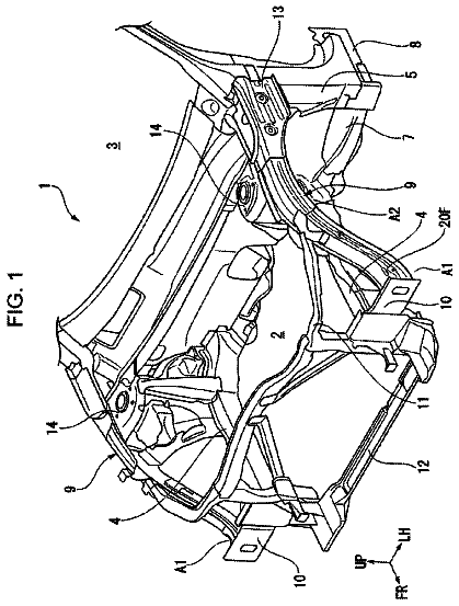
FIG. 1 is a perspective view showing a vehicle body front portion structure in accordance with a first exemplary embodiment of the present invention.
FIG. 2 is a magnified plan sectional view showing a magnification of a state cut along line 2 - 2 in FIG. 1 .
FIG. 3 is an exploded perspective view showing a magnification of a dash side member, a pillar side member and a bracket for assembly that are shown in FIG. 2 .
FIG. 4 is a plan sectional view showing a state during a frontal collision in the same sectional view as FIG. 2 .
FIG. 5A is a perspective view showing a first variant example of a member for fixing the pillar side member to a pillar inner panel.
FIG. 5B is a perspective view showing a second variant example of the member for fixing the pillar side member to the pillar inner panel.
FIG. 6 is an exploded perspective view showing a first variant example of the dash side member and the pillar side member.
FIG. 7 is an exploded perspective view showing a second variant example of the dash side member and the pillar side member.
FIG. 8 is a plan sectional view showing a vehicle body front portion structure in accordance with a second exemplary embodiment of the present invention.
FIG. 9 is a plan sectional view showing a vehicle body front portion structure in accordance with a third exemplary embodiment of the present invention. DETAILED DESCRIPTION OF PREFERRED EMBODIMENTS First Exemplary Embodiment
A vehicle body front portion structure according to a first exemplary embodiment of the present invention is described using FIG. 1 to FIG. 4 . An arrow FR that is shown as appropriate in these drawings indicates a vehicle front side, an arrow UP indicates a vehicle upper side, and an arrow IN indicates a vehicle width direction inner side. In the following descriptions, where the directions front, rear, up, down, left and right are recited without being particularly specified, the same represent the front and rear in the vehicle front-and-rear direction, up and down in the vehicle vertical direction, and left and right in the vehicle left-and-right direction (a vehicle width direction).
FIG. 1 shows a perspective view of a state in which a portion of a vehicle body left side of an automobile (a vehicle) 12 is viewed diagonally from the front side at a vehicle width direction outer side. A vehicle body front portion structure 10 according to the present exemplary embodiment is employed in this automobile 12 . The vehicle body right side is not shown in FIG. 1 but the vehicle body front portion structure 10 is basically structured with left-and-right symmetry.
As is shown in FIG. 1 , a front pillar 20 is disposed in the vehicle vertical direction at a vehicle width direction outer side end portion of a front portion of a vehicle cabin 14 . The front pillar 20 is provided standing to the vehicle upper side from a front end portion of a rocker 16 . The rocker 16 extends in the vehicle front-and-rear direction at a lower portion of a vehicle side portion 12 A. An upper end portion of the front pillar 20 is joined to a front end portion of a roof side rail (not shown in the drawings). The roof side rail extends in the vehicle front-and-rear direction at an upper portion of the vehicle side portion 12 A. A center pillar (which is not shown in the drawings) is provided standing to the vehicle upper side from a length direction middle portion of the rocker 16 . An upper end portion of the center pillar is joined to a length direction middle portion of the roof side rail.
The front pillar 20 , the rocker 16 , the roof side rail and the center pillar are all vehicle body framework members with closed cross section structures and structure a door opening portion 18 . That is, the front pillar 20 is disposed in the vehicle vertical direction at a front edge side of the door opening portion 18 . The door opening portion 18 communicates between the exterior and the interior of the vehicle cabin and can be opened and closed by a side door (which is not shown in the drawings).
FIG. 2 shows a magnified plan sectional view of a state cut along line 2 - 2 in FIG. 1 . The front pillar 20 is provided with a pillar inner panel 22 and a pillar outer panel 24 . The pillar inner panel 22 is disposed at the vehicle cabin interior side and structures an inner plate of the front pillar 20 . The pillar outer panel 24 is disposed at the vehicle cabin exterior side of the pillar inner panel 22 and structures an outer plate of the front pillar 20 .
A cross-sectional shape of the pillar inner panel 22 in the vehicle plan view is formed in a pork pie hat shape, an opening portion of which is oriented to the vehicle width direction outer side. The pillar inner panel 22 is provided with a front flange portion 22 A that is formed at a vehicle front side end portion thereof and a rear flange portion 22 B that is formed at a vehicle rear side end portion thereof. By contrast, the pillar outer panel 24 is formed in a substantially flat shape that extends roughly in the vehicle front-and-rear direction and the vehicle vertical direction. More specifically, a cross-sectional shape of the pillar outer panel 24 in the vehicle plan view is formed in a shape in which a vehicle front-and-rear direction middle portion thereof is recessed slightly to the vehicle width direction outer side. The pillar outer panel 24 is provided with a front flange portion 24 A that is formed at a vehicle front side end portion thereof and a rear flange portion 24 B that is formed at a vehicle rear side end portion thereof.
The front flange portion 22 A of the pillar inner panel 22 and the front flange portion 24 A of the pillar outer panel 24 are joined together by welding. The rear flange portion 22 B of the pillar inner panel 22 and the rear flange portion 24 B of the pillar outer panel 24 are joined together by welding. Because of these joinings, a closed cross section 20 X is formed between the pillar inner panel 22 and the pillar outer panel 24 . The closed cross section 20 X extends substantially in the vehicle vertical direction. A portion of a side outer panel (not shown in the drawings) is disposed at the vehicle width direction outer side of the pillar outer panel 24 .
The pillar inner panel 22 is provided with a front wall portion 22 C and a rear wall portion 22 D. The front wall portion 22 C is inflected from a vehicle rear side end portion of the front flange portion 22 A and extends to the vehicle width direction inner side. The rear wall portion 22 D is inflected from a vehicle front side end portion of the rear flange portion 22 B and extends to the vehicle width direction inner side. The front wall portion 22 C and rear wall portion 22 D are disposed to oppose one another in the vehicle front-and-rear direction and are slightly angled in directions to approach one another toward the vehicle width direction inner side in the vehicle plan view. A vehicle width direction inner side end portion of the front wall portion 22 C and a vehicle width direction inner side end portion of the rear wall portion 22 D are connected in the vehicle front-and-rear direction by an inner side upright wall portion 22 E. The inner side upright wall portion 22 E of the pillar inner panel 22 extends in the vehicle vertical direction and the vehicle front-and-rear direction at a vehicle width direction inner side end portion of the front pillar 20 .
A hole portion 22 H is formed penetrating the inner side upright wall portion 22 E forward of a vehicle front-and-rear direction middle portion of the inner side upright wall portion 22 E. The hole portion 22 H is set at a vehicle vertical direction location that corresponds with an vertical direction middle portion of a front wheel 28 , that is, at a lower portion of the inner side upright wall portion 22 E. The front wheel 28 is provided with a wheel 28 A and a tire 28 B. The wheel 28 A includes a vertical circular plate portion at a turning axis thereof. The tire 28 B is retained at an outer periphery portion of the wheel 28 A. The hole portion 22 H in the inner side upright wall portion 22 E of the pillar inner panel 22 is formed in a semi-circular shape (a “D” shape) with a circular arc portion at the vehicle front side thereof in a vehicle side view. An extension 26 is disposed at the vehicle width direction inner side of the inner side upright wall portion 22 E. The extension 26 is attached to the inner side upright wall portion 22 E at a vehicle rear side of the hole portion 22 H. A rear portion of the extension 26 protrudes to the vehicle width direction inner side and a vehicle rear side from the closed cross section 20 X of the front pillar 20 . An electronic control unit (ECU, not shown in the drawings) is mounted at a rear portion of the extension 26 .
A dash portion 30 is disposed between the left and right front pillars 20 . The dash portion 30 includes a dash panel 32 and a dash cross-member 34 . The dash portion 30 separates the vehicle cabin 14 from a power unit compartment 36 that is disposed at the vehicle front side of the vehicle cabin 14 . The dash panel 32 is disposed between the inner side upright wall portions 22 E of the left and right front pillars 20 that structure a vehicle cabin front wall. A side flange portion 32 F that protrudes to the vehicle rear side is formed at each vehicle width direction outer side end portion of the dash panel 32 . The side flange portion 32 F of the dash panel 32 is joined by spot welding to the extension 26 and a vehicle front-and-rear direction middle portion of the inner side upright wall portion 22 E of the front pillar 20 (more specifically, a region at the vehicle rear side relative to the hole portion 22 H).
As shown in FIG. 1 and FIG. 2 , the dash cross-member 34 is disposed at a front face lower portion of the dash panel 32 . The dash cross-member 34 has a long, narrow shape extending in the vehicle width direction. As shown in FIG. 1 , a region of the dash cross-member 34 that excludes the two length direction end portions thereof is formed in a pork pie hat shape, an opening portion of which is oriented to the vehicle rear side in a vehicle side view. The dash cross-member 34 is provided with an upper flange portion 34 A formed at a vehicle upper side end portion thereof and a lower flange portion 34 B formed at a vehicle lower side end portion thereof. The upper flange portion 34 A and lower flange portion 34 B of the dash cross-member 34 are joined by spot welding or the like to a front face lower portion of the dash panel 32 . Thus, the dash cross-member 34 forms a closed cross section 30 X with the dash panel 32 (see FIG. 2 ).
The dash cross-member 34 is provided with an upper wall portion 34 C and a lower wall portion (not shown in the drawings). The upper wall portion 34 C is inflected from a vehicle lower side end portion of the upper flange portion 34 A and extends to the vehicle front side. The lower wall portion is inflected from a vehicle upper side end portion of the lower flange portion 34 B and extends to the vehicle front side. The upper wall portion 34 C and the lower wall portion are disposed to oppose one another in the vehicle vertical direction and are slightly angled in directions to approach one another toward the vehicle front side in the vehicle side view. A vehicle front side end portion of the upper wall portion 34 C and a vehicle front side end portion of the lower wall portion are connected in the vehicle vertical direction by a front wall portion 34 E. The front wall portion 34 E extends in the vehicle vertical direction and the vehicle width direction.
The dash cross-member 34 is provided with a side portion flange portion 34 S at each of the two length direction end portions thereof. As shown in FIG. 2 , the side portion flange portion 34 S is joined by spot welding to the front wall portion 22 C and a front end portion (i.e., a region at the vehicle front side relative to the hole portion 22 H) of the inner side upright wall portion 22 E of the pillar inner panel 22 . The hole portion 22 H that is formed penetrating the inner side upright wall portion 22 E of the front pillar 20 described above faces into an interior space of the closed cross section 30 X formed by the dash panel 32 and the dash cross-member 34 .
A load transmission portion 40 is set in a range extending through both the closed cross section 30 X of the dash portion 30 and the closed cross section 20 X of the front pillar 20 . The load transmission portion 40 is structured by two members, a dash side member 42 and a pillar side member 44 . The dash side member 42 structures a dash side structure portion 40 A. The pillar side member 44 structures a pillar side structure portion 40 B and an intermediate structure portion 40 C. FIG. 3 shows the dash side member 42 and the pillar side member 44 in an exploded perspective view.
The dash side member 42 is structured by, for example, a plate-shaped member fabricated of metal. The dash side member 42 is a member whose shape in the vehicle plan view is an L-shape and that is long in the vehicle width direction. As shown in FIG. 2 , the dash side member 42 is disposed adjacent to a surface 34 R of a vehicle width direction outer side region 34 Z of the front wall portion 34 E of the dash cross-member 34 (the dash portion 30 ), which surface 34 R faces to the vehicle rear side.
The dash side member 42 is provided with a base plate portion 42 A that, in a state in which the dash side member 42 is assembled to the dash portion 30 , extends in the vehicle width direction along the front wall portion 34 E of the dash cross-member 34 . The base plate portion 42 A is superposed with the surface 34 R that faces the vehicle rear side of the vehicle width direction outer side region 34 Z of the front wall portion 34 E of the dash cross-member 34 , and the base plate portion 42 A is fixed by spot welding to the vehicle width direction outer side region 34 Z. Through-holes 42 H are formed penetrating the base plate portion 42 A of the dash side member 42 shown in FIG. 3 . The through-holes 42 H are reference hole for when spot welding is being performed.
As shown in FIG. 2 and FIG. 3 , a rear projection portion 42 B is formed at a vehicle width direction outer side end portion of the dash side member 42 . The rear projection portion 42 B is inflected from the vehicle width direction outer side end portion of the base plate portion 42 A and projects to the vehicle rear side. An incision portion 42 C is formed in the rear projection portion 42 B of the dash side member 42 . The incision portion 42 C is cut away in a semi-circular shape in the vehicle side view, opening to the vehicle rear side (i.e., a side of a direction of projection of the rear projection portion 42 B).
The pillar side member 44 is, for example, fabricated of metal. The pillar side member 44 is a member that is longer in the vehicle front-and-rear direction than in the vehicle width direction. A vehicle vertical direction dimension of the pillar side member 44 is specified to be smaller than a vehicle vertical direction dimension of the open end of the incision portion 42 C of the dash side member 42 . As shown in FIG. 2 , the pillar side member 44 is provided with a base plate portion 44 A. The base plate portion 44 A is disposed adjacent to a surface 22 S of the inner side upright wall portion 22 E of the pillar inner panel 22 , which surface 22 S faces to the vehicle width direction outer side. The base plate portion 44 A is fixed to the inner side upright wall portion 22 E via a bracket 46 . The base plate portion 44 A structures the pillar side structure portion 40 B of the load transmission portion 40 . In the state in which the base plate portion 44 A is assembled to the front pillar 20 , the base plate portion 44 A extends in the vehicle front-and-rear direction and the vehicle vertical direction along the inner side upright wall portion 22 E of the pillar inner panel 22 and is disposed with the length direction thereof in the vehicle front-and-rear direction.
The bracket 46 is provided for fixing the pillar side member 44 to the pillar inner panel 22 . As shown in FIG. 3 , a shape of the bracket 46 in a vehicle front view is formed in a pork pie hat shape, an opening portion of which is oriented to the vehicle width direction inner side, and a length direction of the bracket 46 is in the vehicle front-and-rear direction. That is, the bracket 46 is provided with a recessed slot formation portion 46 X, an upper flange portion 46 A and a lower flange portion 46 B. An opening portion of the bracket 46 is oriented to the vehicle width direction inner side and the recessed slot formation portion 46 X extends in the vehicle front-and-rear direction. The upper flange portion 46 A is formed at a vehicle upper side end portion of the bracket 46 and the lower flange portion 46 B is formed at a vehicle lower side end portion of the bracket 46 . In FIG. 3 , the bracket 46 is illustrated by two-dot chain lines in the state in which the pillar side member 44 is attached.
The recessed slot formation portion 46 X is provided with an upper wall portion 46 C and a lower wall portion 46 D. The upper wall portion 46 C is inflected from a vehicle lower side end portion of the upper flange portion 46 A and extends to the vehicle width direction outer side. The lower wall portion 46 D is inflected from a vehicle upper side end portion of the lower flange portion 46 B and extends to the vehicle width direction outer side. A vehicle width direction outer side end portion of the upper wall portion 46 C and a vehicle width direction outer side end portion of the lower wall portion 46 D are connected in the vehicle vertical direction by an outer side upright wall portion 46 E. The outer side upright wall portion 46 E extends in the vehicle vertical direction and the vehicle front-and-rear direction and is disposed with a length direction thereof in the vehicle front-and-rear direction.
A slot depth of the recessed slot formation portion 46 X (i.e., a recess amount in the vehicle width direction) is specified to be substantially equal to a thickness in the vehicle width direction of the base plate portion 44 A of the pillar side member 44 . An opening width of the recessed slot formation portion 46 X in the vehicle vertical direction is specified to be slightly larger than a width in the vehicle vertical direction of the base plate portion 44 A of the pillar side member 44 . The base plate portion 44 A of the pillar side member 44 is disposed at the recess slot interior side of the recessed slot formation portion 46 X, and the base plate portion 44 A of the pillar side member 44 is fixed to the outer side upright wall portion 46 E by arc welding. The upper flange portion 46 A and the lower flange portion 46 B are superposed with the surface 22 S that faces the vehicle width direction outer side at a rear portion (i.e., a region at the vehicle rear side relative to the hole portion 22 H) of the inner side upright wall portion 22 E of the pillar inner panel 22 shown in FIG. 2 , and the upper flange portion 46 A and lower flange portion 46 B are fixed by spot welding (not shown in the drawings) to the inner side upright wall portion 22 E.
The pillar side member 44 is provided with a front side structure portion 44 X that is connected to the base plate portion 44 A and penetrates the hole portion 22 H. The front side structure portion 44 X of the pillar side member 44 includes an inner projection portion 44 B that extends to the vehicle width direction inner side from a vehicle front side end portion of the base plate portion 44 A. A front projection portion 44 C that projects to the vehicle front side is formed at a vehicle width direction inner side end portion of the inner projection portion 44 B. In the present exemplary embodiment, the front projection portion 44 C is inflected from the vehicle width direction inner side end portion of the inner projection portion 44 B and extends to the vehicle front side. That is, an inflected portion 44 L, Which has an L-shape in the vehicle plan view, is formed by the front projection portion 44 C and a portion connecting with the front projection portion 44 C (i.e., the inner projection portion 44 B). A vehicle front side end portion of the pillar side member 44 , that is, the front projection portion 44 C, is located at the vehicle width direction inner side relative to the rear projection portion 42 B of the dash side member 42 . The inflected portion 44 L is set to be within a range in the vehicle vertical direction that corresponds with the location at which the incision portion 42 C of the rear projection portion 42 B is formed.
As shown in FIG. 3 , the front projection portion 44 C structures a portion of a semi-circular protrusion portion 44 D. The semi-circular protrusion portion 44 D protrudes in the vehicle vertical direction and the vehicle front direction from the vehicle width direction inner side end portion of a substantially rectangular rod-shaped portion of the inner projection portion 44 B. The semi-circular protrusion portion 44 D is formed in a semi-circular shape (a “D” shape) with a circular arc portion at the vehicle front side thereof in the vehicle side view. The semi-circular protrusion portion 44 D is an element that may be broadly understood as a grapple-shaped portion. The semi-circular protrusion portion 44 D of the pillar side member 44 and the rear projection portion 42 B of the dash side member 42 constitute a latch structure in which the semi-circular protrusion portion 44 D and the rear projection portion 42 B may engage with one another when there is a frontal collision. The semi-circular protrusion portion 44 D is specified to be slightly smaller than the incision portion 42 C.
The front side structure portion 44 X described above of the pillar side member 44 shown in FIG. 2 structures the intermediate structure portion 40 C of the load transmission portion 40 . The front side structure portion 44 X is set to a location at which, when there is a frontal collision, the front side structure portion 44 X receives a load acting on the dash side member 42 (the dash side structure portion 40 A) and transmits the load to the base plate portion 44 A of the pillar side member 44 (the pillar side structure portion 40 B). Operation and Effects
Now, operation and effects of the above exemplary embodiment are described. Principally described below is operation when there is a frontal collision of a collision body (a barrier) with one vehicle width direction side of the automobile 12 . A micro-wrap collision, an offset collision and the like may be mentioned as examples of this kind of frontal collision. The term “micro-wrap collision” refers to a collision condition in which a portion of an automobile that is at the vehicle width direction outer side relative to a front side member collides with a collision body.
When the automobile 12 has a frontal collision such as a micro-wrap collision or the like, a portion of the front wheel 28 is moved back by a collision load during the collision, to between a vehicle width direction outer side region of the dash panel 32 and the front pillar 20 . A load from the front wheel 28 acts toward the vehicle rear side on the dash portion 30 and the front pillar 20 . As illustrated in FIG. 4 , a load f 1 acts on the dash portion 30 toward the vehicle width direction inner side and a load f 2 acts on the front pillar 20 toward the vehicle width direction outer side.
In the present exemplary embodiment, as shown in FIG. 2 , the dash side structure portion 40 A of the load transmission portion 40 is fixed to the surface 34 R facing the vehicle rear side at the vehicle width direction outer side region 34 Z of the dash cross-member 34 (the dash portion 30 ). Therefore, when there is a frontal collision, if the dash portion 30 is pushed from the vehicle front side at the joining portion between the dash panel 32 and the front pillar 20 , a load toward the vehicle rear side acts on the dash portion 30 and the dash side structure portion 40 A of the load transmission portion 40 and, as illustrated in FIG. 4 , the load f 1 acts toward the vehicle width direction inner side, which is a direction of detachment from the front pillar 20 .
As shown in FIG. 2 , the load transmission portion 40 is provided with the pillar side structure portion 40 B and intermediate structure portion 40 C in addition to the dash side structure portion 40 A. The pillar side structure portion 40 B is fixed to the surface 22 S of the inner side upright wall portion 22 E of the pillar inner panel 22 that faces the vehicle width direction outer side. The intermediate structure portion 40 C is connected with the pillar side structure portion 40 B and penetrates the hole portion 22 H of the inner side upright wall portion 22 E. The intermediate structure portion 40 C receives a load that acts on the dash side structure portion 40 A when there is a frontal collision and transmits the load to the pillar side structure portion 40 B. That is, the load transmission portion 40 is capable of bearing a load as part of a load transmission path, and a load that acts on the joining portion of the dash panel 32 and the front pillar 20 when there is a frontal collision is reduced correspondingly.
As illustrated in FIG. 4 , the load f 2 acts on the inner side upright wall portion 22 E of the pillar inner panel 22 toward the vehicle width direction outer side, and the pillar side structure portion 40 B is fixed to the side of the surface 22 S facing the vehicle width direction outer side of this inner side upright wall portion 22 E. Therefore, even though the load f 1 acts toward the vehicle width direction inner side from the dash side structure portion 40 A through the intermediate structure portion 40 C to the pillar side structure portion 40 B, displacement of the pillar side structure portion 40 B to the vehicle width direction inner side is suppressed. Moreover, when the load f 1 acts toward the vehicle width direction inner side on the pillar side structure portion 40 B, a load acts in a compression direction on a joining portion between the bracket 46 and the inner side upright wall portion 22 E of the pillar inner panel 22 . Therefore, separation of this joining portion is effectively suppressed.
In the present exemplary embodiment, as shown in FIG. 2 , the load transmission portion 40 is structured by two members, the dash side member 42 and the pillar side member 44 . The dash side member 42 is fixed to the vehicle width direction outer side region 34 Z of the dash portion 30 (the dash cross-member 34 ), and the pillar side member 44 is fixed to the inner side upright wall portion 22 E of the pillar inner panel 22 . Therefore, assembly characteristics in a joining process are more preferable than in a case in which a load transmission portion is structured by a single member.
The vehicle front side end portion of the pillar side member 44 (i.e., the front projection portion 44 C) extends to the vehicle front side. Meanwhile, the rear projection portion 42 B formed at the vehicle width direction outer side end portion of the dash side member 42 projects to the vehicle rear side and is disposed at the vehicle width direction outer side relative to the vehicle front side end portion of the pillar side member 44 (the front projection portion 44 C). Therefore, when there is a frontal collision, if the dash side member 42 moves diagonally to the vehicle width direction inner side toward the vehicle rear along with a vehicle width direction outer side region of the dash portion 30 , the rear projection portion 42 B of the dash side member 42 engages with the vehicle front side end portion of the pillar side member 44 (the front projection portion 44 C) and the load acting on the dash side member 42 is transmitted to the pillar side member 44 .
The description continues in the full USPTO document.
 Lapsed, fee not paid6 drawings