Background of the invention
Field of the Invention
The present invention relates to a method for receiving control information through an enhanced physical downlink control channel (EPDCCH).
Related Art
3GPP (3rd Generation Partnership Project) LTE (Long Term Evolution) that is an advancement of UMTS (Universal Mobile Telecommunication System) is being introduced with 3GPP release 8. In 3GPP LTE, OFDMA (orthogonal frequency division multiple access) is used for downlink, and SC-FDMA (single carrier-frequency division multiple access) is used for uplink. The 3GPP LTE adopts MIMO (multiple input multiple output) having maximum four antennas. Recently, a discussion of 3GPP LTE-A (LTE-Advanced) which is the evolution of the 3GPP LTE is in progress.
As set forth in 3GPP TS 36.211 V10.4.0, the physical channels in 3GPP LTE may be classified into data channels such as PDSCH (physical downlink shared channel) and PUSCH (physical uplink shared channel) and control channels such as PDCCH (physical downlink control channel), PCFICH (physical control format indicator channel), PHICH (physical hybrid-ARQ indicator channel) and PUCCH (physical uplink control channel).
The PDCCH is used to transmit control information to a terminal. However, with diversification of control information and an increase in control information quantity, use of only existing PDCCHs reduces flexibility in scheduling. Thus, an enhanced PDCCH (EPDCCH) is adopted in LTE-A.
A base station transmits a demodulation reference signal (DMRS) so that a terminal demodulates an EPDCCH.
However, in recent years, as a significantly low signal-to-interference-plus-noise ratio (SINR, for example, 20 dB lower than in a normal situation) is requested or a terminal travels at very high speed, it is necessary to flexibly change a DMRS pattern.
When a DMRS pattern is changed, however, technical ambiguity in an EPDCCH between a terminal and a serving cell occurs and an imbalance between resource elements including a DMRS is caused.
Summary of the invention
Embodiments of the present specification is to solve the foregoing problems.
To achieve the foregoing purposes, one embodiment of the present specification provides a method of receiving control information. The method may comprise: receiving information on a change in a pattern of a demodulation reference signal (DMRS); identifying a time at which mapping between an enhanced control channel element (ECCE) and an enhanced resource element group (EREG) for an enhanced physical downlink control channel (EPDCCH) is changed according to the change in the pattern of the DMRS; and receiving control information through the EPDCCH by applying the changed mapping at the identified time.
The identifying of the time at which the mapping is changed may comprise: receiving a physical downlink control channel (PDCCH), an EPDCCH or a master information block (MIB); and identifying the time at which the mapping is changed through an indication comprised in the PDCCH, the EPDCCH or the MIB.
The identifying of the time at which the mapping is changed may comprise: receiving a PDCCH, an EPDCCH or an MIB from a primary cell or a different secondary cell when a cell in which the pattern of the DMRS is changed is a secondary cell; and identifying the time at which the mapping is changed through an indication comprise in the PDCCH, the EPDCCH or the MIB.
The method may further comprise: transmitting a positive acknowledgement (ACK) or negative acknowledgement (NACK) of the indication.
The pattern of the DMRS may be defined as a number of DMRSs comprised in each physical resource block (PRB) or subframe.
The method may further comprise: receiving one EPDCCH according to a plurality of DRMS patterns.
When a number of resource elements (REs) in which the DMRS is received is greater than a predetermined threshold number per PRB, an aggregation level for a search space for the EPDCCH may be adjusted.
The aggregation level is adjusted based on a number of REs available for EPDCCH transmission in a PRB which comprises no cell-specific reference signal (CRS) or no tracking reference signal (TRS).
To achieve the foregoing purposes, one embodiment of the present specification provides a terminal for receiving control information. The terminal may comprise: a radio frequency (RF) unit to receive information on a change in a pattern of a demodulation reference signal (DMRS); and a processor to identify a time at which mapping between an enhanced control channel element (ECCE) and an enhanced resource element group (EREG) for an enhanced physical downlink control channel (EPDCCH) is changed according to the change in the pattern of the DMRS. The processor controls the RF unit to receive control information through the EPDCCH by applying the changed mapping at the identified time. Advantageous Effects of the Invention
According to one embodiment of the present specification, when a DMRS pattern is changed, mapping between an enhanced resource element group (EREG) and an enhanced control channel element (ECCE) for an enhanced physical downlink control channel (EPDCCH) may be efficiently managed and changed.
Brief description of the drawings
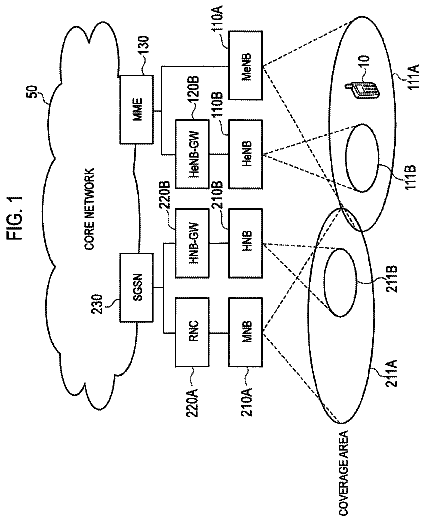
FIG. 1 illustrates a wireless communication system.
FIG. 2 illustrates a structure of a radio frame according to frequency division duplex (FDD) in 3rd generation partnership project (3GPP) long term evolution (LTE).
FIG. 3 illustrates a resource grid for a single uplink or downlink slot in 3GPP LTE.
FIG. 4 illustrates a structure of a downlink subframe.
FIG. 5 illustrates a structure of an uplink subframe in 3GPP LTE.
FIG. 6 illustrates an example of comparison between a single carrier system and a carrier aggregation system.
FIG. 7 illustrates cross-carrier scheduling in the carrier aggregation system.
FIG. 8 illustrates an example of monitoring a physical downlink control channel (PDCCH).
FIG. 9 illustrates an arrangement of a reference signal and a control channel in a downlink (DL) subframe of 3GPP LTE.
FIG. 10 illustrates a subframe having an enhanced PDCCH (EPDCCH).
FIG. 11 illustrates a structure of a PRB pair.
FIG. 12 illustrates examples of localized transmission and distributed transmission.
FIG. 13 illustrates an example of RE mapping for a DMRS.
FIG. 14 illustrates a change in a DMRS pattern
FIG. 15 is a flowchart illustrating a method for a DMRS pattern change according to a first embodiment of the present specification.
FIG. 16 is a flowchart illustrating a method for solving an imbalance between REs including a DMRS according to a second embodiment of the present specification.
FIG. 17 is a block diagram illustrating a wireless communication system according to one embodiment of the present specification.
Description of exemplary embodiments
Hereinafter, based on 3rd Generation Partnership Project (3GPP) long term evolution (LTE) or 3GPP LTE-advanced (LTE-A), the present invention will be applied. This is just an example, and the present invention may be applied to various wireless communication systems. Hereinafter, LTE includes LTE and/or LTE-A.
The technical terms used herein are used to merely describe specific embodiments and should not be construed as limiting the present invention. Further, the technical terms used herein should be, unless defined otherwise, interpreted as having meanings generally understood by those skilled in the art but not too broadly or too narrowly. Further, the technical terms used herein, which are determined not to exactly represent the spirit of the invention, should be replaced by or understood by such technical terms as being able to be exactly understood by those skilled in the art. Further, the general terms used herein should be interpreted in the context as defined in the dictionary, but not in an excessively narrowed manner.
The expression of the singular number in the specification includes the meaning of the plural number unless the meaning of the singular number is definitely different from that of the plural number in the context. In the following description, the term ‘include’ or ‘have’ may represent the existence of a feature, a number, a step, an operation, a component, a part or the combination thereof described in the specification, and may not exclude the existence or addition of another feature, another number, another step, another operation, another component, another part or the combination thereof.
The terms ‘first’ and ‘second’ are used for the purpose of explanation about various components, and the components are not limited to the terms ‘first’ and ‘second.’ The terms ‘first’ and ‘second’ are only used to distinguish one component from another component. For example, a first component may be named as a second component without deviating from the scope of the present invention.
It will be understood that when an element or layer is referred to as being “connected to” or “coupled to” another element or layer, it can be directly connected or coupled to the other element or layer or intervening elements or layers may be present. In contrast, when an element is referred to as being “directly connected to” or “directly coupled to” another element or layer, there are no intervening elements or layers present.
Hereinafter, exemplary embodiments of the present invention will be described in greater detail with reference to the accompanying drawings. In describing the present invention, for ease of understanding, the same reference numerals are used to denote the same components throughout the drawings, and repetitive description on the same components will be omitted. Detailed description on well-known arts which are determined to make the gist of the invention unclear will be omitted. The accompanying drawings are provided to merely make the spirit of the invention readily understood, but not should be intended to be limiting of the invention. It should be understood that the spirit of the invention may be expanded to its modifications, replacements or equivalents in addition to what is shown in the drawings.
As used herein, ‘base station’ generally refers to a fixed station that communicates with a wireless device and may be denoted by other terms such as eNB (evolved-NodeB), BTS (base transceiver system), or access point.
As used herein, User Equipment (UE) may be stationary or mobile, and may be denoted by other terms such as device, wireless device, terminal, MS (mobile station), UT (user terminal), SS (subscriber station), MT (mobile terminal) and etc.
The wireless device may be served by a plurality of serving cells. Each serving cell may be defined as a downlink (DL) component carrier (CC) or a pair of the DL CC and an uplink (UP) CC.
The serving cell may be divided into a primary cell and a secondary cell. The primary cell is a cell which operates at a primary frequency, and performs an initial connection establishment process, starts a connection reestablishment process, or is designated as the primary cell during a handover process. The primary cell is also referred to as a reference cell. The secondary cell operates at a secondary frequency, may be set after an RRC (Radio Resource Control) connection is established, and may be used to provide an additional radio resource. At least one primary cell may be continuously set, and the secondary cell may be add/modified/cancelled by higher layer signaling (e.g., an RRC message).
A cell index (CI) of the primary cell may be fixed. For example, a lowest CI may be designated as the CI of the primary cell. Hereinafter, the CI of the primary cell is 0, and CIs of the secondary cell are sequentially allocated from 1.
FIG. 1 illustrates a wireless communication system.
The wireless communication system includes at least one base station (BS) 20 . Respective BSs 20 provide a communication service to particular geographical areas 20 a , 20 b , and 20 c (which are generally called cells). Each cell may be divided into a plurality of areas (which are called sectors). User equipment (UE) 10 may be fixed or mobile and may be referred to by other names such as terminal, mobile station (MS), mobile user equipment (MT), user equipment (UT), subscriber station (SS), wireless device, personal digital assistant (PDA), wireless modem, handheld device. The BS 20 generally refers to a fixed station that communicates with the UE 10 and may be called by other names such as evolved-NodeB (eNB), base transceiver system (BTS), access point (AP), etc.
The UE generally belongs to one cell and the cell to which the UE belongs is referred to as a serving cell. A base station that provides the communication service to the serving cell is referred to as a serving BS. Since the wireless communication system is a cellular system, another cell that neighbors to the serving cell is present. Another cell which neighbors to the serving cell is referred to a neighbor cell. A base station that provides the communication service to the neighbor cell is referred to as a neighbor BS. The serving cell and the neighbor cell are relatively decided based on the UE.
Hereinafter, a downlink means communication from the base station 20 to the UE 10 and an uplink means communication from the UE 10 to the base station 20 . In the downlink, a transmitter may be a part of the base station 20 and a receiver may be a part of the UE 10 . In the uplink, the transmitter may be a part of the UE 10 and the receiver may be a part of the base station 20 .
Meanwhile, the wireless communication system may be any one of a multiple-input multiple-output (MIMO) system, a multiple-input single-output (MISO) system, a single-input single-output (SISO) system, and a single-input multiple-output (SIMO) system. The MIMO system uses a plurality of transmit antennas and a plurality of receive antennas. The MISO system uses a plurality of transmit antennas and one receive antenna. The SISO system uses one transmit antenna and one receive antenna. The SIMO system uses one transmit antenna and one receive antenna. Hereinafter, the transmit antenna means a physical or logical antenna used to transmit one signal or stream and the receive antenna means a physical or logical antenna used to receive one signal or stream.
Meanwhile, the wireless communication system may be generally divided into a frequency division duplex (FDD) type and a time division duplex (TDD) type. According to the FDD type, uplink transmission and downlink transmission are achieved while occupying different frequency bands. According to the TDD type, the uplink transmission and the downlink transmission are achieved at different time while occupying the same frequency band. A channel response of the TDD type is substantially reciprocal. This means that a downlink channel response and an uplink channel response are approximately the same as each other in a given frequency area. Accordingly, in the TDD based wireless communication system, the downlink channel response may be acquired from the uplink channel response. In the TDD type, since an entire frequency band is time-divided in the uplink transmission and the downlink transmission, the downlink transmission by the base station and the uplink transmission by the terminal may not be performed simultaneously. In the TDD system in which the uplink transmission and the downlink transmission are divided by the unit of a subframe, the uplink transmission and the downlink transmission are performed in different subframes.
Hereinafter, the LTE system will be described in detail.
FIG. 2 illustrates a structure of a radio frame according to FDD in 3rd generation partnership project (3GPP) long term evolution (LTE).
The section 5 of 3GPP TS 36.211 V8.2.0 (2008-03) “Evolved Universal Terrestrial Radio Access (E-UTRA); Physical Channels and Modulation (Release 8)” may be incorporated herein.
Referring to FIG. 2 , the radio frame is composed of ten subframes, and one subframe is composed of two slots. The slots in the radio frame are designated by slot numbers from 0 to 19. The time at which one subframe is transmitted is referred to as a transmission time interval (TTI). The TTI may be called as a scheduling unit for data transmission. For example, the length of one radio frame may be 10 ms, the length of one subframe may be 1 ms, and the length of one slot may be 0.5 ms.
The structure of the radio frame is merely an example, and the number of subframes included in the radio frame, the number of slots included in the subframe, etc. may be variously modified.
Although it is described that one slot includes plural OFDM symbols for example, the number of OFDM symbols included in one slot may vary depending on a length of a cyclic prefix (CP).
FIG. 3 illustrates a resource grid for a single uplink or downlink slot in 3GPP LTE.
Referring to FIG. 3 , the uplink slot includes a plurality of OFDM (orthogonal frequency division multiplexing) symbols in the time domain and NRB resource blocks (RBs) in the frequency domain. For example, in the LTE system, the number of resource blocks (RBs), i.e., NRB, may be one from 6 to 110.
Here, by way of example, one resource block includes 7×12 resource elements that consist of seven OFDM symbols in the time domain and 12 sub-carriers in the frequency domain. However, the number of sub-carriers in the resource block and the number of OFDM symbols are not limited thereto. The number of OFDM symbols in the resource block or the number of sub-carriers may be changed variously. In other words, the number of OFDM symbols may be varied depending on the above-described length of CP. In particular, 3GPP LTE defines one slot as having seven OFDM symbols in the case of CP and six OFDM symbols in the case of extended CP.
OFDM symbol is to represent one symbol period, and depending on system, may also be denoted SC-FDMA symbol, OFDM symbol, or symbol period. The resource block is a unit of resource allocation and includes a plurality of sub-carriers in the frequency domain. The number of resource blocks included in the uplink slot, i.e., NUL, is dependent upon an uplink transmission bandwidth set in a cell. Each element on the resource grid is denoted resource element.
Meanwhile, the number of sub-carriers in one OFDM symbol may be one of 128, 256, 512, 1024, 1536, and 2048.
In 3GPP LTE, the resource grid for one uplink slot shown in FIG. 3 may also apply to the resource grid for the downlink slot.
FIG. 4 illustrates a structure of a downlink subframe.
For this, 3GPP TS 36.211 V10.4.0 (2011-12) “Evolved Universal Terrestrial Radio Access (E-UTRA); Physical Channels and Modulation (Release 10)”, Ch. 4 may be referenced.
The radio frame includes 10 sub-frames indexed 0 to 9. One sub-frame includes two consecutive slots. Accordingly, the radio frame includes 20 slots. The time taken for one sub-frame to be transmitted is denoted TTI (transmission time interval). For example, the length of one sub-frame may be 1 ms, and the length of one slot may be 0.5 ms.
One slot may include a plurality of OFDM (orthogonal frequency division multiplexing) symbols in the time domain. OFDM symbol is merely to represent one symbol period in the time domain since 3GPP LTE adopts OFDMA (orthogonal frequency division multiple access) for downlink (DL), and the multiple access scheme or name is not limited thereto. For example, the OFDM symbol may be referred to as SC-FDMA (single carrier-frequency division multiple access) symbol or symbol period.
In FIG. 4 , assuming the normal CP, one slot includes seven OFDM symbols, by way of example. However, the number of OFDM symbols included in one slot may vary depending on the length of CP (cyclic prefix). That is, as described above, according to 3GPP TS 36.211 V10.4.0, one slot includes seven OFDM symbols in the normal CP and six OFDM symbols in the extended CP.
Resource block (RB) is a unit for resource allocation and includes a plurality of sub-carriers in one slot. For example, if one slot includes seven OFDM symbols in the time domain and the resource block includes 12 sub-carriers in the frequency domain, one resource block may include 7×12 resource elements (REs).
The DL (downlink) sub-frame is split into a control region and a data region in the time domain. The control region includes up to first three OFDM symbols in the first slot of the sub-frame. However, the number of OFDM symbols included in the control region may be changed. A PDCCH (physical downlink control channel) and other control channels are assigned to the control region, and a PDSCH is assigned to the data region.
As set forth in 3GPP TS 36.211 V10.4.0, the physical channels in 3GPP LTE may be classified into data channels such as PDSCH (physical downlink shared channel) and PUSCH (physical uplink shared channel) and control channels such as PDCCH (physical downlink control channel), PCFICH (physical control format indicator channel), PHICH (physical hybrid-ARQ indicator channel) and PUCCH (physical uplink control channel).
The PCFICH transmitted in the first OFDM symbol of the sub-frame carries CIF (control format indicator) regarding the number (i.e., size of the control region) of OFDM symbols used for transmission of control channels in the sub-frame. The wireless device first receives the CIF on the PCFICH and then monitors the PDCCH.
Unlike the PDCCH, the PCFICH is transmitted through a fixed PCFICH resource in the sub-frame without using blind decoding.
The PHICH carries an ACK (positive-acknowledgement)/NACK (negative-acknowledgement) signal for a UL HARQ (hybrid automatic repeat request). The ACK/NACK signal for UL (uplink) data on the PUSCH transmitted by the wireless device is sent on the PHICH.
The PBCH (physical broadcast channel) is transmitted in the first four OFDM symbols in the second slot of the first sub-frame of the radio frame. The PBCH carries system information necessary for the wireless device to communicate with the base station, and the system information transmitted through the PBCH is denoted MIB (master information block). In comparison, system information transmitted on the PDSCH indicated by the PDCCH is denoted SIB (system information block).
The PDCCH may carry activation of VoIP (voice over internet protocol) and a set of transmission power control commands for individual UEs in some UE group, resource allocation of an higher layer control message such as a random access response transmitted on the PDSCH, system information on DL-SCH, paging information on PCH, resource allocation information of UL-SCH (uplink shared channel), and resource allocation and transmission format of DL-SCH (downlink-shared channel). A plurality of PDCCHs may be sent in the control region, and the terminal may monitor the plurality of PDCCHs. The PDCCH is transmitted on one CCE (control channel element) or aggregation of some consecutive CCEs. The CCE is a logical allocation unit used for providing a coding rate per radio channel's state to the PDCCH. The CCE corresponds to a plurality of resource element groups. Depending on the relationship between the number of CCEs and coding rates provided by the CCEs, the format of the PDCCH and the possible number of PDCCHs are determined.
The control information transmitted through the PDCCH is denoted downlink control information (DCI). The DCI may include resource allocation of PDSCH (this is also referred to as DL (downlink) grant), resource allocation of PUSCH (this is also referred to as UL (uplink) grant), a set of transmission power control commands for individual UEs in some UE group, and/or activation of VoIP (Voice over Internet Protocol).
The base station determines a PDCCH format according to the DCI to be sent to the terminal and adds a CRC (cyclic redundancy check) to control information. The CRC is masked with a unique identifier (RNTI; radio network temporary identifier) depending on the owner or purpose of the PDCCH. In case the PDCCH is for a specific terminal, the terminal's unique identifier, such as C-RNTI (cell-RNTI), may be masked to the CRC. Or, if the PDCCH is for a paging message, a paging indicator, for example, P-RNTI (paging-RNTI) may be masked to the CRC. If the PDCCH is for a system information block (SIB), a system information identifier, SI-RNTI (system information-RNTI), may be masked to the CRC. In order to indicate a random access response that is a response to the terminal's transmission of a random access preamble, an RA-RNTI (random access-RNTI) may be masked to the CRC.
In 3GPP LTE, blind decoding is used for detecting a PDCCH. The blind decoding is a scheme of identifying whether a PDCCH is its own control channel by demasking a desired identifier to the CRC (cyclic redundancy check) of a received PDCCH (this is referred to as candidate PDCCH) and checking a CRC error. The base station determines a PDCCH format according to the DCI to be sent to the wireless device, then adds a CRC to the DCI, and masks a unique identifier (this is referred to as RNTI (radio network temporary identifier) to the CRC depending on the owner or purpose of the PDCCH.
According to 3GPP TS 36.211 V10.4.0, the uplink channels include a PUSCH, a PUCCH, an SRS (Sounding Reference Signal), and a PRACH (physical random access channel).
FIG. 5 illustrates a structure of an uplink subframe in 3GPP LTE.
Referring to FIG. 5 , the uplink sub-frame may be separated into a control region and a data region in the frequency domain. The control region is assigned a PUCCH (physical uplink control channel) for transmission of uplink control information. The data region is assigned a PUSCH (physical uplink shared channel) for transmission of data (in some cases, control information may also be transmitted).
The PUCCH for one terminal is assigned in resource block (RB) pair in the sub-frame. The resource blocks in the resource block pair take up different sub-carriers in each of the first and second slots. The frequency occupied by the resource blocks in the resource block pair assigned to the PUCCH is varied with respect to a slot boundary. This is referred to as the RB pair assigned to the PUCCH having been frequency-hopped at the slot boundary.
The terminal may obtain a frequency diversity gain by transmitting uplink control information through different sub-carriers over time. m is a location index that indicates a logical frequency domain location of a resource block pair assigned to the PUCCH in the sub-frame.
The uplink control information transmitted on the PUCCH includes an HARQ (hybrid automatic repeat request), an ACK (acknowledgement)/NACK (non-acknowledgement), a CQI (channel quality indicator) indicating a downlink channel state, and an SR (scheduling request) that is an uplink radio resource allocation request.
The PUSCH is mapped with a UL-SCH that is a transport channel. The uplink data transmitted on the PUSCH may be a transport block that is a data block for the UL-SCH transmitted for the TTI. The transport block may be user information. Or, the uplink data may be multiplexed data. The multiplexed data may be data obtained by multiplexing the transport block for the UL-SCH and control information. For example, the control information multiplexed with the data may include a CQI, a PMI (precoding matrix indicator), an HARQ, and an RI (rank indicator). Or, the uplink data may consist only of control information.
A carrier aggregation system is now described.
FIG. 6 illustrates an example of comparison between a single carrier system and a carrier aggregation system.
Referring to FIG. 6 , there may be various carrier bandwidths, and one carrier is assigned to the terminal. On the contrary, in the carrier aggregation (CA) system, a plurality of component carriers (DL CC A to C, UL CC A to C) may be assigned to the terminal. Component carrier (CC) means the carrier used in then carrier aggregation system and may be briefly referred as carrier. For example, three 20 MHz component carriers may be assigned so as to allocate a 60 MHz bandwidth to the terminal.
Carrier aggregation systems may be classified into a contiguous carrier aggregation system in which aggregated carriers are contiguous and a non-contiguous carrier aggregation system in which aggregated carriers are spaced apart from each other. Hereinafter, when simply referring to a carrier aggregation system, it should be understood as including both the case where the component carrier is contiguous and the case where the control channel is non-contiguous.
When one or more component carriers are aggregated, the component carriers may use the bandwidth adopted in the existing system for backward compatibility with the existing system. For example, the 3GPP LTE system supports bandwidths of 1.4 MHz, 3 MHz, 5 MHz, 10 MHz, 15 MHz and 20 MHz, and the 3GPP LTE-A system may configure a broad band of 20 MHz or more only using the bandwidths of the 3GPP LTE system. Or, rather than using the bandwidths of the existing system, new bandwidths may be defined to configure a wide band.
The system frequency band of a wireless communication system is separated into a plurality of carrier frequencies. Here, the carrier frequency means the cell frequency of a cell. Hereinafter, the cell may mean a downlink frequency resource and an uplink frequency resource. Or, the cell may refer to a combination of a downlink frequency resource and an optional uplink frequency resource. Further, in the general case where carrier aggregation (CA) is not in consideration, one cell may always have a pair of an uplink frequency resource and a downlink frequency resource.
In order for packet data to be transmitted/received through a specific cell, the terminal should first complete a configuration on the specific cell. Here, the configuration means that reception of system information necessary for data transmission/reception on a cell is complete. For example, the configuration may include an overall process of receiving common physical layer parameters or MAC (media access control) layers necessary for data transmission and reception or parameters necessary for a specific operation in the RRC layer. A configuration-complete cell is in the state where, once when receiving information indicating packet data may be transmitted, packet transmission and reception may be immediately possible.
The cell that is in the configuration complete state may be left in an activation or deactivation state. Here, the “activation” means that data transmission or reception is being conducted or is in ready state. The terminal may monitor or receive a control channel (PDCCH) and a data channel (PDSCH) of the activated cell in order to identify resources (possibly frequency or time) assigned thereto.
The “deactivation” means that transmission or reception of traffic data is impossible while measurement or transmission/reception of minimal information is possible. The terminal may receive system information (SI) necessary for receiving packets from the deactivated cell. In contrast, the terminal does not monitor or receive a control channel (PDCCH) and data channel (PDSCH) of the deactivated cell in order to identify resources (probably frequency or time) assigned thereto.
Cells may be classified into primary cells and secondary cells, serving cells.
The primary cell means a cell operating at a primary frequency. The primary cell is a cell where the terminal conducts an initial connection establishment procedure or connection re-establishment procedure with the base station or is a cell designated as a primary cell during the course of handover.
The secondary cell means a cell operating at a secondary frequency. The secondary cell is configured once an RRC connection is established and is used to provide an additional radio resource.
The serving cell is configured as a primary cell in case no carrier aggregation is configured or when the terminal cannot offer carrier aggregation. In case carrier aggregation is configured, the term “serving cell” denotes a cell configured to the terminal and a plurality of serving cells may be included. One serving cell may consist of one downlink component carrier or a pair of {downlink component carrier, uplink component carrier}. A plurality of serving cells may consist of a primary cell and one or more of all the secondary cells.
The PCC (primary component carrier) means a component carrier (CC) corresponding to the primary cell. The PCC is, among several CCs, the one where the terminal initially achieves connection or RRC connection with the base station. The PCC is a special CC that is in charge of connection or RRC connection for signaling regarding multiple CCs and manages terminal context information (UE context) that is connection information related with the terminal. Further, the PCC achieves connection with the terminal, so that the PCC is always left in the activation state when in RRC connected mode. The downlink component carrier corresponding to the primary cell is denoted downlink primary component carrier (DL PCC) and the uplink component carrier corresponding to the primary cell is denoted uplink primary component carrier (UL PCC).
The SCC (secondary component carrier) means a CC corresponding to a secondary cell. That is, the SCC is a CC other than the PCC, which is assigned to the terminal and is an extended carrier for the terminal to perform additional resource allocation in addition to the PCC. The SCC may be left in activation state or deactivation state. The downlink component carrier corresponding to the secondary cell is denoted downlink secondary component carrier (DL SCC) and the uplink component carrier corresponding to the secondary cell is denoted uplink secondary component carrier (UL SCC).
The primary cell and the secondary cell have the following characteristics.
First, the primary cell is used for transmitting a PUCCH. Second, the primary cell is always left activated while the secondary cell may be activated/deactivated depending on a specific condition. Third, when the primary cell experiences a radio link failure (hereinafter, ‘RLF’), RRC re-connection is triggered. Fourth, the primary cell may be varied by a handover procedure that comes with an RACH (random access channel) procedure or by altering a security key. Fifth, NAS (non-access stratum) information is received through the primary cell. Sixth, in the FDD system, the primary cell has always a pair of a DL PCC and a UL PCC. Seventh, a different component carrier (CC) may be set as a primary cell in each terminal. Eighth, the primary cell may be replaced only through a handover or cell selection/cell re-selection procedure. In adding a new serving cell, RRC signaling may be used to transmit system information of a dedicated serving cell.
When configuring a serving cell, a downlink component carrier may form one serving cell or a downlink component carrier and an uplink component carrier form a connection to thereby configure one serving cell. However, a serving cell is not configured with one uplink component carrier alone.
Activation/deactivation of a component carrier is equivalent in concept to activation/deactivation of a serving cell. For example, assuming that serving cell 1 is constituted of DL CC 1 , activation of serving cell 1 means activation of DL CC 1 . If serving cell 2 is configured by connection of DL CC 2 and UL CC 2 , activation of serving cell 2 means activation of DL CC 2 and UL CC 2 . In this sense, each component carrier may correspond to a serving cell.
The number of component carriers aggregated between uplink and downlink may vary. When the number of downlink CCs is the same as the number of uplink CCs is denoted symmetric aggregation, and when the numbers differ from each other is denoted asymmetric aggregation. Further, the sizes (i.e., bandwidth) of CCs may be different from each other. For example, when five CCs are used to configure a 70 MHz band, the configuration may be made as follows: 5 MHz CC(carrier #0)+20 MHz CC(carrier #1)+20 MHz CC(carrier #2)+20 MHz CC(carrier #3)+5 MHz CC(carrier #4).
As described above, the carrier aggregation system, unlike the single carrier system, may support a plurality of component carriers (CCs), i.e., a plurality of serving cells.
Such carrier aggregation system may support cross-carrier scheduling. The cross-carrier scheduling is a scheduling scheme that may conduct resource allocation of a PUSCH transmitted through other component carriers than the component carrier basically linked to a specific component carrier and/or resource allocation of a PDSCH transmitted through other component carriers through a PDCCH transmitted through the specific component carrier. In other words, the PDCCH and the PDSCH may be transmitted through different downlink CCs, and the PUSCH may be transmitted through an uplink CC other than the uplink CC linked to the downlink CC where the PDCCH including a UL grant is transmitted. As such, the system supporting cross-carrier scheduling needs a carrier indicator indicating a DL CC/UL CC through which a PDSCH/PUSCH is transmitted where the PDCCH offers control information. The field including such carrier indicator is hereinafter denoted carrier indication field (CIF).
The carrier aggregation system supporting cross-carrier scheduling may contain a carrier indication field (CIF) in the conventional DCI (downlink control information) format. In the cross-carrier scheduling-supportive carrier aggregation system, for example, an LTE-A system, may have 3 bits expanded due to addition of the CIF to the existing DCI format (i.e., the DCI format used in the LTE system), and the PDCCH architecture may reuse the existing coding method or resource allocation method (i.e., CCE-based resource mapping).
FIG. 7 illustrates cross-carrier scheduling in the carrier aggregation system.
Referring to FIG. 7 , the base station may configure a PDCCH monitoring DL CC (monitoring CC) set. The PDCCH monitoring DL CC set consists of some of all of the aggregated DL CCs, and if cross-carrier scheduling is configured, the user equipment performs PDCCH monitoring/decoding only on the DL CCs included in the PDCCH monitoring DL CC set. In other words, the base station transmits a PDCCH for PDSCH/PUSCH that is subject to scheduling only through the DL CCs included in the PDCCH monitoring DL CC set. The PDCCH monitoring DL CC set may be configured UE-specifically, UE group-specifically, or cell-specifically.
FIG. 7 illustrates an example in which three DL CCs (DL CC A, DL CC B, and DL CC C) are aggregated, and DL CC A is set as a PDCCH monitoring DL CC. The user equipment may receive a DL grant for the PDSCH of DL CC A, DL CC B, and DL CC C through the PDCCH of DL CC A. The DCI transmitted through the PDCCH of DL CC A contains a CIF so that it may indicate which DL CC the DCI is for.
FIG. 8 illustrates an example of monitoring a PDCCH.
The section 9 of 3GPP TS 36.213 V10.2.0 (2011-06) can be incorporated herein by reference.
The 3GPP LTE uses blind decoding for PDCCH detection. The blind decoding is a scheme in which a desired identifier is de-masked from a CRC of a received PDCCH (referred to as a candidate PDCCH) to determine whether the PDCCH is its own control channel by performing CRC error checking. A wireless device cannot know about a specific position in a control region in which its PDCCH is transmitted and about a specific CCE aggregation or DCI format used for PDCCH transmission.
A plurality of PDCCHs can be transmitted in one subframe. The wireless device monitors the plurality of PDCCHs in every subframe. Monitoring is an operation of attempting PDCCH decoding by the wireless device according to a format of the monitored PDCCH.
The 3GPP LTE uses a search space to reduce a load of blind decoding. The search space can also be called a monitoring set of a CCE for the PDCCH. The wireless device monitors the PDCCH in the search space.
The description continues in the full USPTO document.
 Lapsed, fee not paid12 drawings

