Lapsed, fee not paid12 drawings
Hardware & Electronics · US 9,762,015 B2
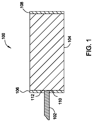
Brush holder apparatus and system
A brush holder system includes a stationary support member having at least one groove, and a fork electrical connector.
US 9,762,034 B2 · Assignee: FUJITSU LIMITED · Inventors: Takabayashi; Kazumasa et al.
Sheet 1 of 14 from the published document. All sheets in the USPTO PDF
A tunable laser source includes a mirror, a tunable filter, and a semiconductor optical amplifier integrated device including first, second, and third semiconductor optical amplifiers between a first end face facing toward the tunable filter and a second end face facing away from the first end face. The first amplifier is closer to the first end face than the second and third amplifiers. The semiconductor optical amplifier integrated device further includes a partially reflecting mirror and an optical divider that are disposed between the first amplifier and the second and third amplifiers. The partially reflecting mirror is closer to the first amplifier than the optical divider. The optical divider includes first and second branches connected to the second and third semiconductor optical amplifiers, respectively. The tunable filter and the first amplifier are disposed in an optical path between the partially reflecting mirror and the mirror that form a laser resonator.
Wavelength multiplexing optical communications systems using coherent modulation such as dual polarization quadrature phase shift keying (DP-QPSK) have been introduced to address an increase in transmission capacity in optical communications. According to DP-QPSK, the transmission capacity per wavelength is 100 Gb/s. To further increase the transmission capacity, a study has been made of optical transmission using coherent modulation techniques capable of transmitting a large amount of information, such as 16 quadrature amplitude modulation (16QAM). Such coherent modulation techniques capable of transmitting a large amount of information require a spectral linewidth that indicates the amount of wavelength fluctuation of a laser beam emitted from a light source to be narrow. For example, 16QAM requires a spectral linewidth of 100 kHz or less. For example, as a tunable laser source of a na
1 of 14 drawing sheets so far from the published document, cropped to the drawing. Every sheet is in the USPTO PDF.
What the patent claimed, word for word. All of it is now free to use.
A certain aspect of the embodiments discussed herein is related to tunable laser sources, optical transmitters, and optical transmitter and receiver modules.
Wavelength multiplexing optical communications systems using coherent modulation such as dual polarization quadrature phase shift keying (DP-QPSK) have been introduced to address an increase in transmission capacity in optical communications. According to DP-QPSK, the transmission capacity per wavelength is 100 Gb/s. To further increase the transmission capacity, a study has been made of optical transmission using coherent modulation techniques capable of transmitting a large amount of information, such as 16 quadrature amplitude modulation (16QAM).
Such coherent modulation techniques capable of transmitting a large amount of information require a spectral linewidth that indicates the amount of wavelength fluctuation of a laser beam emitted from a light source to be narrow. For example, 16QAM requires a spectral linewidth of 100 kHz or less. For example, as a tunable laser source of a narrow linewidth, an external-cavity laser source as depicted in FIG. 1 is proposed (see, for example, International Publication Pamphlet No. WO2007/080891). This external-cavity laser source is a combination of a semiconductor optical amplifier (SOA) 910 that serves as a gain medium, a lens 921 , a tunable filter 922 , and an external mirror 923 . According to the external-cavity laser source structured as described above, an anti-reflective (AR) coating 911 is provided on one end face 910 a of the SOA 910 , and a partially reflective coating 912 is provided on the other end face 910 b of the SOA 910 .
Accordingly, a laser resonator (cavity) is formed by the partially reflective coating 912 provided on the other end face 910 b and the external mirror 923 , and the lens 921 and the tunable filter 922 are disposed in the optical path between the SOA 910 and the external mirror 923 . According to this tunable laser source, a laser beam is emitted from the side of the other end face 910 b of the SOA 910 on which the partially reflective coating 912 is provided. The spectral linewidth of the emitted laser beam tends to be narrower as the laser resonator becomes longer. External-cavity laser sources, for which it is easy to increase the length of the laser resonator, are suitable to reduce the spectral linewidth and have achieved spectral linewidths of 100 kHz or less.
Furthermore, according to coherent modulation, input signal light input to a receiver that serves as a coherent receiver and local oscillation light having an oscillation wavelength close to the wavelength of the input signal light are caused to interfere with each other to detect a phase modulation signal. Therefore, optical transmitter and receiver modules adopting coherent modulation employ two laser sources, namely, a laser source for output signal light and a laser source for local oscillation light. Specifically, as depicted in FIG. 2 , according to optical transmitter and receiver modules adopting coherent modulation, a laser source 931 is provided in a transmitter 930 , and a laser source 941 is provided in a receiver 940 . A laser beam emitted from the laser source 931 is modulated in a DP-QPSK modulator 932 to be output from the transmitter 930 as an output signal. Furthermore, an input signal input to the receiver 940 , together with local oscillation light emitted from the laser source 941 , enters a hybrid 942 , and light exiting from the hybrid 942 is detected at a light-receiving element 943 . The coherent-modulation optical transmitter and receiver module having a structure as depicted in FIG. 2 , however, requires two laser sources, and accordingly, is large in size. Therefore, there is a demand for coherent-modulation optical transmitter and receiver modules that are reduced in size.
From such a viewpoint, a coherent-modulation optical transmitter and receiver module using a single laser beam as depicted in FIG. 3 is proposed (see, for example, Japanese Laid-open Patent Publication No. 2007-64860). According to the coherent-modulation optical transmitter and receiver module as depicted in FIG. 3 , a laser beam emitted from the laser source 931 is split into signal light and local oscillation light by a beam splitter 933 . Specifically, of the laser beam emitted from the laser source 931 to be incident on the beam splitter 933 , a part transmitted through the beam splitter 933 becomes signal light, which enters the DP-QPSK modulator 932 to be modulated and is output from the transmitter 930 as an output signal, and a part reflected by the beam splitter 933 becomes local oscillation light, which, together with an input signal input to the receiver 940 , enters the hybrid 942 . Light exiting from the hybrid 942 is detected at the light-receiving element 943 .
Thus, the coherent-modulation optical transmitter and receiver module depicted in FIG. 3 does not require the laser source 941 provided in the receiver 940 of the coherent-modulation optical transmitter and receiver module depicted in FIG. 2 , and accordingly, can be reduced in size. According to the coherent-modulation optical transmitter and receiver module depicted in FIG. 3 , however, the single laser source 931 is required to emit a laser beam that becomes both signal light and local oscillation light, and accordingly, is required to be capable of emitting a high-power laser beam.
As a laser source capable of emitting a high-power laser beam, a laser source that further includes an SOA provided in the stage subsequent to a laser resonator is proposed (see, for example, International Publication Pamphlet No. WO2007/080891). As depicted in FIG. 4 , this laser source is a combination of an SOA integrated device 950 , the lens 921 , the tunable filter 922 , and the external mirror 923 . The SOA integrated device 950 includes a first SOA 951 , a second SOA 952 , and a partially reflecting mirror 953 formed between the first and second SOAs 951 and 952 . Furthermore, an AR coating 954 is provided on one end face 950 a of the SOA integrated device 950 on the external cavity side, and an AR coating 955 is provided on the other end face 950 b of the SOA integrated device 950 through which a laser beam is emitted.
According to the laser source having the above-described structure, a laser resonator is formed by the partially reflecting mirror 953 of the SOA integrated device 950 and the external mirror 923 . The lens 921 , the tunable filter 922 , and the first SOA 951 are disposed in the optical path between the partially reflecting mirror 953 and the external mirror 923 . A laser beam transmitted through the partially reflecting mirror 953 is amplified by the second SOA 952 serving as an amplifier. Accordingly, the laser source having the above-described structure can emit a high-power laser beam.
According to an aspect of the embodiments, a tunable laser source includes a mirror, a tunable filter, and a semiconductor optical amplifier integrated device including first, second, and third semiconductor optical amplifiers between a first end face facing toward the tunable filter and a second end face facing away from the first end face. The first amplifier is closer to the first end face than the second and third amplifiers. The semiconductor optical amplifier integrated device further includes a partially reflecting mirror and an optical divider that are disposed between the first amplifier and the second and third amplifiers. The partially reflecting mirror is closer to the first amplifier than the optical divider. The optical divider includes first and second branches connected to the second and third semiconductor optical amplifiers, respectively. The tunable filter and the first amplifier are disposed in an optical path between the partially reflecting mirror and the mirror that form a laser resonator.
The object and advantages of the embodiments will be realized and attained by means of the elements and combinations particularly pointed out in the claims.
It is to be understood that both the foregoing general description and the following detailed description are exemplary and explanatory and not restrictive of the invention.
FIG. 1 is a diagram depicting a structure of a laser source of an external-cavity laser;
FIG. 2 is a diagram depicting a structure of an optical transmitter and receiver module for coherent communications;
FIG. 3 is a diagram depicting a structure of an optical transmitter and receiver module for coherent communications;
FIG. 4 is a diagram depicting a structure of a laser source of an external-cavity laser;
FIG. 5 is a diagram depicting a tunable laser source according to a first embodiment;
FIGS. 6A and 6B are diagrams depicting SOA integrated devices;
FIG. 7 is a graph representing the relationship between the reflectance of an end face and the spectral linewidth of a laser beam in the SOA integrated devices;
FIG. 8 is a diagram depicting the tunable laser source according to the first embodiment;
FIG. 9 is a plan view of the SOA integrated device according to the first embodiment;
FIG. 10 is a cross-sectional view of the SOA integrated device according to the first embodiment;
FIGS. 11A through 11D are cross-sectional views of the SOA integrated device according to the first embodiment;
FIG. 12 is a diagram depicting a first variation of the SOA integrated device according to the first embodiment;
FIG. 13 is a diagram depicting a second variation of the SOA integrated device according to the first embodiment;
FIG. 14 is a plan view of an SOA integrated device according to a second embodiment;
FIG. 15 is a cross-sectional view of the SOA integrated device according to a second embodiment;
FIG. 16 is a diagram depicting a structure of an optical transmitter and receiver module according to a third embodiment;
FIGS. 17A and 17B are diagrams depicting a tunable laser source according to a fourth embodiment;
FIGS. 18A and 18B are diagrams depicting a tunable laser source according to a fifth embodiment; and
FIG. 19 is a diagram depicting a tunable laser source configured to produce three optical outputs according to an embodiment.
According to the tunable laser source having the structure as depicted in FIG. 4 , when there is residual reflection at the AR coating 955 provided on the other end face 950 b , light reflected and returning from the AR coating 955 (returning light) is amplified by the second SOA 952 to enter the laser resonator. There is a general tendency that as the returning light reflected from the AR coating 955 increases, the laser oscillation condition is disturbed to increase the spectral linewidth. Accordingly, as the amplification factor of the second SOA 952 increases to increase the output power of the laser beam, the spectral linewidth of the laser beam increases. That is, according to the laser source having the structure as depicted in FIG. 4 , there is a tradeoff between increasing the output power of the laser beam and narrowing the spectral linewidth of the laser beam, so that it is difficult to increase the output power of the laser beam with the spectral linewidth of the laser beam being narrow.
Furthermore, according to optical transmitter and receiver modules, it is preferable to control the output of a laser beam for output signal light and the output of a laser beam for local oscillation light independent of each other. In the case depicted in FIG. 3 , however, where the laser beam emitted from the laser source 931 is split into partial laser beams, it is impossible to control the outputs of the partial laser beams independent of each other. Furthermore, in the case of splitting the laser beam in a desired ratio, an attenuator is disposed in the optical path of one of the partial laser beams to attenuate the output power of the one of the partial laser beams. In the case of attenuating a laser beam, however, the required output power of the laser beam emitted from a laser source is increased by the amount to be attenuated. Accordingly, in the case of employing the laser source having the structure as depicted in FIG. 4 , the amplification factor of the second SOA 952 is increased. Increasing the amplification factor, however, causes the returning light to exert a significant influence, thus increasing the spectral linewidth.
Therefore, there is a demand for tunable laser sources capable of emitting a high-power laser beam having a narrow spectral linewidth.
According to an aspect of the present invention, a tunable laser source is capable of emitting a high-power laser beam having a narrow spectral linewidth.
Preferred embodiments of the present invention will be explained with reference to accompanying drawings. The same element is referred to using the same reference numeral, and a repetitive description thereof is omitted. [a] First Embodiment
A tunable laser source according to a first embodiment is described with reference to FIG. 5 . Referring to FIG. 5 , the tunable laser source of this embodiment includes an SOA integrated device 10 , a lens 51 , a tunable filter 52 , and an external mirror 53 .
The SOA integrated device 10 includes a first SOA 11 , a second SOA 12 , a third SOA 13 , a partially reflecting mirror 14 , and an optical divider 15 . The partially reflecting mirror 14 and the optical divider 15 are provided between the first SOA 11 and the second and third SOAs 12 and 13 . An AR coating 16 is provided on a first end face 10 a of the SOA integrated device 10 . An AR coating 17 is provided on a second end face 10 b of the SOA integrated device 10 . That is, in the SOA integrated device 10 , the AR coating 16 is provided on the first end face 10 a on the side of which the first SOA 11 is formed, and the AR coating 17 is provided on the second end face 10 b on the side of which the second SOA 12 and the third SOA 13 are formed.
The partially reflecting mirror 14 of the SOA integrated device 10 and the external mirror 53 form the laser resonator (cavity) of the tunable laser source of this embodiment. The lens 51 , the tunable filter 52 , and the first SOA 11 are disposed in the optical path between the partially reflecting mirror 14 and the external mirror 53 . Part of a laser beam oscillated in the laser resonator including the first SOA 11 exits from the first SOA 11 to be transmitted through the partially reflecting mirror 14 to be incident on the optical divider 15 . The optical divider 15 is a 1×2 multi-mode interference (MMI) splitter, and includes two branches, of which one connects to the second SOA 12 and the other connects to the third SOA 13 , so that the laser beam incident on the optical divider 15 is branched (divided) into two laser beams. Of the two laser beams into which the laser beam is thus branched in the optical divider 15 and which exit from the optical divider 15 , one enters the second SOA 12 and the other enters the third SOA 13 .
The laser beam entering the second SOA 12 is amplified as desired in the second SOA 12 to be emitted from the second end face 10 b of the SOA integrated device 10 through the AR coating 17 as signal light. The laser beam entering the third SOA 13 is amplified as desired in the third SOA 13 to be emitted from the second end face 10 b of the SOA integrated device 10 through the AR coating 17 as local oscillation light.
Compared with the tunable laser source depicted in FIG. 4 , the tunable laser source of this embodiment can reduce the influence of the returning light by half on average, and accordingly, can reduce an increase in the spectral linewidth due to the returning light. This is described in more detail with reference to FIGS. 6A, 6B and 7 . FIG. 6A depicts the case of the SOA integrated device 950 of the tunable laser source depicted in FIG. 4 . According to the SOA integrated device 950 , a laser beam generated in the laser resonator formed by the external mirror 923 ( FIG. 4 ) and the partially reflecting mirror 953 enters the second SOA 952 through the partially reflecting mirror 953 . Here, it is assumed that the power of the laser beam entering the second SOA 952 through the partially reflecting mirror 953 be P 0 . According to this tunable laser source, in order to obtain the power P of signal light and the power P of local oscillation light, the power of the laser beam emitted from the SOA integrated device 950 through the AR coating 955 is required to be 2P. Therefore, the amplification factor of the second SOA 952 is 2P/P 0 . Furthermore, as described above, the AR coating 955 in the SOA integrated device 950 is difficult to make completely free of reflection, and slightly reflects light. It is assumed that the reflectance of the AR coating 955 is R. The returning light reflected from the AR coating 955 is amplified by the second SOA 952 to be incident on the partially reflecting mirror 953 .
Accordingly, the power of the returning light incident on the partially reflecting mirror 953 is given by (the power of the laser beam entering the second SOA 952 )×(the amplification factor of the second SOA 952 )× (the reflectance of the AR coating 955 )×(the amplification factor of the second SOA 952 ), namely, P 0 × (2P/P 0 )× R× (2P/P 0 )=4RP.sup.2/P 0 . That is, according to the SOA integrated device 950 depicted in FIG. 6A , a laser beam whose power is 4RP.sup.2/P 0 is made incident on the partially reflecting mirror 953 as returning light. The laser beam thus returning to be incident on the partially reflecting mirror 953 is transmitted at a predetermined transmittance to enter the laser resonator to be amplified.
FIG. 6B depicts the case of the SOA integrated device 10 of the tunable laser source of this embodiment as depicted in FIG. 5 . According to the SOA integrated device 10 , a laser beam generated in the laser resonator formed by the external mirror 53 ( FIG. 5 ) and the partially reflecting mirror 14 enters the optical divider 15 through the partially reflecting mirror 14 . Here, it is assumed that the power of the laser beam made incident on the optical divider 15 through the partially reflecting mirror 14 be P 0 . The laser beam of the power P 0 incident on the optical divider 15 is divided into laser beams (divisional laser beams) in a ratio of 1:1 in the optical divider 15 . Therefore, the divisional laser beams enter the second SOA 12 and the third SOA 13 each with a power of P 0 /2. Therefore, according to the tunable laser source of this embodiment, in order to obtain the power P of signal light and the power P of local oscillation light, the amplification factor of each of the second SOA 12 and the third SOA 13 is 2P/P 0 .
Letting the reflectance R of the AR coating 17 in the SOA integrated device 10 be R, the returning light from the AR coating 17 is amplified in the second SOA 12 and the third SOA 13 to be divided in a ratio of 1:1 in the optical divider 15 to be incident on the partially reflecting mirror 14 . Accordingly, the average power of the returning light is the total of the power of the returning light from the second SOA 12 and the power of the returning light from the third SOA 13 , given by (the power of the laser beam made incident on the optical divider 15 )×(the division ratio of the optical divider 15 )×(the amplification factor of the second SOA 12 or the third SOA 13 )×(the reflectance of the AR coating 17 )×(the amplification factor of the second SOA 12 or the third SOA 13 )×(the division ratio of the optical divider 15 )×(the number of SOAs). Specifically, the power of the returning light made incident on the partially reflecting mirror 14 is given by P 0 ×(1/2)×(2P/P 0 )×R×(1/2)×(2P/P 0 )×2=2RP.sup.2/P 0 . That is, according to the SOA integrated device 10 employed in the tunable laser source of this embodiment as depicted in FIG. 6B , a laser beam whose power is 2RP.sup.2/P 0 is made incident on the partially reflecting mirror 14 as returning light. The laser beam thus returning to be incident on the partially reflecting mirror 14 is transmitted at a predetermined transmittance to enter the laser resonator to be amplified. Therefore, according to the tunable laser source according to this embodiment, the power of the returning light entering the laser resonator can be half of that of the tunable laser source depicted in FIG. 4 . When the two returning light beams match in phase in the optical divider 15 , the power of the returning light may be substantially the same as in the case depicted in FIG. 6A , but otherwise, the power of the returning light is lower than in the case depicted in FIG. 6A . Therefore, the power of the returning light is substantially the same as in the case depicted in FIG. 6B on average.
Next, the relationship between the reflectance of an end face and the spectral linewidth of a laser beam is described with reference to FIG. 7 . Specifically, a description is given of the relationship between the reflectance of an end face and the spectral linewidth of a laser beam in the tunable laser source employing the SOA integrated device 950 depicted in FIG. 6A and the tunable laser source of this embodiment employing the SOA integrated device 10 depicted in FIG. 6B . FIG. 7 graphically represents results obtained by calculations. In FIG. 7 , the dashed line indicates a characteristic 7 A of the tunable laser source employing the SOA integrated device 950 depicted in FIG. 6A , and the solid line indicates a characteristic 7 B of the tunable laser source of this embodiment employing the SOA integrated device 10 depicted in FIG. 6B . The reflectance of an end face (“end face reflectance”) in FIG. 7 is the reflectance of an end face from which a laser beam is emitted. That is, the end face reflectance in FIG. 7 is the reflectance of the end face 950 b ( FIG. 4 ) on which the AR coating 955 is provided in the SOA integrated device 950 depicted in FIG. 6A and is the reflectance of the second end face 10 b ( FIG. 5 ) on which the AR coating 17 is provided in the SOA integrated device 10 depicted in FIG. 6B . Furthermore, in the calculations, the amplification factor of the second SOA 952 of the SOA integrated device 950 depicted in FIG. 6A is 10, and the amplification factor of each of the second SOA 12 and the third SOA 13 of the SOA integrated device 10 depicted in FIG. 6B is 10. In addition, in FIG. 7 , when an end face reflectance of 0, the spectral linewidth is normalized as 1.
Referring to FIG. 7 , when the end face reflectance is 0.05% (indicated by the one-dot chain line), the spectral linewidth of the tunable laser source employing the SOA integrated device 950 depicted in FIG. 6A is approximately three times that at an end face reflectance of 0 as indicated by the characteristic 7 A, while the spectral linewidth of the tunable laser source of this embodiment employing the SOA integrated device 10 depicted in FIG. 6B is approximately 1.5 times that at an end face reflectance of 0 as indicated by the characteristic 7 B. Accordingly, when the end face reflectance is 0.05%, the spectral linewidth of the tunable laser source of this embodiment employing the SOA integrated device 10 depicted in FIG. 6B is approximately half the spectral linewidth of the tunable laser source employing the SOA integrated device 950 depicted in FIG. 6A .
Next, the tunable laser source of this embodiment is described in more detail. FIG. 8 is a diagram depicting constituent parts or members of the tunable laser source of this embodiment almost in life size. The tunable laser source of this embodiment is a combination of the SOA integrated device 10 , the lens 51 , the tunable filter 52 , and the external mirror 53 .
According to this embodiment, as depicted in FIG. 8 , the tunable filter 52 includes two etalons that are minutely different in free spectral range (FSR) from each other, namely, a first etalon 52 a and a second etalon 52 b . The tunable filter 52 can variably tune to a desired wavelength because of the Vernier effect due to the combination of the first etalon 52 a and the second etalon 52 b . A beam of parallel rays is required to be incident on the first etalon 52 a and the second etalon 52 b in the tunable filter 52 . Therefore, a lens 51 such as a collimator lens is disposed between the tunable filter 52 and the SOA integrated device 10 . The tunable filter 52 and the lens 51 are disposed in the optical path between the external mirror 53 and the SOA integrated device 10 . The external mirror 53 can reflect light transmitted through the tunable filter 52 and cause the reflected light to re-enter the tunable filter 52 to return to the SOA integrated device 10 .
Referring to FIG. 9 , the SOA integrated device 10 includes the first SOA 11 , the second SOA 12 , and the third SOA 13 . The partially reflecting mirror 14 and the optical divider 15 are disposed between the first SOA 11 and the second and third SOAs 12 and 13 . The AR coating 16 is provided on the first end face 10 a of the SOA integrated device 10 . The AR coating 17 is provided on the second end face 10 b of the SOA integrated device 10 . That is, in the SOA integrated device 10 , the AR coating 16 is provided on the first end face 10 a on the side of which the first SOA 11 is formed, and the AR coating 17 is provided on the second end face 10 b on the side of which the second SOA 12 and the third SOA 13 are formed. A 1×2 MMI splitter is employed as the optical divider 15 .
Light entering the SOA integrated device 10 through the first end face 10 a travels through the first SOA 11 to be incident on the partially reflecting mirror 14 . Part of the light made incident on the partially reflecting mirror 14 is reflected to again travel through the first SOA 11 to exit from the SOA integrated device 10 through the first end face 10 a . The light exiting from the SOA integrated device 10 then travels through the lens 51 to be transmitted through the tunable filter 52 to be incident on and reflected from the external mirror 53 . Of the light made incident on the partially reflecting mirror 14 , a part that is not reflected is transmitted through the partially reflecting mirror 14 as a laser beam to be incident on the optical divider 15 to be divided into two laser beams. Of the two laser beams into which the laser beam is divided in the optical divider 15 , one enters the second SOA 12 , and the other enters the third SOA 13 . The laser beam entering the second SOA 12 is amplified in the second SOA 12 to be emitted through the second end face 10 b of the SOA integrated device 10 as signal light. The laser beam entering the third SOA 13 is amplified in the third SOA 13 to be emitted through the second end face 10 b of the SOA integrated device 10 as local oscillation light.
According to this embodiment, the external mirror 53 and the partially reflecting mirror 14 of the SOA integrated device 10 form a laser resonator, and the first SOA 11 of the SOA integrated device 10 serves as a laser gain medium.
Next, a structure of the SOA integrated device 10 according to this embodiment is described with reference to FIGS. 10, 11A, 11B, 11C and 11D . FIG. 10 is a cross-sectional view of the SOA integrated device 10 depicted in FIG. 9 , taken along an optical path in which light travels. FIG. 11A is a cross-sectional view of the SOA integrated device 10 depicted in FIG. 9 , taken along the one-dot chain line 9 A- 9 B. FIG. 11B is a cross-sectional view of the SOA integrated device 10 depicted in FIG. 9 , taken along the one-dot chain line 9 C- 9 D. FIG. 11C is a cross-sectional view of the SOA integrated device 10 depicted in FIG. 9 , taken along the one-dot chain line 9 E- 9 F. FIG. 11D is a cross-sectional view of the SOA integrated device 10 depicted in FIG. 9 , taken along the one-dot chain line 9 G- 9 H.
According to the SOA integrated device 10 of this embodiment, the first SOA 11 , the second SOA 12 , the third SOA 13 , the optical divider 15 , etc., are formed on an n-InP substrate 21 , which is a semiconductor substrate.
Referring to FIGS. 10 and 11A , semiconductor layers are stacked on the n-InP substrate 21 to form the first SOA 11 in a region of the SOA integrated device 10 . Specifically, a lower n-InP cladding layer 22 , a multiple quantum well (MQW) active layer 23 , an upper p-InP cladding layer 24 , and a contact layer 25 are stacked on the n-InP substrate 21 . According to the first SOA 11 , part of the lower n-InP cladding layer 22 , the MQW active layer 23 , the upper p-InP cladding layer 24 , and the contact layer 25 are formed into a mesa structure having an optical waveguide width of 2.0 μm. A semi-insulating InP (SI-InP) layer 26 doped with, for example, Fe, is provided (buried) on each side of the mesa structure to form an embedded waveguide structure. The MQW active layer 23 is formed of InGaAsP, and the composition ratio and the thickness of the MQW active layer 23 are controlled to obtain gain in the 1.55 μm band. The contact layer 25 is formed of, for example, p-InGaAsP/p-InGaAs. A first electrode 31 is formed on the contact layer 25 . A silicon oxide film is formed on the SI-InP layer 26 as a protection film 30 .
Referring to FIGS. 10 and 11D , semiconductor layers are stacked on the n-InP substrate 21 to form the second SOA 12 and the third SOA 13 in a region of the SOA integrated device 10 . Specifically, the lower n-InP cladding layer 22 , the MQW active layer 23 , the upper p-InP cladding layer 24 , and the contact layer 25 are stacked on the n-InP substrate 21 . According to the second SOA 12 and the third SOA 13 , part of the lower n-InP cladding layer 22 , the MQW active layer 23 , the upper p-InP cladding layer 24 , and the contact layer 25 are formed into a mesa structure having an optical waveguide width of 2.0 μm. The SI-InP layer 26 doped with, for example, Fe, is provided (buried) on each side of the mesa structure to form an embedded waveguide structure. A second electrode 32 is formed on the contact layer 25 in a region where the second SOA 12 is formed. A third electrode 33 is formed on the contact layer 25 in a region where the third SOA 13 is formed. A silicon oxide film is formed on the SI-InP layer 26 as the protection film 30 . A bottom electrode 34 to serve as a lower electrode is formed on the bottom surface of the n-InP substrate 21 . The first electrode 31 , the second electrode 32 , and the third electrode 33 serve as upper electrodes to allow an electric current to flow between the lower electrode and each upper electrode.
Referring to FIGS. 10 and 11C , semiconductor layers are stacked on the n-InP substrate 21 to form the optical divider 15 in a region of the SOA integrated device 10 . Specifically, the lower n-InP cladding layer 22 , a waveguide core layer 27 , and the upper p-InP cladding layer 24 are stacked on the n-InP substrate 21 . According to the optical divider 15 , part of the lower n-InP cladding layer 22 , the waveguide core layer 27 , and the upper p-InP cladding layer 24 are formed into a mesa structure having an optical waveguide width of 8.0 μm. The waveguide core layer 27 is formed of InGaAsP. In order to reduce the absorption of a transmitted laser beam of the 1.55 μm band, the composition ratio, etc., of the waveguide core layer 27 are so controlled that the band gap wavelength of the waveguide core layer 27 is 1.3 μm. The optical divider 15 is formed to be 60 μm in length. The SI-InP layer 26 doped with, for example, Fe, is provided (buried) on each side of the mesa structure. The waveguide core layer 27 is wider in the optical divider 15 than in the below-described optical waveguide. As a result, the waveguide core layer 27 in the optical divider 15 can serve as an optical divider to equally divide an incident layer beam into two laser beams. A silicon oxide film is formed on the upper p-InP cladding layer 24 and the SI-InP layer 26 as the protection film 30 .
Referring to FIGS. 10 and 11B , the lower n-InP cladding layer 22 , the waveguide core layer 27 , and the upper p-InP cladding layer 24 are stacked on the n-InP substrate 21 in regions where the optical waveguide is formed, such as the region between the partially reflecting mirror 14 and the optical divider 15 . In these regions, a mesa structure is so formed that the waveguide core layer 27 has a width of 2.0 μm. The SI-InP layer 26 doped with, for example, Fe, is provided (buried) on each side of the mesa structure. A silicon oxide film is formed on the upper p-InP cladding layer 24 and the SI-InP layer 26 as the protection film 30 .
According to this embodiment, the partially reflecting mirror 14 is formed between the first SOA 11 and the optical divider 15 . The partially reflecting mirror 14 is formed by removing the lower n-InP cladding layer 22 , the MQW active layer 23 or the waveguide core layer 27 , and the upper p-InP cladding layer 24 formed on the n-InP substrate 21 for a predetermined width W, for example, a width of approximately 1 μm, to form a groove. By thus forming a groove to expose an end face of the MQW active layer 23 , it is possible to form an etched mirror to form the partially reflecting mirror 14 . Because of the difference in refractive index from, for example, air at the end face of the MQW active layer 23 in the groove, the partially reflecting mirror 14 thus formed reflects part of the incident light and transmits the rest of the incident light that is not reflected at the end face. Preferably, the partially reflecting mirror 14 is formed by dry etching such as reactive ion etching (RIE).
According to this embodiment, it is possible to independently apply forward voltage between the bottom electrode 34 and the first electrode 31 , between the bottom electrode 34 and the second electrode 32 , and between the bottom electrode 34 and the third electrode 33 . Therefore, the first SOA 11 , the second SOA 12 , and the third SOA 13 can be injected with an electric current independent of one another. Accordingly, it is possible to control the power of a laser beam emitted from the second SOA 12 and the power of a laser beam emitted from the third SOA 13 independent of each other. As a result, it is possible to amplify a laser beam with a desired amplification factor without unnecessarily amplifying the laser beam in each of the second SOA 12 and the third SOA 13 . Therefore, according to this embodiment, it is possible to reduce the influence of returning light reflected from the AR coating 17 , and accordingly, to control an increase in the spectral linewidth of the laser beam.
A first variation of the first embodiment is described. Referring to FIG. 12 , the SOA integrated device 10 used as a tunable laser source according to this embodiment may have the exit port of a laser beam in each of the second SOA 12 and the third SOA 13 inclined relative to a normal to the second end face 10 b of the SOA integrated device 10 . In this case, the exit port of a laser beam in the second SOA 12 and the exit port of a laser beam in the third SOA 13 may be inclined in opposite directions relative to a normal to the second end face 10 b . By thus inclining the exit port relative to a normal to the second end face 10 b , it is possible to reduce returning light from the second end face 10 b and to easily separate laser beams emitted from the second SOA 12 and the third SOA 13 .
Next, a second variation according to the first embodiment is described. Referring to FIG. 13 , the SOA integrated device 10 used as a tunable laser source according to this embodiment may have the exit port of a laser beam in the second SOA 12 and the exit port of a laser beam in the third SOA 13 formed at different end faces of the SOA integrated device 10 . For example, the exit port of a laser beam in the second SOA 12 may be formed at the second end face 10 b of the SOA integrated device 10 , and the exit port of a laser beam in the third SOA 13 may be formed at a longitudinally extending end face 10 c of the SOA integrated device 10 that is different from the second end face 10 b . As a result, it is possible to dispose a modulator close to the exit port of a laser beam in the second SOA 12 and to dispose a receiver close to the exit port of a laser beam in the third SOA 13 , so that it is possible to prevent the modulator and the receiver from positionally interfering with each other.
Furthermore, according to this embodiment, the exit port of a laser beam is not limited to, for example, the second end face 10 b . For example, an etched mirror formed to be inclined at 45°, a grating coupler, etc., may serve as respective exit ports to emit laser beams from a surface of the n-InP substrate 21 . Furthermore, the SOA integrated device 10 according to this embodiment is not limited to the buried waveguide structure as described above, and may have a ridge waveguide structure. Furthermore, according to this embodiment, while the tunable filter 52 is described above as being formed of two etalons by way of example, a tunable filter having any configuration may be employed as the tunable filter 52 to achieve the same effects as in this embodiment. [b] Second Embodiment
Next, a second embodiment is described. This embodiment is directed to a laser source including an SOA integrated device whose partially reflecting mirror is formed of a distributed Bragg reflector (DBR). Referring to FIGS. 14 and 15 , the partially reflecting mirror of an SOA integrated device 110 of this embodiment is formed of a sampled grating-distributed Bragg reflector (SG-DBR) 114 . FIG. 15 is a cross-sectional view of the SOA integrated device 110 , taken along an optical path in which light travels. According to a tunable laser source of this embodiment, the partially reflecting mirror may alternatively be formed of a superstructure grating-distributed Bragg reflector (SSG-DBR).
According to this embodiment, the SG-DBR 114 is formed between the first SOA 11 and the optical divider 15 . The SG-DBR 114 is formed of a diffraction grating 121 a having a periodic structure below the waveguide core layer 27 . Referring to FIG. 15 , specifically, an InGaAsP layer 121 having the diffraction grating 121 a formed in its surface is formed on the n-InP substrate 21 , and an InP layer 122 is formed on the InGaAsP layer 121 . The diffraction grating 121 a formed in the surface of the InGaAsP layer 121 is formed only in the region between the first SOA 11 and the optical divider 15 where the SG-DBR 114 is formed.
The refractive index differs between InGaAsP and InP. Therefore, by forming the InP layer 122 on the InGaAsP layer 121 having the diffraction grating 121 a formed in its surface, it is possible to form the SG-DBR 114 that reflects part of light of a predetermined wavelength and transmits the rest of the light. According to this embodiment, the InGaAsP layer 121 and the InP layer 122 form a lower cladding layer 120 . The diffraction grating 121 a is not formed in the surface of the InGaAsP layer 121 in the region other than the region where the SG-DBR 114 is formed.
The SG-DBR 114 has a periodic reflection spectrum with respect to light wavelengths. Therefore, in the case of using two etalons as the tunable filter 52 , it is possible to combine wavelength selection due to periodic wavelength reflection by the SG-DBR 114 with wavelength selection due to the Vernier effect by the two etalons. As a result, it is possible to perform sharper wavelength selection, and accordingly, to achieve a tunable laser with high single-mode characteristics.
The description continues in the full USPTO document.
About 7,123 words. The USPTO PDF has it with every drawing.
Fees are due 3.5, 7.5 and 11.5 years after grant. This patent expired on September 12, 2025, so the fee marked "not paid" was the one that went unpaid.
TUNABLE LASER SOURCE, OPTICAL TRANSMITTER, AND OPTICAL TRANSMITTER AND RECEIVER MODULE
Filed Oct 2016 · published Feb 2017Tunable laser source, optical transmitter, and optical transmitter and receiver module
Filed Oct 2016 · granted Sep 2017Earlier publications, parents and continuations. None of them can still be enforced, or this patent would not be listed.
Prior art cited by the examiner or applicant. Useful when you check your own idea for novelty.
Everything on this page comes from the documents linked above.