 Lapsed, fee not paid10 drawings
Software & Apps · US 9,760,276 B2
Method for disabling a locking screen by using object and electronic device using the method
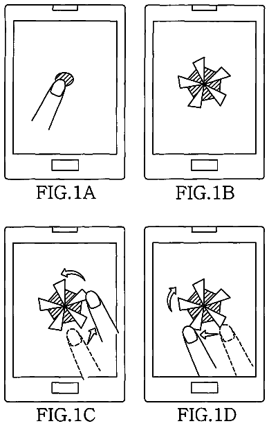
A method of disabling a locking screen of an electronic device is provided.
US 9,760,315 B2 · Assignee: NEC CORPORATION · Inventors: Taguchi; Masahiko
Sheet 1 of 28 from the published document. All sheets in the USPTO PDF
Disclosed is a dynamic device allocation apparatus capable of allocating dynamically and flexibly the I/O device, which inputs and outputs information, to the information processing carried out in the system. The dynamic device allocation apparatus includes, a device allocation information storing unit to store device allocation information associating an identifier of an input device apparatus, an identifier of an output device apparatus, and an identifier of the designated information processing apparatus; a registration unit to generate the device allocation information, which specifies contents of the information processing, and to register the generated device allocation information with the device allocation information storing unit; and an instruction unit to generate information processing instruction information which instructs the input device apparatus, the output device apparatus and the information processing apparatus to carry out the information processing according to the device allocation information.
In recent years, ‘thin client’, which is a solution enabling to do business without putting secret information in a local computing environment by utilizing an art to connect a remote computer, is get an attention in order to realize a high level security requirement. For example, software and a protocol such as VNC (Virtual Network Computing: registered trademark), RDP (Remote Desktop Protocol: registered trademark) or the like realize an operation in a remote desktop environment. In general, the thin client aggregates computing environments by using a virtualization art in order to reduce a facility investment cost and electric power consumption. For example, software with the hypervisor function enables a plurality of computing environments, such as a plurality of OSs (Operating System) or the like, to operate on one CPU. Meanwhile, as a need for doing business by using a mobile termi
1 of 28 drawing sheets so far from the published document, cropped to the drawing. Every sheet is in the USPTO PDF.
What the patent claimed, word for word. All of it is now free to use.
This application is based upon and claims the benefit of priority from Japanese Patent Application No. 2013-251591, filed on Dec. 5, 2013, the disclosure of which is incorporated herein in its entirety by reference.
The invention of the present application relates to a device allocation apparatus or the like which allocates an input device apparatus inputting target input information to which an information processing is carried out, and an output device apparatus outputting a result of the information processing which is carried out to the target input information.
In recent years, ‘thin client’, which is a solution enabling to do business without putting secret information in a local computing environment by utilizing an art to connect a remote computer, is get an attention in order to realize a high level security requirement. For example, software and a protocol such as VNC (Virtual Network Computing: registered trademark), RDP (Remote Desktop Protocol: registered trademark) or the like realize an operation in a remote desktop environment.
In general, the thin client aggregates computing environments by using a virtualization art in order to reduce a facility investment cost and electric power consumption. For example, software with the hypervisor function enables a plurality of computing environments, such as a plurality of OSs (Operating System) or the like, to operate on one CPU.
Meanwhile, as a need for doing business by using a mobile terminal becomes higher, to make the thin client environment and the mobile environment compatible each other is searched. For example, the application POCKETCLOUD (registered trademark) enables a tablet terminal or the like to use a remote desktop environment by using VNC and RDP on iOS (registered trademark) or Android (registered trademark).
In a case of making the thin client environment and the mobile environment compatible each other, information leakage by peek is a serious security problem. This is a problem on security vulnerability which has not been systematized yet. For this reason, for example, by adopting a head mount display (HMD) as a screen of a remote desktop, it is expected to make the peek impossible.
FIG. 26 shows a user's utilization form which combines the thin client environment and HMD. Since it is difficult generally to carry out an input operation smoothly in the case of HMD, it is supposed to use a terminal apparatus such as a touch pad or the like at the same time. Input information which a user inputs by use of a touch pad 1000 is sent to a data center 1002 through a wireless AP (Access Point) 1001 . The data center 1002 carries out information processing to the received input information, and outputs the processed information as output information, and the output information, which passes through the wireless AP 1001 , is displayed on HMD 1003 .
In this case, it is necessary to manage the touch pad 1000 which is an input device, and HMD 1003 which is an output device as nodes different each other in a communication network, and to connect these devices so that the security vulnerability may become small. Accordingly, an art to connect the I/O devices flexibly and safely becomes more important.
As an art related to such the art, a patent literature 1 (Japanese Unexamined Patent Application Publication No. Hei10-187584) discloses a system that an I/O device and a control mechanism for the I/O device are arranged separately and are connected each other through a communication network. The system mentioned above has a configuration that the I/O device and the control mechanism for the I/O device are not connected fixedly in one to one correspondence, but are connected at every necessary time.
As a related art, a patent literature 2 (Japanese Unexamined Patent Application Publication No. 2004-192077) discloses a system that, when providing a service on the basis of a service scenario, an apparatus or the like which has a function indicated in the scenario is searched locally. By carrying out association among used apparatuses to each found apparatus, the system applies the same service to various locations and facilities.
As a related art, a patent literature 3 (Japanese Unexamined Patent Application Publication No. 2008-065828) discloses an art that, in a system to carry out a performance analysis on a supply chain facility, information and data which are transferred through a communication network are encrypted.
In order to construct flexibly a system which includes a combination of the thin client environment and the mobile environment, it is requested that I/O devices, which input or output information related to information processing carried out in the system, are allocated flexibly to each information processing with no restriction due to a physical configuration of the system.
The arts disclosed in the patent literature 1 and 2 assume that all apparatuses such as the I/O device or the like are connected with the communication network, and send and receive information through the communication network. However, with respect to the information processing carried out in the system, there is a case that, for example, information flows from the input device to the output device not through the communication network, and the arts disclosed in the patent literature 1 and 2 do not assume the case. Moreover, the art disclosed in the patent literature 3 is not the art which allocates the I/O device flexibly to the information processing carried out in the system. Accordingly, it is difficult for the arts disclosed in the patent literature 1 to 3 to solve the problem mentioned above sufficiently.
A main object of the invention according to the present application is to provide a dynamic device allocation apparatus or the like which can solve the problem mentioned above.
A dynamic device allocation apparatus according to an exemplary aspect of the present invention includes: a device allocation information storing unit to store device allocation information associating an input device identifier which can identify an input device apparatus inputting information into a designated information processing apparatus, an output device identifier which can identify an output device apparatus inputting information which is outputted from the designated information processing apparatus, and an information processing apparatus identifier capable of identifying the designated information processing apparatus which inputs a result of information processing carried out to information, which is inputted from the input device apparatus which is designated, into the output device apparatus which is designated; a registration unit to generate the device allocation information, which specifies contents of the information processing, when the designated information processing apparatus carries out the information processing, and to register the generated device allocation information with the device allocation information storing unit; and an instruction unit to generate information processing instruction information which instructs the input device apparatus, the output device apparatus and the information processing apparatus to carry out the information processing according to the device allocation information which the device allocation information storing unit stores.
A dynamic device allocation method according to an exemplary aspect of the present invention includes: by a first information processing apparatus, storing device allocation information in a device allocation information storing unit, which is associating an input device identifier which can identify an input device apparatus inputting information into a designated second information processing apparatus, an output device identifier which can identify an output device apparatus inputting information which is outputted from the designated second information processing apparatus, and an information processing apparatus identifier capable of identifying the designated second information processing apparatus which inputs a result of information processing carried out to information, which is inputted from the input device apparatus which is designated, into the output device apparatus which is designated; by the first information processing apparatus, generating the device allocation information, which specifies contents of the information processing, when the designated second information processing apparatus carries out the information processing, and registering the generated device allocation information with the device allocation information storing unit; and by the first information processing apparatus, generating information processing instruction information which instructs the input device apparatus, the output device apparatus and the second information processing apparatus to carry out the information processing according to the device allocation information which the device allocation information storing unit stores.
A non-transitory computer-readable medium according to an exemplary aspect of the present invention stores a computer program causing a computer to realize: a device allocation information storing function that stores device allocation information in a device allocation information storing unit, which is associating an input device identifier which can identify an input device apparatus inputting information into a designated information processing apparatus, an output device identifier which can identify an output device apparatus inputting information which is outputted from the designated information processing apparatus, and an information processing apparatus identifier capable of identifying the designated information processing apparatus which inputs a result of information processing carried out to information, which is inputted from the input device apparatus which is designated, into the output device apparatus which is designated; a registration function that generates the device allocation information, which specifies contents of the information processing, when the designated information processing apparatus carries out the information processing, and to register the generated device allocation information with the device allocation information storing unit; and an instruction function that generates information processing instruction information which instructs the input device apparatus, the output device apparatus and the information processing apparatus to carry out the information processing according to the device allocation information which the device allocation information storing unit stores.
Exemplary features and advantages of the present invention will become apparent from the following detailed description when taken with the accompanying drawings in which:
FIG. 1 is a block diagram showing an outlined configuration of a dynamic device allocation system according to a first exemplary embodiment of the invention of the present application;
FIG. 2 is a block diagram showing a detailed configuration of the dynamic device allocation system according to the first exemplary embodiment of the invention of the present application;
FIG. 3A is a flowchart ( 1 / 2 ) showing a device registration operation of the dynamic device allocation system according to the first exemplary embodiment of the invention of the present application;
FIG. 3B is a flowchart ( 2 / 2 ) showing the device registration operation of the dynamic device allocation system according to the first exemplary embodiment of the invention of the present application;
FIG. 4 is a flowchart showing a device usage operation of the dynamic device allocation system according to the first exemplary embodiment of the invention of the present application;
FIG. 5 is a block diagram showing a physical configuration of a first modification of the dynamic device allocation system according to the first exemplary embodiment of the invention of the present application;
FIG. 6 is a block diagram showing an outline of a logical configuration of the first modification of the dynamic device allocation system according to the first exemplary embodiment of the invention of the present application;
FIG. 7 is a block diagram showing details of the logical configuration of the first modification of the dynamic device allocation system according to the first exemplary embodiment of the invention of the present application;
FIG. 8 is a block diagram showing a physical configuration of a second modification of the dynamic device allocation system according to the first exemplary embodiment of the invention of the present application;
FIG. 9 is a block diagram showing an outline of a logical configuration of the second modification of the dynamic device allocation system according to the first exemplary embodiment of the invention of the present application;
FIG. 10 is a block diagram showing details of the logical configuration of the second modification of the dynamic device allocation system according to the first exemplary embodiment of the invention of the present application;
FIG. 11 is a block diagram showing a physical configuration of a third modification of the dynamic device allocation system according to the first exemplary embodiment of the invention of the present application;
FIG. 12 is a block diagram showing an outline of a logical configuration of the third modification of the dynamic device allocation system according to the first exemplary embodiment of the invention of the present application;
FIG. 13 is a block diagram showing details of the logical configuration of the third modification of the dynamic device allocation system according to the first exemplary embodiment of the invention of the present application;
FIG. 14 is a block diagram showing a physical configuration of a fourth modification of the dynamic device allocation system according to the first exemplary embodiment of the invention of the present application;
FIG. 15 is a block diagram showing an outline of a logical configuration of the fourth modification of the dynamic device allocation system according to the first exemplary embodiment of the invention of the present application;
FIG. 16 is a block diagram showing a physical configuration of a fifth modification of the dynamic device allocation system according to the first exemplary embodiment of the invention of the present application;
FIG. 17 is a block diagram showing details of a logical configuration of the fifth modification of the dynamic device allocation system according to the first exemplary embodiment of the invention of the present application;
FIG. 18 is a block diagram showing a physical configuration of a sixth modification of the dynamic device allocation system according to the first exemplary embodiment of the invention of the present application;
FIG. 19 is a block diagram showing an outline of a logical configuration of the sixth modification of the dynamic device allocation system according to the first exemplary embodiment of the invention of the present application;
FIG. 20 is a block diagram showing details of the logical configuration of the sixth modification of the dynamic device allocation system according to the first exemplary embodiment of the invention of the present application;
FIG. 21 is a block diagram showing a physical configuration of a seventh modification of the dynamic device allocation system according to the first exemplary embodiment of the invention of the present application;
FIG. 22 is a block diagram showing an outline of a logical configuration of the seventh modification of the dynamic device allocation system according to the first exemplary embodiment of the invention of the present application;
FIG. 23 is a block diagram showing details of the logical configuration of the seventh modification of the dynamic device allocation system according to the first exemplary embodiment of the invention of the present application;
FIG. 24 is a block diagram showing a configuration of a dynamic device allocation apparatus according to a second exemplary embodiment of the invention of the present application;
FIG. 25 is a block diagram showing a configuration of an information processing apparatus which can carry out the dynamic device allocation apparatus according to each the exemplary embodiment and the modification of each the exemplary embodiment of the invention of the present application;
FIG. 26 is a diagram exemplifying an usage form combining HMD with the thin client environment which is a background of the invention of the present application; and
FIG. 27 is a diagram expressing the first exemplary embodiment of the invention of the present application by use of the MVC model.
Hereinafter, an exemplary embodiment of the present invention will be described in detail with reference to drawings. First Exemplary Embodiment
FIG. 1 is a conceptual block diagram showing an outlined configuration of a dynamic device allocation system 100 of a first exemplary embodiment. FIG. 2 is a conceptual block diagram showing a detailed configuration of the dynamic device allocation system 100 of the first exemplary embodiment.
The dynamic device allocation system 100 includes a dynamic device allocation apparatus 1 , an input hub apparatus 2 , a remote resource 3 , an output hub apparatus 4 , an input device 52 , an output device 54 and a networking client 7 . Here, while number of each component, which is described in the figure, is just one for convenience of explanation, there is a case that the dynamic device allocation system 100 includes a plurality of components of the same type.
When information processing is carried out in the dynamic device allocation system 100 , the dynamic device allocation apparatus 1 associates dynamically an input device which inputs information into the information processing, and an output device which outputs a result of the information processing. The dynamic device allocation apparatus 1 includes a registration unit 10 , an instruction unit 11 and a device allocation information storing unit 12 . There is a case that each of the registration unit 10 and the instruction unit 11 is an electronic circuit, or is a computer program and a processor which works according to the computer program. The device allocation information storing unit 12 is an electronic circuit or an electronic device such as an electronic memory, a magnetic disk or the like to which access control is carried out by a computer program and a processor working according to the computer program.
When a specific information processing is carried out in the dynamic device allocation system 100 , the registration unit 10 receives base information, which is used when generating device allocation information on the information processing, from the input hub apparatus 2 . The device allocation information is information which associates an identifier which can identify the remote resource 3 or the networking client 7 carrying out the information processing, an identifier which can identify the input device inputting information into the information processing, and an identifier which can identify the output device inputting information outputted from the information processing. After generating the device allocation information on the basis of the received base information, the registration unit 10 registers the generated device allocation information with the device allocation information storing unit 12 , and sends a notification, which indicates that the device allocation information is registered, to the instruction unit 11 .
The device allocation information storing unit 12 stores the inputted device allocation information as one record. After receiving the notification which indicates that the device allocation information is registered, the instruction unit 11 reads the device allocation information from the device allocation information storing unit 12 . The instruction unit 11 generates information processing instruction information to instruct the remote resource 3 or the networking client 7 , the input device and the output device, which are identified by each identifier included in the device allocation information, to carry out the information processing. The instruction unit 11 sends the information processing instruction information to the input hub apparatus 2 , the output hub apparatus 4 , and the remote resource 3 or the networking client 7 .
The input hub apparatus 2 controls inputting information which is provided by each input device such as the input device 52 or the like. The input hub apparatus 2 includes an input hub agent 21 , an output hub list 22 , an input unit 23 and a beacon receiving unit 24 . The input hub agent 21 includes a usage reservation requesting part 210 , a mapping requesting part 211 and a usage deciding part 212 . The input unit 23 includes an input receiving part 230 and an input device list 232 .
The beacon receiving unit 24 receives list information on output devices, which the information processing can use, from the output hub apparatus 4 before the information processing is carried out in the dynamic device allocation system 100 . After selecting the output device 54 , which is connected with the output hub apparatus 4 , from the list information on the available output device, the usage reservation requesting part 210 sets the selected output device 54 to “reservation state” and registers the setting with the output hub list 22 . At this point of time, the usage reservation requesting part 210 registers the remote resource 3 or the networking client 7 in association with the output device 54 . The usage reservation requesting part 210 notifies the output hub apparatus 4 of having reserved the output device 54 .
The mapping requesting part 211 sends the base information, which is used when generating the above-mentioned device allocation information on the information processing, to the dynamic device allocation apparatus 1 . After receiving the information processing instruction information from the dynamic device allocation apparatus 1 , the usage deciding part 212 updates a state of the output device 54 , which is registered with the output hub list 22 , from ‘reservation state’ to ‘in use’.
After the information processing is started in the dynamic device allocation system 100 , the input receiving part 230 receives input information from the input device 52 . The input receiving part 230 sends the input information, which is received from the input device 52 , to the remote resource 3 or the networking client 7 on the basis of the output hub list 22 .
The output hub apparatus 4 controls outputting information to each output device such as the output device 54 . The output hub apparatus 4 includes an output hub agent 41 , an input hub list 42 , an output unit 43 and a beacon sending unit 44 . The output hub agent 41 includes a usage reservation receiving part 410 , a beacon stopping part 411 and a usage deciding part 412 . The output unit 43 includes an output receiving part 430 and an output device list 432 .
The beacon sending unit 44 sends list information on an output device, which is in an unused state, to the input hub apparatus 2 before the information processing is carried out in the dynamic device allocation system 100 . The usage reservation receiving part 410 is notified by the input hub apparatus 2 of having reserved the output device 54 . Afterward, the usage reservation receiving part 410 sets the input device 52 , which inputs the input information into the information processing and which is connected with the input hub apparatus 2 , to ‘reservation state’, and registers the setting with the input hub list 42 . At this point of time, the usage reservation requesting part 210 registers the output device 54 in association with the input device 52 . The usage reservation receiving part 410 stops an operation of the beacon sending unit 44 by use of the beacon stopping part 411 , and hereinafter does not notify the input hub apparatus 2 of the list information on the output device which is in the unused state. After receiving the information processing instruction information from the dynamic device allocation apparatus 1 , the usage deciding part 212 updates a state of the input device 52 , which is registered with the input hub list 42 , from ‘reservation state’ to ‘in use’.
After the information processing is started in the dynamic device allocation system 100 , the output receiving part 430 receives information, to which information processing is carried out, from the remote resource 3 or the networking client 7 . The output receiving part 430 sends the information, to which the information processing is carried out, to the output device 54 on the basis of the input hub list 42 .
The remote resource 3 is a resource which includes an information processing apparatus or the like and carries out various information processing. For example, the remote resource 3 is corresponding to a server apparatus in the thin client system. The remote resource 3 includes a remote resource agent 31 , a virtual controller 32 , a virtual view 34 and an existing system 53 . The remote resource agent 31 includes a registration receiving part 310 . The virtual controller 32 includes an input data converting part 320 . The virtual view 34 includes output data 340 .
Before the information processing is carried out in the dynamic device allocation system 100 , the registration receiving part 310 acquires device specification information on the input device 52 and device specification information on the output device 54 from the input device list 232 and the output device list 432 respectively. The input device 52 and the output device 54 are designated by the information processing instruction information which is received from the dynamic device allocation apparatus 1 . The registration receiving part 310 inputs the acquired device specification information on the input device 52 , and the acquired device specification information on the output device 54 to the input data converting part 320 and the output data converting part 340 respectively.
After the information processing is started in the dynamic device allocation system 100 , the input data converting part 320 converts the input information, which is received from the input hub apparatus 2 , into a form, which the existing system 53 can process, on the basis of the device specification information. The input data converting part 320 inputs the converted input information into the existing system 53 . The output data converting unit 340 converts information, which is processed by the existing system 53 , into a form, which the output device 54 can process, on the basis of the device specification information, and afterward inputs the converted information into the output hub apparatus 4 .
The networking client 7 is a resource which carries out an information processing. For example, the networking client 7 is corresponding to CPU (Central Processing Unit) of a thin client terminal apparatus in the thin client system. After the information processing is started in the dynamic device allocation system 100 , the networking client 7 processes the input information, which is received from the input hub apparatus 2 , according to the information processing instruction information which is received from the dynamic device allocation apparatus 1 . The networking client 7 inputs a result of the information processing into the output hub device 4 .
Next, with reference to flow charts shown in FIG. 3A to 3B , a device registration operation (process) carried out by the dynamic device allocation system 100 of the exemplary embodiment will be described in detail.
When the remote resource 3 or the networking client 7 carries out information processing, the beacon sending unit 44 sends an identifier list identifying an output device, which is in an available state, out of the output devices such as the output device 54 to the beacon receiving unit 24 (Step 101 ). The usage reservation requesting part 210 selects at least any one of the output devices from the identifier list which the beacon receiving unit 24 receives, and reserves to use the selected output device. Then, the usage reservation requesting part 210 registers an identifier, which identifies the output device, with the output hub list 22 as ‘reservation state’, and inputs the registered identifier into the usage reservation receiving part 410 (Step S 102 ).
On the basis of the information which is inputted from the usage reservation requesting part 210 , the usage reservation receiving part 410 registers an identifier, which identifies the input device inputting information into the information processing, with the input hub list 42 as ‘reservation state’ (Step S 103 ). On the basis of the information which is inputted from the usage reservation requesting part 210 , the usage reservation receiving part 410 instructs the beacon sending unit 44 to stop sending the identifier list, which identifies the output device which is in the available state, by use of the beacon stopping part 411 (Step S 104 ).
The mapping requesting part 211 associates the identifier which identifies the remote resource 3 or the networking client 7 carrying out the information processing, the identifier which identifies the reserved input device, and the identifier which identifies the reserved output device, and inputs the association into the registration unit 10 (Step S 105 ). The registration unit 10 generates the device allocation information on the basis of the information which is inputted from the mapping requesting part 211 , and registers the generated device allocation information with the device allocation information storing unit 12 , and notifies the instruction unit 11 of having registered the device allocation information (Step S 106 ).
The instruction unit 11 reads the device allocation information from the device allocation information storing unit 12 , and generates the information processing instruction information, which instructs to carry out the information processing, on the basis of the device allocation information. The instruction unit 11 inputs the generated information processing instruction information into the usage deciding part 212 , the usage deciding part 412 , and the registration receiving part 310 or the networking client 7 (Step S 107 ). The usage deciding part 212 updates the state, which is an attribute of the identifier identifying the output device designated by the received information processing instruction information and which is registered with the output hub list 22 , from ‘reservation state’ to ‘in use’ (Step S 108 ).
The usage deciding part 412 updates the state, which is an attribute of the identifier identifying the input device designated by the received information processing instruction information and which is registered with the input hub list 42 , from ‘reservation state’ to ‘in use’ (Step S 109 ). The registration receiving part 210 acquires specification information on the input device, which the information processing instruction information designates, from the input device list 232 , and acquires specification information on the output device, which the information processing instruction information designates, from the output device list 432 (Step S 110 ). The registration receiving part 210 inputs the acquired specification information on the input device into the input data converting part 320 , and inputs the acquired specification information on the output device into the output data converting part 340 (Step S 111 ), and a whole of process is completed.
Next, with reference to a flowchart shown in FIG. 4 , a device usage operation (process) of the dynamic device allocation system 100 of the exemplary embodiment will be described in detail. Here, the flowchart shows an operation which is carried out when the input device 52 and the output device 54 are allocated as the input device and the output device related to the information processing respectively.
The input receiving part 230 acquires the input information from the input device 52 which is in the state of ‘in use’ (Step S 201 ). In the case that an execution subject, which is designated by the information processing instruction information and which carries out the information processing, is not the remote resource 3 (that is, execution subject is the networking client 7 ) (No in Step S 202 ), the networking client 7 acquires the input information from the input receiving part 230 . The networking client 7 inputs information processing output information, which is a result of the information processing, into the output receiving part 430 as the output information (Step S 203 ), and the process advances towards Step S 207 .
In the case that the execution subject, which is designated by the information processing instruction information and which carries out the information processing, is the remote resource 3 (Yes in Step S 202 ), the input data converting part 320 acquires the input information from the input receiving part 230 . The input data converting part 320 converts the input information to generate information processing input information, and inputs the generated information processing input information into the existing system 53 (Step S 204 ). The existing system 53 generates the information processing output information, which is a result of the information processing carried out to the information processing input information, and inputs the generated information processing output information into the output data converting part 340 (Step S 205 ). The output data converting part 340 converts the information processing output information to generate the output information, and inputs the output information to the output receiving part 430 (Step S 206 ). The output receiving part 430 inputs the output information into the output device 54 , which is in the state of ‘in use’ (Step S 207 ), and a whole of process is completed.
The dynamic device allocation system 100 according to the exemplary embodiment can allocate dynamically and flexibly the I/O device, which inputs and outputs the information related to the information processing, to the information processing carried out in the system. The reason is that the dynamic device allocation apparatus 1 , the execution subject, the input device and the output device operate as follows. That is, on the basis of the device allocation information which associates the identifier of the execution subject carrying out the information process, the identifier of the input device, and the identifier of the output device, the dynamic device allocation apparatus 1 instructs the execution subject, the input device and the output device to carry out the information processing. Then, the execution subject, the input device and the output device carry out the information processing according to contents of the instruction issued by the dynamic device allocation apparatus 1 .
FIG. 27 is a diagram expressing the exemplary embodiment by use of the MVC (Model-View-Controller) model which is known as the design model related to software.
The MVC model is a design model which expresses a system by use of a combination of three components, that is, ‘model’ which is a core of information processing, ‘view’ which processes an output, and ‘controller’ which controls ‘model’ and ‘view’ according to contents of a received input. According to the exemplary embodiment, the remote resource 3 is corresponding to ‘model’, and the output hub apparatus 4 is corresponding to ‘view’, and the input hub apparatus 2 is corresponding to ‘controller’. The dynamic device allocation apparatus 1 according to the exemplary embodiment associates ‘model’, ‘view’ and ‘controller’ per the information processing, and afterward instructs ‘model’, ‘view’ and ‘controller’ to carry out the information processing. Accordingly, the dynamic device allocation system 100 can construct dynamically and flexibly a flow, which is related to the information processing, per the information processing. The flow related to the information processing is a flow in which information inputted by any one of the input devices is processed by any one of the information processing apparatuses, and a result of the information processing is outputted to any one of the output devices.
For example, in the case of the general thin client environment, a server apparatus is corresponding to ‘model’, and a thin client terminal apparatus is corresponding to ‘controller’ and ‘view’. In detail, an input control unit which controls an information input from a keyboard and a mouse of the thin client terminal apparatus is corresponding to ‘controller’, and an output control unit which controls an information output provided to a display is corresponding to ‘view’. Here, CPU (not shown in the MVC model shown in FIG. 27 ) which operates the thin client terminal apparatus is corresponding to the networking client 7 shown in FIG. 1 .
A flow related to the general information processing in the thin client environment is ‘controller’.fwdarw.‘model’.fwdarw.‘view’. However, for example, in the case of an information processing to make a display released from the power saving mode by an user's operating a mouse, an amount of communication traffic can be reduced in the case of carrying out a process according to a flow of ‘controller’.fwdarw.‘view’ in comparison with an amount of communication traffic in the case of carrying out a process according to the flow of ‘controller’.fwdarw.‘model’.fwdarw.‘view’. As a result, it is expected to improve responsiveness in an environment that a communication network has a narrow bandwidth or the like. The dynamic device allocation system 100 according to the exemplary embodiment can construct dynamically and flexibly the flow of ‘controller’.fwdarw.‘model’.fwdarw.‘view’ or ‘controller’.fwdarw.‘view’.
Without depending on the physical configuration related to the system, the dynamic device allocation system 100 associates the input device, the information processing apparatus and the output device. For example, even in the case that the input device and the output device do not exist in one apparatus like the thin client terminal apparatus, and that each of the input device and the output device exists independently as one apparatus, the dynamic device allocation system 100 can carry out the association mentioned above. Accordingly, in order to improve fault tolerance, and convenience related to a system change, the dynamic device allocation system 100 can construct flexibly a system which distributes the information processing apparatus and the I/O device.
According to the exemplary embodiment, the remote resource 3 acquires the device specification information on the input device and the device specification information on the output device from the input hub apparatus 2 and the output hub apparatus 4 respectively when carrying out the information processing, and converts a data form on the basis of the device specification information. Accordingly, the dynamic device allocation system 100 can cope with an I/O device, which includes a special interface, flexibly.
The description continues in the full USPTO document.
About 6,171 words. The USPTO PDF has it with every drawing.
Fees are due 3.5, 7.5 and 11.5 years after grant. This patent expired on September 12, 2025, so the fee marked "not paid" was the one that went unpaid.
DYNAMIC DEVICE ALLOCATION APPARATUS, DYNAMIC DEVICE ALLOCATION SYSTEM, DYNAMIC DEVICE ALLOCATION METHOD AND STORAGE MEDIUM STORING DYNAMIC DEVICE ALLOCATION PROGRAM
Filed Oct 2014 · published Jun 2015Dynamic device allocation apparatus, dynamic device allocation system, dynamic device allocation method and storage medium storing dynamic device allocation program
Filed Oct 2014 · granted Sep 2017Earlier publications, parents and continuations. None of them can still be enforced, or this patent would not be listed.
Prior art cited by the examiner or applicant. Useful when you check your own idea for novelty.
Everything on this page comes from the documents linked above.