 Lapsed, fee not paid4 drawings
Industrial Equipment · US 9,758,998 B2
Motor vehicle door with hinge reinforcement
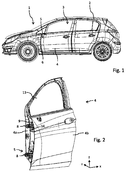
A motor vehicle door is configured to hingedly mount to the body of a motor vehicle.
US 9,759,004 B2 · Assignee: NABTESCO CORPORATION · Inventors: Uno; Hiroki et al.
Sheet 1 of 15 from the published document. All sheets in the USPTO PDF
An opening and closing apparatus with a lock that is provided is capable of safely and promptly closing a sliding door, and also easily performing unlocking with a simple configuration. In an opening and closing apparatus with a lock for opening and closing sliding doors that are provided with elastic members at their door leading ends, output of an electric motor is transmitted to a rack-and-pinion mechanism or a lock mechanism. A control unit controls the electric motor such that a closing operation is performed, the closing operation operates the rack-and-pinion mechanism so as to move the sliding doors to a fully closed position and then displacing a link mechanism in a lock mechanism from an unlocking position to a locking position. Furthermore, the control unit controls the electric motor so as to reduce the output of the electric motor at a predetermined intermediate time point during the closing operation.
There are known to be opening and closing apparatuses with a lock that move a sliding door provided in a railway vehicle or the like to open and close, and lock the sliding door at a fully closed position (e.g., see Patent Document 1). The opening and closing apparatus with a lock recited in Patent Document 1 has a planetary gear mechanism to which a driving force of an actuator is input, and a rack-and-pinion mechanism configured to receive output from the planetary gear mechanism. When sliding doors are opened and closed, a driving force of the actuator is output to the rack-and-pinion mechanism via the planetary gear mechanism, and rotates a pinion. With the rotation of the pinion, a rack that meshes with the pinion moves linearly. Thus, sliding doors, which are coupled to the rack, move linearly. When the sliding doors are closed up to the fully closed position, the sliding doors are
1 of 15 drawing sheets so far from the published document, cropped to the drawing. Every sheet is in the USPTO PDF.
What the patent claimed, word for word. All of it is now free to use.
The present invention relates to an opening and closing apparatus with a lock for performing opening and closing operations and a locking operation for a vehicle sliding door, using one actuator.
There are known to be opening and closing apparatuses with a lock that move a sliding door provided in a railway vehicle or the like to open and close, and lock the sliding door at a fully closed position (e.g., see Patent Document 1).
The opening and closing apparatus with a lock recited in Patent Document 1 has a planetary gear mechanism to which a driving force of an actuator is input, and a rack-and-pinion mechanism configured to receive output from the planetary gear mechanism. When sliding doors are opened and closed, a driving force of the actuator is output to the rack-and-pinion mechanism via the planetary gear mechanism, and rotates a pinion. With the rotation of the pinion, a rack that meshes with the pinion moves linearly. Thus, sliding doors, which are coupled to the rack, move linearly. When the sliding doors are closed up to the fully closed position, the sliding doors are locked by a lock mechanism.
The lock mechanism has an engaging member that can rotate around a shaft. The engaging member has a first engaging portion for engaging with a lock pin fixed to the sliding door. When the sliding doors approach the fully closed position while they are being closed, the lock pin comes into contact with the first engaging portion and rotates the engaging member. At the fully closed position, the first engaging portion surrounds the lock pin. The rotation of the engaging member is restricted in this state, and the movement of the lock pin as well as the movement of the sliding doors are restricted.
More specifically, when the sliding doors reach the fully closed position, the pinion that meshes with the rack cannot rotate in the direction of closing the sliding doors any more. When a sun gear in the planetary gear mechanism rotates in the direction of closing the sliding doors in this state, the pinion revolves within an internal gear, and a carrier rotates. With the rotation of the carrier, a lock slider disposed in the vicinity of the carrier is displaced. With this displacement, a link mechanism coupled to the lock slider undergoes deformation from a bent state to a linear state. Then, an end of the link mechanism goes into a second engaging portion having a recessed shape that is formed on the engaging member, and restricts the rotation of the engaging member as mentioned above. CITATION LIST Patent Document
Patent Document 1: JP 2008-121244A DISCLOSURE OF THE INVENTION Problem to be Solved by the Invention
Usually, an elastic member such as rubber is attached to a door leading end of a sliding door for a railroad vehicle. For example, in the case of two-panel sliding doors, when the pair of sliding doors are at a fully closed position, lips of the elastic members of the respective door leading ends come into contact with each other.
With sliding doors for a railroad vehicle, when the sliding doors are closed, there are cases where the sliding doors are closed up to the fully closed position while a passenger's luggage is stuck therebetween, and the sliding doors are then locked. In such cases, the luggage is in a state of being stuck between the elastic members. In this state, a reaction force from the luggage is exerted on the sliding doors, and this reaction force is transmitted from the sliding doors to the engaging member via the lock pin. For this reason, the engaging member presses an end of a link mechanism engaging with the engaging member, around the rotation centers of the engaging member. That is to say, the engaging member presses the end of the link mechanism in a direction other than the direction in which the link mechanism is disengaged from the engaging member. If an attempt is made to disengage the link mechanism from the second engaging portion of the engaging member in this state, the engaging member pries the end of the link mechanism, and it is difficult to smoothly cancel the rotation restriction on the engaging member by the link mechanism, that is, to smoothly perform unlocking.
In particular, if the output of the actuator for closing the sliding doors is large, the sliding doors are forcibly closed and the lock mechanism is locked even when a piece of luggage or the like is stuck between the door leading ends, and the reaction force from the stuck luggage also tends to be larger. As a result, as the force of closing the sliding doors is larger, it is more difficult to pull out the luggage stuck between the door leading ends.
In that case, it is conceivable that an operator such as an attendant performs unlocking by operating an unlock mechanism, manually operating the link mechanism to disengage the link mechanism from the engaging member, and enabling the engaging member to rotate, and then pulls the luggage out of the sliding doors. However, a large force is required to manually operate the link mechanism that engages with the engaging member with a large prying force, and accordingly, a force amplifying mechanism for amplifying the operator's force is needed. However, if the force amplifying mechanism is added, the scale of the opening and closing apparatus with a lock becomes larger.
On the other hand, in order to prevent the sliding doors from being forcibly locked in the state where a piece of luggage is stuck, it is conceivable to make the output of the actuator small. However, in the case of this configuration, if, for example, a passenger leans against the sliding doors while the operation of closing the sliding doors is being performed in a crowded train, a large resistance force is exerted on the sliding doors, which leads to misrecognition that something is stuck between the doors, and the sliding door cannot be closed promptly. For this reason, it takes time to close the sliding door, which is not preferable in terms of maintenance of scheduled service.
In light of the foregoing situation, an object of the present invention is to provide an opening and closing apparatus with a lock capable of safely and promptly closing a sliding door, and also easily performing unlocking with a simple configuration. Means for Solving the Problem
An opening and closing apparatus with a lock according to a first aspect of the present invention for achieving the above-stated object is an opening and closing apparatus with a lock for opening and closing a sliding door that is installed at an entrance of a vehicle and is provided with an elastic member at its door leading end, the opening and closing apparatus with a lock including; an actuator; a moving mechanism for moving the sliding door in a predetermined opening direction and closing direction, using output of the actuator; a lock mechanism that operates using output of the actuator and is capable of restricting movement of the sliding door in the opening direction when the sliding door is at a fully closed position; and a control unit for controlling the actuator, wherein the lock mechanism includes an engaging member capable of engaging with a lock member capable of integrally moving with the sliding door, so as to restrict movement of the lock member in the opening direction, and a restricting member capable of being displaced between a locking position for restricting displacement of the engaging member when engaging with the lock member and an unlocking position for allowing displacement of the engaging member, with an operation of the actuator, and the control unit controls the actuator such that a closing operation is performed, the closing operation serving as an operation of operating the moving mechanism so as to move the sliding door along the closing direction to the fully closed position and then displacing the restricting member from the unlocking position to the locking position, and, at a predetermined intermediate time point during the closing operation, controls the actuator so as to reduce the output of the actuator from a predetermined first driving force to a second driving force.
According to this aspect of the invention, the first driving force serving as the output of the actuator is increased until the predetermined intermediate time point during the closing operation. For this reason, a decrease in the closing speed of the sliding door can be suppressed when the sliding door is being displaced toward the fully closed position with the output of the actuator, and it is therefore possible to promptly close the sliding door. For example, even in the case where a large movement resistance is exerted on the sliding door as a result of a passenger leaning against the sliding door while the sliding door is being closed in a crowded train, it is possible to keep promptly closing the sliding door due to the force that closes the sliding door being sufficiently large. In particular, maintenance of scheduled service is strongly demanded for railroad vehicles, and realization of a prompt full-closing operation for the sliding door will significantly contribute to an improvement in the maintenance of scheduled service. Further, the output of the actuator when the restricting member is displaced to the locking position and engages with the engaging member can be made small by reducing the output of the actuator from the first driving force to the second driving force at the predetermined intermediate time point during the closing operation. Therefore, for example, in the case where a piece of luggage is pressing the sliding door toward the opening direction via the elastic member at the fully closed position in a state where the luggage is stuck at the door leading end, if the reaction force from the luggage is large, the sliding door is slightly displaced in the opening direction after reaching the fully closed position once. For this reason, the sliding door is not locked. Also in the case where a piece of luggage is stuck at the door leading end and the sliding door does not move at the closed position, the sliding door is not locked. Accordingly, the sliding door can be prevented from being forcibly locked with a large force. Even if the sliding door is locked in a state where a thin piece of luggage or the like is stuck at the door leading end, the reaction force from the luggage in this case is small. For this reason, the engaging force exerted between the lock member and the engaging member is small, and consequently, the engaging force exerted between the engaging member and the restricting member is also small. Therefore, for example, in the case of manually displacing the restricting member from the locking position to the unlocking position to unlock the sliding door and pull out the luggage stuck at the door leading end, only a small force is required for the manual operation. Accordingly, a force enhancing mechanism such as a pulley mechanism for amplifying manpower for performing manual unlocking is unnecessary. Therefore, it is not necessary to add a new mechanism for manual unlocking or the like to the opening and closing apparatus with a lock, and the configuration of the opening and closing apparatus with a lock can be simplified.
Accordingly, according to the present invention, it is possible to provide an opening and closing apparatus with a lock capable of safely and promptly closing a sliding door, and also easily performing unlocking with a simple configuration.
An opening and closing apparatus with a lock according to a second aspect of the present invention is the opening and closing apparatus with a lock of the first aspect of the present invention, wherein a pair of sliding doors are provided such that door leading ends thereof face each other, and the predetermined intermediate time point during the closing operation is a time point when the sliding doors reach a position where the elastic members of the sliding doors come into contact with each other.
According to this aspect of the invention, the output of the actuator is reduced at the time point when the elastic members of the pair of sliding doors come into contact with each other. Accordingly, when the sliding doors are moving toward each other, the sliding doors can be promptly displaced in the closing direction with the large first driving force from the actuator. Further, for example, in the case where a piece of luggage is stuck at the door leading end and a reaction force from this luggage is large, it is possible to prevent the locking operation from being performed, due to the sliding doors moving in the opening direction against the second driving force of the actuator at an early stage after the luggage is stuck between the sliding doors. Accordingly, the luggage can be pulled out of the sliding doors at an earlier time point, and the damage to the luggage can be made small.
An opening and closing apparatus with a lock according to a third aspect of the present invention is the opening and closing apparatus with a lock of the first or second aspect of the present invention, wherein at a time point before the predetermined intermediate time point during the closing operation, if the actuator is forcibly stopped, the control unit controls the actuator so as to increase the first driving force.
According to this aspect of the invention, for example, if a passenger leans against the sliding door and a large movement resistance is exerted on the sliding door when the sliding door is closed in a crowded train, the output of the actuator is increased. Thus, a decrease in the closing speed of the sliding door can be suppressed, and the prompt closing operation for the sliding door can be reliably performed.
An opening and closing apparatus with a lock according to a fourth aspect of the present invention is the opening and closing apparatus with a lock of the third aspect of the present invention, wherein if a state where the actuator is forcibly stopped continues for a predetermined time, the control unit controls the actuator so as to reduce the output of the actuator, set the output of the actuator to zero, or reverse a direction of the output of the actuator.
According to this aspect of the invention, for example, when a passenger runs into a train and is stuck at the sliding door when the sliding door is closed in a crowded train, the actuator is forcibly stopped. If such a state continues for a predetermined time, the force that moves the sliding door to the closing direction is reduced or set to zero, or the sliding door is opened, thereby enabling the passenger to easily get out of the sliding door. Thus, a person, a piece of luggage, or the like that is stuck at the sliding door can be easily pulled out of the sliding door at a stage before the predetermined intermediate time point.
An opening and closing apparatus with a lock according to a fifth aspect of the present invention is the opening and closing apparatus with a lock of any of the first to fourth aspects of the present invention, wherein at a time point at or after the predetermined intermediate time point during the closing operation, the control unit controls the actuator such that the second driving force is constant.
According to this aspect of the invention, at or after the predetermined intermediate time point during the closing operation, even if a thick piece of luggage or the like is stuck at the door leading end, the output of the actuator is not increased, and the operation of forcibly closing the sliding door is not performed. For this reason, in the case where a thick piece of luggage or the like is stuck at the door leading end, the sliding door can be prevented from being forcibly locked. Accordingly, only a small force is exerted between the engaging member in the lock mechanism and the restricting member. Therefore, even in the case where unlocking needs to be performed by manually operating the restricting member, the restricting member can be easily disengaged from the engaging member with a small force to perform unlocking.
An opening and closing apparatus with a lock according to a sixth aspect of the present invention is the opening and closing apparatus with a lock of any of the first to fifth aspects of the present invention, wherein at a time point at or after the predetermined intermediate time point during the closing operation, when the actuator is forcibly stopped, the control unit controls the actuator so as to reduce the output of the actuator, set the output of the actuator to zero, or reverse a direction of the output of the actuator.
According to this aspect of the invention, at or after the predetermined intermediate time point, for example, in the case where the actuator is forcibly stopped due to a piece of luggage being stuck at the door leading end, the output mode of the actuator is immediately changed. Thus, forcible continuation of the locking operation for the sliding door is suppressed, and it is therefore possible to easily and promptly pull out the luggage or the like from the door leading end by human hands.
An opening and closing apparatus with a lock according to a seventh aspect of the present invention is the opening and closing apparatus with a lock of any of the first to sixth aspects of the present invention, wherein the second driving force is set smaller than a minimum value of the first driving force.
According to this aspect of the invention, the output of the actuator at or after the predetermined intermediate time point can be reliably set to a small value. Thus, at a time point before the predetermined intermediate time point, the sliding door is closed strongly and promptly, and at or after the predetermined intermediate time point, forcible locking of the sliding door can be suppressed in the case where a piece of luggage is stuck at the door leading end.
An opening and closing apparatus with a lock according to an eighth aspect of the present invention is the opening and closing apparatus with a lock of any of the first to seventh aspects of the present invention, wherein the engaging member is configured to be capable of rotating around a predetermined pivoting shaft as a result of coming into contact with the lock member, and the engaging member has a first engaging portion, at least part of the first engaging portion is disposed on the opening direction side with respect to the lock member when the sliding door is at the fully closed position, and a second engaging portion that engages with the restricting member located at the locking position, and the rotation of the engaging member is restricted by the engagement between the restricting member and the second engaging portion.
According to this aspect of the invention, smooth engagement and the disengagement between the lock member and the engaging member can be realized. Further, when the sliding door is at the fully closed position, the engaging member restricts displacement of the lock member that is hooked at the engaging member, as a result of the rotation of the engaging member being restricted by the restricting member. Consequently, in the case where a piece of luggage or the like is stuck at the sliding door, a reaction force from the luggage or the like is transmitted from the lock member to the engaging member, and the engaging member presses the restricting member around the pivoting shaft. Since this pressing force acts as a prying force, it is difficult, due to this prying force, to pull the restricting member out of the engaging member. However, according to this aspect of the invention, the sliding door is locked only when the reaction force from the luggage is small, and it is therefore easy to perform the operation of manually pulling the restricting member out of the engaging member, that is, the manual unlocking operation.
An opening and closing apparatus with a lock according to a ninth aspect of the present invention is the opening and closing apparatus with a lock of the eighth aspect of the present invention, wherein the engaging member has a third engaging portion that engages with the restricting member so as to restrict displacement of the restricting member to the locking position when the sliding door is at an opened position.
According to this aspect of the invention, when the sliding door is at the opened position, displacement of the restricting member to the locking position is restricted. Accordingly, it is possible to reliably suppress unintended displacement of the restricting member while the sliding door is being displaced from the opened position to the fully closed position.
An opening and closing apparatus with a lock according to a tenth aspect of the present invention is the opening and closing apparatus with a lock of any of the first to ninth aspects of the present invention, further comprising a planetary gear mechanism for selectively distributing the output of the actuator to one of the moving mechanism and the lock mechanism, wherein the planetary gear mechanism has an input portion to which the output of the actuator is input, a first output portion capable of transmitting the output to the moving mechanism, and a second output portion capable of transmitting the output to the restricting member, the planetary gear mechanism being capable of transmitting the output from the first output portion to the moving mechanism when the sliding door is at the opened position, and capable of transmitting the output from the second output portion to the restricting member when the sliding door is at the fully closed position.
According to this aspect of the invention, the configuration for distributing the output of the actuator can be accommodated in a compact space, and consequently, the configuration of the opening and closing apparatus with a lock can be further simplified.
An opening and closing apparatus with a lock according to an eleventh aspect of the present invention is the opening and closing apparatus with a lock of any of the first to tenth aspects of the present invention, wherein the actuator includes an electric motor.
According to this aspect of the present invention, an electric motor can be used as an actuator with a simple configuration, and the configuration of the opening and closing apparatus with a lock can be more simplified.
An opening and closing apparatus with a lock according to a twelfth aspect of the present invention is the opening and closing apparatus with a lock of the eleventh aspect of the present invention, wherein the control unit calculates the predetermined intermediate time point based on a rotation amount of an output shaft of the electric motor.
According to this aspect of the invention, during the closing operation, it is possible to easily calculate that the predetermined intermediate time point has been reached, based on the rotation amount of the output shaft of the electric motor. Effects of the Invention
According to the present invention, it is possible to provide an opening and closing apparatus with a lock capable of safely and promptly closing a sliding door, and also easily performing unlocking with a simple configuration.
FIG. 1 is a front view showing an embodiment in which an opening and closing apparatus with a lock is installed on openable/closable doors for a vehicle.
FIG. 2 is a front view of a main part of a configuration of the opening and closing apparatus with a lock in an unlocked state.
FIG. 3 is a schematic view of the lock mechanism shown in FIG. 2 as viewed from below, showing a state where sliding doors are performing a displacement operation.
FIG. 4 is a schematic view of the lock mechanism as viewed from below, showing a state where restriction on displacement of a link mechanism in the lock mechanism is canceled.
FIG. 5 is a front view of a main part of a configuration of the opening and closing apparatus with a lock in a locked state.
FIG. 6 is a schematic view of the lock mechanism shown in FIG. 5 as viewed from below, showing a state where the link mechanism in the lock mechanism has locked the sliding doors.
FIG. 7 is a partial schematic cross-sectional view of part of the lock mechanism and a lock slider, as viewed from the side of the opening and closing apparatus with a lock.
FIG. 8 is a partial schematic cross-sectional view of the lock mechanism in a state of locking the sliding doors, as viewed from the horizontal direction.
FIGS. 9( a ) and 9( b ) are front views showing the surroundings of a carrier in a planetary gear mechanism. FIG. 9( a ) shows a state where a door lock detection switch is in an off state, and FIG. 9( b ) shows a state where the door lock detection switch is in an on state.
FIG. 10 is a block diagram showing an electric configuration of a main part of the openable/closable door.
FIG. 11 is a conceptual diagram showing a relationship between the rotation amount (stroke) of an output shaft of an electric motor and an operation performed by means of driving of the electric motor.
FIGS. 12( a ) and 12( b ) are diagrams for illustrating a case where a foreign object such as a piece of luggage is stuck between door leading ends of the sliding doors. FIG. 12( a ) is a schematic front view of a main part of the surroundings of the sliding doors, and FIG. 12( b ) is a diagram showing the lock mechanism as viewed from the lower side.
FIG. 13 is a flowchart for illustrating a flow of control by a control unit when a closing operation is performed.
Hereinafter, modes for carrying out the present invention will be described with reference to the drawings. Note that the present invention is not limited to the exemplary modes described in the following embodiment, and is widely applicable to opening and closing apparatuses with a lock for opening and closing a sliding door to which an elastic member is attached at a door leading end of the sliding door, in a lockable manner.
FIG. 1 is a front view showing an embodiment in which an opening and closing apparatus with a lock is installed on openable/closable doors for a vehicle. FIG. 2 is a front view of a main part of a configuration of the opening and closing apparatus with a lock in an unlocked state. FIG. 3 is a schematic view showing the lock mechanism shown in FIG. 2 as viewed from below, showing a state where sliding doors are performing a displacement operation. FIG. 4 is a schematic view of the lock mechanism as viewed from below, showing a state where restriction on displacement of a link mechanism in the lock mechanism is canceled. FIG. 5 is a front view of a main part of a configuration of the opening and closing apparatus with a lock in a locked state. FIG. 6 is a schematic view of the lock mechanism shown in FIG. 5 as viewed from below, showing a state where the link mechanism in the lock mechanism has locked the sliding doors. FIG. 7 is a partial schematic cross-sectional view of part of the lock mechanism and a lock slider, as viewed from the side of the opening and closing apparatus with a lock. FIG. 8 is a partial schematic cross-sectional view of the lock mechanism in a state of locking the sliding doors, as viewed from the horizontal direction.
Openable/closable doors 1 for a vehicle shown in FIG. 1 are configured as doors that can open and close an entrance 101 formed in a side wall of a vehicle such as a railroad vehicle, and include a pair of left and right sliding doors 11 A, 11 B, which are two-panel sliding doors. Door leading ends of the sliding doors 11 A, 11 B face each other. The opening and closing apparatus with a lock 2 is provided in order to open and close the sliding doors 11 A, 11 B between a fully opened position and a fully closed position, and to lock the sliding doors 11 A, 11 B when the sliding doors 11 A, 11 B are at the fully closed position. Note that FIG. 1 shows the sliding doors 11 A, 11 B at the fully closed position. The openable/closable doors 1 for a vehicle are opened and closed and are automatically locked so as not to suddenly open when in the closed state, by the opening and closing apparatus with a lock 2 according to an embodiment of the present invention. The opening and closing apparatus with a lock 2 is installed at the entrance 101 .
Referring to FIG. 2 , the opening and closing apparatus with a lock 2 includes an electric motor (actuator) 90 , a rack-and-pinion mechanism (moving mechanism) 10 , a planetary gear mechanism 20 , a lock mechanism 60 , and a control unit 91 for controlling the electric motor 90 .
Referring again to FIG. 1 , the sliding doors 11 A, 11 B that are opened and closed by the opening and closing apparatus with a lock 2 will be described first. The sliding doors 11 A, 11 B are provided so as to be capable of reciprocating along a guide rail 16 installed horizontally above the entrance 101 . More specifically, hangers 3 A, 3 B are fixed to upper edges of the sliding doors 11 A, 11 B, respectively, and door rollers 4 are rotatably supported to the hangers 3 A, 3 B. These door rollers 4 are configured to be capable of rolling on the guide rail 16 .
A plate-like base 5 is fixed above the entrance 101 on a side wall (housing) of the vehicle. Two racks 7 A, 7 B are supported to a rack support 6 fixed to the base 5 . The racks 7 A, 7 B are disposed with their longitudinal directions being aligned with the horizontal direction, which is parallel to the guide rail 16 , and are supported to a slide support portion 8 so as to be capable of sliding in the longitudinal directions.
The two racks 7 A, 7 B are disposed parallel to each other so as to form an appropriate gap therebetween in the up-down direction, and are disposed such that their teeth portions face each other. A pinion 9 is rotatably disposed so as to simultaneously mesh with both teeth portions of the two racks 7 A, 7 B. The pinion 9 is disposed above the entrance 101 at a central position in the left-right direction of the entrance 101 , so as to be vertically sandwiched by the two racks 7 A, 7 B.
Arm members 13 A, 13 B are installed at ends of the two racks 7 A, 7 B, respectively. The arm members 13 A, 13 B are fixed to the hangers 3 A, 3 B via coupling members 15 a , 15 b , respectively. That is to say, one end of each rack 7 A, 7 B is coupled to the corresponding sliding door 11 A, 11 B via the arm member 13 A, 13 B. The racks 7 A, 7 B and the pinion 9 constitute a rack-and-pinion mechanism 10 . The two sliding doors 11 A, 11 B are driven to open and close by the rack-and-pinion mechanism 10 . Note that the rack-and-pinion mechanism 10 also plays a role of realizing symmetrical opening and closing movement of the sliding doors 11 A, 11 B by connecting the left and right sliding doors 11 A, 11 B to each other.
The sliding doors 11 A, 11 B can move along the longitudinal direction of the guide rail 16 in closing directions A 1 , A 2 , in which the sliding doors 11 A, 11 B approach each other, and in opening directions B 1 , B 2 , in which the sliding doors 11 A, 11 B move away from each other. Note that the opening direction B 1 of the sliding door 11 A is opposite to the opening direction B 2 of the sliding door 11 B. The closing direction A 1 of the sliding door 11 A is opposite to the closing direction A 2 of the sliding door 11 B.
Elastic members 12 A, 12 B are disposed at the door leading ends of the sliding doors 11 A, 11 B, that is, at ends in the closing directions A 1 , A 2 of the sliding doors 11 A, 11 B. When the sliding doors 11 A, 11 B are located at the fully closed position shown in FIG. 1 , the gap between the sliding doors 11 A, 11 B are closed up as a result of the elastic members 12 A, 12 B coming into contact with each other. The elastic members 12 A, 12 B extend from the upper ends to the lower ends of the sliding doors 11 A, 11 B at the door leading ends of the sliding doors 11 A, 11 B. The elastic members 12 A, 12 B close the entrance 101 of the vehicle, where the sliding doors 11 A, 11 B are disposed, in conjunction with each other by coming into contact with each other.
As shown in FIG. 2 , lock pins (lock members) 14 A, 14 B, which extend vertically upward, are fixed to the pair of arm members 13 A, 13 B, respectively. With this configuration, the lock pins 14 A, 14 B can move integrally with the sliding doors 11 A, 11 B. When the sliding doors 11 A, 11 B are at the fully closed position, the lock pins 14 A, 14 B are constrained by a lock mechanism 60 , which will be described later, and the movement of the pair of sliding doors 11 A, 11 B, particularly, the movement of the pair of sliding doors 11 A, 11 B in the opening directions B 1 , B 2 is thereby locked.
The planetary gear mechanism 20 is supported to the base 5 . The planetary gear mechanism 20 is provided in order to selectively distribute the output of the electric motor 90 to either the rack-and-pinion mechanism 10 or the lock mechanism 60 . The planetary gear mechanism 20 has a sun gear (input portion) 21 , an internal gear (first output portion) 22 , a carrier (second output portion) 23 , and planetary gears 24 .
The sun gear 21 is rotatably supported to a bearing or the like (not shown). A plurality of planetary gears 24 are disposed on the outer circumference of the sun gear 21 , and are configured to mesh with the sun gear 21 and to be able to rotate and revolve. The internal gear 22 has internal teeth that mesh with the planetary gears 24 . The carrier 23 supports the planetary gears 24 so as to be capable of revolving around the sun gear 21 . The sun gear 21 , the internal gear 22 , and the carrier 23 are disposed on the same axis as axis of the pinion 9 , and are disposed such that they are capable of relative rotation with respect to one another.
An output shaft 90 a of the electric motor 90 , which is of the direct-drive type capable of forward and reverse rotation, is connected to the sun gear 21 , and the output of the electric motor 90 is input to the sun gear 21 . Note that the sun gear 21 and the output shaft 90 a may be connected via an appropriate deceleration mechanism. The internal gear 22 is connected to the pinion 9 in the rack-and-pinion mechanism 10 with a bolt or the like (not shown), and can transmit the output of the electric motor 90 to the rack-and-pinion mechanism 10 . Thus, the rack-and-pinion mechanism 10 can move the sliding doors 11 A, 11 B in the opening directions B 1 , B 2 and the closing directions A 1 , A 2 using the output of the electric motor 90 .
The carrier 23 is connected to a traction member 70 . The traction member 70 is provided in order to draw the lock slider 33 for switching between a locked state and an unlocked state of the sliding doors 11 A, 11 B. The carrier 23 is capable of transmitting the output of the electric motor 90 to a link mechanism (restricting member) 61 , which will be described later, in the lock mechanism 60 , via the traction member 70 , a torque limiter spring 71 , and the lock slider 33 .
The traction member 70 and the lock slider 33 are installed so as to be capable of reciprocating in the left-right direction along a guide shaft 72 that extends parallel to the racks 7 A, 7 B and is fixed to the rack support 6 , and form a switching mechanism for switching between the locked state and the unlocked state. The traction member 70 is coupled to the carrier 23 so as to be capable of moving in a locking direction C and an unlocking direction D with the rotation of the carrier 23 . The torque limiter spring 71 , such as a coil spring, is installed between the traction member 70 and the lock slider 33 . The torque limiter spring 71 exerts an elastic force on the traction member 70 and the lock slider 33 so as to press the traction member 70 against the lock slider 33 . That is to say, the torque limiter spring 71 is installed so as to suppress relative movement of the traction member 70 with respect to the lock slider 33 .
An attachment portion 33 a and an attachment portion 33 b are provided at the upper end of the lock slider 33 . The attachment portion 33 a and the attachment portion 33 b are installed so as to be spaced apart by a predetermined gap in the locking direction C, and are formed so as to be capable of sliding with the guide shaft 72 . Note that the locking direction C is a direction parallel to the opening directions B 1 , B 2 . The unlocking direction D is the direction opposite to the locking direction C. As shown in FIGS. 2, 3, and 7 , the lock slider 33 includes a front face portion 33 c that extends downward from the attachment portion 33 a and the attachment portion 33 b , and a bottom face portion 33 d that is formed to be bent by 90 degrees from the lower end of the front face portion 33 c toward the paper background direction in FIG. 2 . The traction member 70 is attached to the guide shaft 72 at a position between the attachment portion 33 a and the attachment portion 33 b.
The torque limiter spring 71 attached to the guide shaft 72 is disposed between the traction member 70 and the attachment portion 33 b located at the leading end in the locking direction C of the lock slider 33 . The torque limiter spring 71 is attached in a state of being elastically compressed in its axis direction. Thus, the traction member 70 receives a biasing force toward the attachment portion 33 a , and the traction member 70 is retained in a state of being in contact with the attachment portion 33 a.
A lock spring 73 is installed on the guide shaft 72 so as to bias the attachment portion 33 a of the lock slider 33 in the locking direction C. The lock spring 73 suppresses the lock slider 33 at a locking position from returning to an unlocking position.
As shown in FIGS. 6 and 8 , the bottom face portion 33 d of the lock slider 33 is provided with a projecting shaft 33 e that projects upward. A roller is rotatably attached to the upper end of the projecting shaft 33 e . The projecting shaft 33 e is inserted in a groove 62 d formed on the periphery of a link member 62 a , which will be described later. With this configuration, when the lock slider 33 is displaced in the locking direction C or the unlocking direction D, the projecting shaft 33 e of the lock slider 33 shifts the position of the link member 62 a , and consequently, the orientation (position) of the link mechanism 61 changes. Note that an insertion hole (not shown), which is an elongated hole in which a pin 63 a supported to the base 5 is inserted, is formed in the bottom face portion 33 d . Thus, the lock slider 33 can move in the locking direction C and the unlocking direction D with respect to the pin 63 a.
Next, the lock mechanism 60 for locking the sliding doors 11 A, 11 B at the fully closed position will be described in detail. The lock mechanism 60 is configured to operate using the output of the electric motor 90 (see FIG. 2 ), and is configured to restrict the movement of the sliding doors 11 A, 11 B in the opening directions B 1 , B 2 when the sliding doors 11 A, 11 B are at the fully closed position.
The lock mechanism 60 is a mechanism that operates horizontally, and is installed so as to be adjacent to the upper part (the planetary gear mechanism 20 side) of the bottom face portion 33 d of the lock slider 33 . The lock mechanism 60 includes the link mechanism (restricting member) 61 and a link retaining mechanism 65 that operates horizontally.
The description continues in the full USPTO document.
About 7,076 words. The USPTO PDF has it with every drawing.
Fees are due 3.5, 7.5 and 11.5 years after grant. This patent expired on September 12, 2025, so the fee marked "not paid" was the one that went unpaid.
OPENING AND CLOSING APPARATUS WITH LOCK
Filed Aug 2012 · published Feb 2015Opening and closing apparatus with lock
Filed Aug 2012 · granted Sep 2017Earlier publications, parents and continuations. None of them can still be enforced, or this patent would not be listed.
Prior art cited by the examiner or applicant. Useful when you check your own idea for novelty.
Everything on this page comes from the documents linked above.