Lapsed, fee not paid9 drawings
Materials & Chemistry · US 9,758,888 B2
Preparation of metal substrate surfaces for electroplating in ionic liquids
Metal surface pretreatments using ionic liquids prior to electroplating are disclosed.
US 9,758,901 B2 · Assignee: SUMCO CORPORATION · Inventors: Sudo; Toshiaki et al.
Sheet 1 of 6 from the published document. All sheets in the USPTO PDF
The present invention provides a vitreous silica crucible which inhibits a deformation even when used under a high temperature condition for a long time, and a method for manufacturing the same. The vitreous silica crucible comprises: a substantially cylindrical straight body portion having an opening on the top end and extending in a vertical direction, a curved bottom portion, and a corner portion connecting the straight body portion with the bottom portion and a curvature of which is greater than that of the bottom portion, wherein, the vitreous silica crucible comprises a transparent layer on the inside and a bubble layer on the outside thereof, a compressive stress layer in which compressive stress remains in the inner surface side of the transparent layer, and a tensile stress layer in which tensile stress remains and is adjacent to the compressive stress layer at a gradual rate of change of stress.
Silicon single crystal serving as semiconductor material is manufactured by the following process: heating polysilicon in a vitreous silica crucible with an external carbon heater to a temperature of about 1450-1600 deg. C., and then, pulling, recently according to the Czochralski method (CZ method) under depressurization. Price reduction of flash memory and DRAM is progressing rapidly, and for the purpose of responding to the demand, a diameter of silicon single crystal is shifting from the currently predominant 300 mmΦ to a large size of 400-450 mmΦ. Accordingly, in order to enable the manufacture of a silicon single crystal with large diameter, the inner diameter of vitreous silica crucible is also shifting from about 600 mm to a large opening diameter size of 700 mm or more. As the opening diameter of vitreous silica crucible increases, a distance from the heater disposed outside of
1 of 6 drawing sheets so far from the published document, cropped to the drawing. Every sheet is in the USPTO PDF.
What the patent claimed, word for word. All of it is now free to use.
This application is the U.S. National Phase under 35 U.S.C. §371 of International Application PCT/JP2013/065294, filed May 31, 2013. The International Application was published under PCT Article 21
in a language other than English.
The present invention relates to a vitreous silica crucible for pulling of silicon single crystal serving as semiconductor material.
Silicon single crystal serving as semiconductor material is manufactured by the following process: heating polysilicon in a vitreous silica crucible with an external carbon heater to a temperature of about 1450-1600 deg. C., and then, pulling, recently according to the Czochralski method (CZ method) under depressurization. Price reduction of flash memory and DRAM is progressing rapidly, and for the purpose of responding to the demand, a diameter of silicon single crystal is shifting from the currently predominant 300 mmΦ to a large size of 400-450 mmΦ. Accordingly, in order to enable the manufacture of a silicon single crystal with large diameter, the inner diameter of vitreous silica crucible is also shifting from about 600 mm to a large opening diameter size of 700 mm or more. As the opening diameter of vitreous silica crucible increases, a distance from the heater disposed outside of the vitreous silica crucible to the center of the silicon single crystal increases. For example, when the opening diameter shifts from about 600 mm to 700 mm, the distance from the heater to the center of the single crystal increases 50 mm or more. Moreover, the amount of silicon melt of about 1420 deg. C. also increases as the opening diameter of vitreous silica crucible increases. For example, a crucible with a diameter of about 1000 mm is a vitreous silica container having a weight of about 120 kg, and the mass of silicon melt contained therein is 900 kg or more. That is, during the pulling of silicon single crystal, 900 kg or more silicon melt of about 1420 deg. C. is contained in the crucible.
The increase in the distance from the heater to the center of the silicon single crystal, and the increase in the amount of the polysilicon melt at a carbon heater temperature of about 1450-1600 deg. C., cause the temperature in the vitreous silica crucible to become higher and the time of pulling to become longer. For example, with respect to the softening temperature of a vitreous silica in a range of 1200-1300 deg. C., the temperature of the pulling of silicon single crystal is about 1420 deg. C., and thus the pulling of single crystal is conducted at an extremely high temperature above the softening temperature of the vitreous silica. The vitreous silica crucible is supported by a carbon susceptor. The vitreous silica crucible will have occurrence of deformation such as buckling or inward sagging by its own weight if the carbon susceptor does not exist. Moreover, the pulling time may be as long as 2 weeks or more. Under such an environment of high temperature for a long period, a problem that the vitreous silica crucible deforms or the like will occur. Usually, a vitreous silica crucible is disposed of after one time of CZ single crystal pulling.
In Patent Literature 1, a high-strength vitreous silica crucible is disclosed as follows: the crucible has a crystallized vitreous silica layer formed on the inner surface and the outer surface thereof, and the high-temperature resistance of the crucible is strengthened, thus no deformation occurs during a lengthy silicon single crystal pulling.
In Patent Literature 2, a vitreous silica crucible is disclosed as follows: the crucible contains Al as a crystallization promoter so that the concentration decreases from the outer surface to the inner surface thereof, thus Al contamination of the single crystal is prevented while a deformation of the crucible at high temperature is inhibited. BACKGROUND ART LITERATURE Patent Literature
Patent Literature 1: Japanese Patent Application Laid-Open Hei 10-203893 Patent Literature 2: Japanese Patent Application Laid-Open 2000-247778 SUMMARY OF THE INVENTION Problems to be Solved by the Invention
However, in the method described in Patent Literature 1, since the crystallized vitreous silica layer is difficult to form uniformly, during CZ single crystal pulling, the crystallinity and the thickness of the crystallized vitreous silica layer become nonuniform, and uneven stresses occur in the crucible. As a result, during the pulling of silicon single crystal, the shape of the crucible experiences buckling or an inward sagging. Especially, in a large-size vitreous silica crucible, it takes a lot of time to form a crystallized vitreous silica layer, and it is difficult to form a uniform layer. Moreover, the formation of a crystallized vitreous silica layer has a problem of increasing manufacture time and cost due to being conducted after the manufacture of the crucible.
In the crucible of Patent Literature 2, only the durability of the outer surface side of the crucible improves; the durability of the inner surface side of the crucible does not improve, thus in the lengthy pulling of silicon single crystal a buckling or an inward sagging occurs in the inner surface side of the crucible. Moreover, although the Al in the inner surface side of the crucible is low in concentration, it is difficult to substantially prevent the silicon single crystal from being contaminated.
Therefore, in the reinforced vitreous silica crucible of prior arts, it is difficult to inhibit a buckling or inward sagging of a vitreous silica crucible during the pulling of silicon single crystal, and is difficult to prevent the yield of silicon single crystal from decreasing. Conventionally, the interface of the residual compressive stress or tensile stress of the inner surface is clear, and a structural arrangement of the internal residual stress during the CZ single crystal pulling is not considered.
The present invention has been made in consideration of such a situation and an object of the present invention is to provide a vitreous silica crucible used even under a condition of high temperature for a long time, and deformation of buckling or inward sagging is inhibited, and to provide a method for manufacturing the same. Means for Solving the Problems
In order to achieve the above object, the present inventors carried out extensive research, and discovered that, by providing a transparent layer on the inside and a bubble layer on the outside of the transparent layer, and by changing gradually the residual stress in the transparent layer from compressive stress to tensile stress from the inside to the outside, deformation can be inhibited even when a vitreous silica crucible is used under a high temperature condition for a long time. That is, the present invention provides a vitreous silica crucible for pulling of silicon single crystal, comprising: a substantially cylindrical straight body portion having an opening on the top end and extending in a vertical direction, a curved bottom portion, and a corner portion connecting the straight body portion with the bottom portion and a curvature of which is greater than that of the bottom portion, wherein the vitreous silica crucible comprises a transparent layer on the inside and a bubble layer on the outside thereof, a compressive stress layer in which compressive stress remains in the inner surface side of the transparent layer, and a tensile stress layer in which tensile stress remains and is connected to the compressive stress layer with a moderate change of stress at the interface.
The present inventors studied a reinforced vitreous silica crucible avoiding the problems in Patent Literature 1 and Patent Literature 2, by, instead of crystallizing the vitreous silica during CZ single crystal pulling of a vitreous silica crucible, changing the structure of synthetic silica powder as raw material for manufacturing a vitreous silica crucible. As a result, it is revealed that compressive stress and tensile stress remain especially in the transparent layer of a vitreous silica crucible manufactured by using synthetic silica powder with specified Si—O—Si bonding (siloxane bonding) and average particle diameter. Further, it is revealed that when the synthetic silica powder is observed by using Raman shift in a specified range, tensile stress is adjacent to compressive stress at a gradual rate of change of stress. Furthermore, a vitreous silica crucible having compressive and tensile stress in the transparent layer cannot be observed to have a buckling or an inward sagging during the pulling of silicon single crystal. There is no report so far on a vitreous silica crucible having compressive stress and tensile stress remaining in the transparent layer with gradual transitioning; also there is no report or teaching so far on this effect.
Because the vitreous silica crucible is manufactured by depositing and fusing the synthetic silica powder in a rotatable carbon mold (rotating mold method) and the silica powder is fused uniformly, even in a large-size crucible, stress distribution of the transparent layer is uniform, and uneven stress does not occur. Therefore, the vitreous silica crucible according to the present invention is unlike the vitreous silica crucible described in Patent Literature 1 and is strengthened uniformly. Further, it is capable of preventing the silicon single crystal from being contaminated by a promoter according to the present invention, because no crystallization promoter is used as in Patent Literature 2.
Moreover, the present invention provides a method for manufacturing the silica glass crucible for pulling a silicon single crystal, comprising: a process of supplying natural silica powder to a rotating mold for manufacturing vitreous silica crucible and forming a layer of the natural silica powder on the inner surface of the rotating mold for manufacturing vitreous silica crucible, a process of depositing synthetic silica powder which satisfies following Formula
determined by Raman measurement method on the inside of the layer of the natural silica powder, and a process of arc discharging in the natural silica powder and the synthetic silica powder. 0.8≦ R≦ 1.0
in Formula (1), intensity ratio R=(I.sub.1+I.sub.2)/I.sub.0 I.sub.1=peak intensity of Raman shift 492 cm.sup.−1 band I.sub.2=peak intensity of Raman shift 606 cm.sup.−1 band I.sub.0=peak intensity of Raman shift 800 cm.sup.−1 band
According to the method for manufacturing a vitreous silica crucible of the present invention, it is possible to reduce the manufacturing time and cost since the strengthening treatment after the manufacture of a crucible is not required as described in Patent Literature 1. Further, it is possible to manufacture a vitreous silica crucible having durability under high temperature condition for a long time without using a crystallization promoter described in Patent Literature 2. Thus, so far it is not reported that a vitreous silica crucible having compressive stress and tensile stress adjacent to each other at a gradual rate of change of stress in a transparent layer can be manufactured by setting the range of the intensity ratio of the synthetic silica powder before melting. Effects of the Invention
As described above, according to the present invention, it is possible to provide a vitreous silica crucible without deformation of buckling or inward sagging even when used under a high temperature condition for a long time, and a method for manufacturing the same.
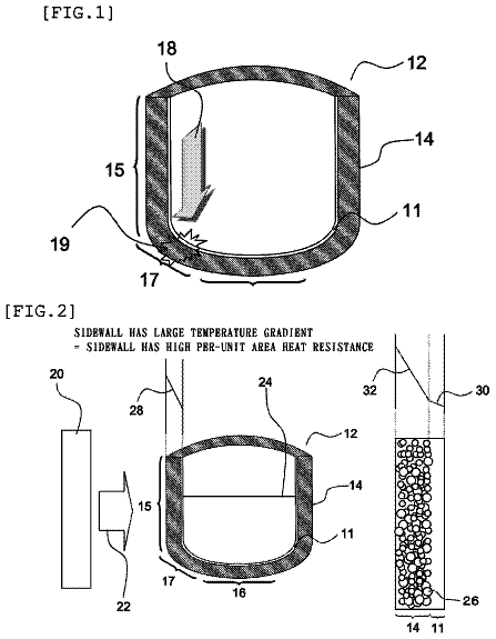
FIG. 1 is a cross-sectional view of a vitreous silica crucible, and a schematic diagram depicting a strain observation method.
FIG. 2 is electron microscope photos of the external appearance and cross sections of a plasma-treated synthetic silica powder of Manufacture Example 1.
FIG. 3 is electron microscope photos of the external appearance and cross sections of synthetic silica powder without plasma treatment of Comparative Manufacture Example 1.
FIG. 4 is Raman spectra of the plasma-treated synthetic silica powder of Manufacture Example 1.
FIG. 5 is a plot graph of the bubble content rates in respective parts of a vitreous silica crucible in Example 1 using the plasma-treated synthetic silica powder, and a vitreous silica crucible in Comparative Example 1 using the synthetic silica powder without plasma treatment.
FIG. 6 is a laser confocal microscope photo of the inner surface of the vitreous silica crucible in Example 1 using the plasma-treated synthetic silica powder.
FIG. 7 is a laser confocal microscope photo of the inner surface of the vitreous silica crucible in Comparative Example 1 using the synthetic silica powder without plasma treatment.
FIG. 8 is a polarized photo of a sliced section obtained by vertically slicing the vitreous silica crucible in Comparative Example 1 using the synthetic silica powder without plasma treatment.
FIG. 9 is a polarized photo of a sliced section obtained by vertically slicing the vitreous silica crucible in Example 1 using the plasma-treated synthetic silica powder.
FIG. 10 is a graph representing a distribution of residual stress from the inner surface of the vitreous silica crucible to the outer surface.
<Vitreous Silica Crucible>
A vitreous silica crucible according to the present invention comprises a substantially cylindrical straight body portion having an opening on the top end and extending in a vertical direction, a curved bottom portion, and a corner portion connecting the straight body portion with the bottom portion, and the curvature of which is greater than that of the bottom portion. The vitreous silica crucible comprises: a transparent layer on the inner surface side; a compressive stress layer which has compressive stress remaining in the inner surface side of the transparent layer, and a tensile stress layer which has tensile stress remaining and is adjacent to the opposite side to the inner surface layer at a gradual rate of change of stress with the compressive stress layer. Hereinafter, each component will be explained in detail.
The silica powder used for manufacturing a vitreous silica crucible includes crystallized natural silica powder and amorphous synthetic silica powder manufactured by chemical synthesis. The natural silica powder is silica powder manufactured by pulverizing natural mineral mainly consisting of α-quartz. The synthetic silica powder can be manufactured by means of chemical synthesis such as gas phase oxidation of silicon tetrachloride (SiCl.sub.4) (dry synthesis method), or hydrolysis of silicon alkoxide (Si(OR.sub.4)) (sol-gel method).
The vitreous silica crucible having an inner face layer (synthetic layer) vitrified from synthetic silica powder and an outer face layer (natural layer) vitrified from natural silica powder, is manufactured by supplying natural silica powder to a mold used for vitreous silica crucible, further supplying synthetic silica powder on the natural silica powder, and then melting the silica powders by Joule heat of arc discharge. In the initial stage of the arc melting process, bubbles are removed by subjecting the silica powder layer to a strong depressurization, thus a transparent vitreous silica layer (hereinafter referred to as “transparent layer”) is formed, and subsequently, a vitreous silica layer (hereafter, referred to as “bubble layer”) containing bubbles left by weakening the depressurization is formed. Here, the inner face layer formed from the synthetic silica powder is not necessarily the same as the transparent layer. Moreover, the outer face layer formed from the natural silica powder is not necessarily the same as the bubble layer.
In the present invention, the transparent layer is a layer formed on the inside of the vitreous silica crucible, and is substantially bubble-free. “Substantially bubble-free” means a bubble content rate and bubble diameter at such a degree that a yield of single crystal does not decrease due to the bubbles.
In the present invention, the compressive stress layer is a layer having compressive stress remaining on the inner surface side of the transparent layer.
In the present invention, the tensile stress layer is a layer having tensile stress therein which is adjacent to the compressive stress layer. The tensile stress layer is preferably present, for example, only in the transparent layer, at a ratio of preferably 90% or more, more preferably 95% or more, further preferably 100%, and is preferably not in the bubble layer. The ratio, for example, can be calculated by observing the change of stress in the wall thickness direction from the inner surface of the vitreous silica crucible.
As for the transparent layer, the residual stress from compressive to tensile has a value gradually sloping from the compressive stress to the tensile stress. The ratio of change of stress (rate of change of stress) is preferably 0.17 MPa/mm or more and 1.5 MPa/mm or less, for example, 0.17, 0.2, 0.3, 0.5, 0.7, 0.9, 1.1, 1.3, or 1.5 MPa/mm, and it can be in a range between any two numerical values exemplified here. When the rate of change of stress is less than 0.17 MPa/mm, tensile stress may reach the bubble layer. For this reason, in the bubble layer, fine crazes are likely to occur between bubbles, and then the fine crazes spread to form large cracks. When the rate of change of stress is less than 1.5 MPa/mm, the rate of change toward tensile stress from compressive stress is rapid, and a clear interface between the residual compressive stress and tensile stress can be observed. Therefore, stress concentrates in the interface, which results in a lack of a rim of the vitreous silica crucible and an inward sagging. Since no clear interface exists between the residual compressive stress and tensile stress when the stress changes gradually from the compressive stress to the tensile stress, the stress applied to the vitreous silica crucible is entirely distributed and defects in the vitreous silica crucible are prevented. Especially, as compared to a vitreous silica crucible with a small opening diameter, a vitreous silica crucible with a large opening diameter has a large degree of deformation with respect to external stress and thermal stress applied to the crucible and a high risk of damage. For this reason, for the vitreous silica crucible with a large opening diameter in which the change from the compressive stress to the tensile stress is gradual, it is capable of reducing the risk of damage.
A vitreous silica with stress remaining therein, shows anisotropy at the position where stress remains and an inward sagging occurs. The anisotropy of vitreous silica can be observed, as shown in FIG. 1 , by slicing the crucible vertically, placing the sliced crucible section between two polarizing plates combined in a crossed Nicol state, and observing it by passing white light. At this time, the sliced crucible section is polished to a thickness of about 2 mm. When no strain is present in the crucible piece, the crucible piece does not give an optical path difference for the white polarized light, so that the white polarized light which has passed through the crucible piece cannot pass through the crossed polarizing plates (analyzer). When strain is present in the crucible piece, the crucible piece gives an optical path difference for the white polarized light, so that the polarized plane of the white polarized light rotates, and the component that can pass through the crossed polarizing plates (analyzer) is observed. Because an optical path difference according to the strain is generated for each wavelength as the white polarized light passes through the crucible piece having strain, the amount of light passing through the polarizing plates is different for each wavelength. As a result, as for the crucible piece observed through the polarizing plates (analyzer), a color is observed. It is possible to evaluate the strain of the crucible section from the color. For example, by using the interference color chart or polarization color chart showing the relation between chromaticity and birefringence, the strain of the crucible piece can be evaluated and the stress can be calculated from the strain. Moreover, by using a sensitive color method, compressive stress or tensile stress can be determined depending on the color, so that the interface of the residual compressive stress and the residual tensile stress can be observed.
Moreover, by providing a ¼ wavelength plate between the crucible section sample and the detector, the stress of strain can be measured (Senarmont method). Specific measurement method is as follows. First, an analyzer is provided so as to be in a crossed Nicol state with respect to the polarizing plate (polarizer) placed in front of the light source. At this time, the rotating angle θ of the analyzer is 0 degrees. Next, the sample is observed from the analyzer side, and the sample is rotated with respect to the analyzer to make the sample portion to be stress measured become the brightest. Then, the analyzer is rotated horizontally to make the sample portion to be stress measured become the darkest. The stress can be calculated by substituting the rotating angle θ rotating from the brightest state to the darkest state into the following formula (2).
[ Formula 1 ] F = λ × θ 180 C × L ( 2 ) F: stress (MPa) λ: wavelength of the light source (nm) C: photoelastic constant (nm/cm)/MPa L: optical path length (cm) The photoelastic constant C of vitreous silica is 3.5±0.2 (nm/cm)/MPa. The wavelength of light source λ is selected to be a wavelength suitable for the ¼ wavelength to be used. With respect to the wavelength of the light source to be used, a suitable ¼ wavelength plate may be selected. The optical path length L is the thickness in the optical axis direction in the sample.
The change of stress from compressive stress to tensile stress can be calculated after plotting the stress F at any distance in the thickness direction from the inner surface of the crucible. Moreover, whether the change from compressive stress to tensile stress in the inner surface side is rapid or is gradual, can be determined by calculating an absolute value (rate of change of stress) of the inclination of the tangent to the interface (that is, the coordinate where stress is 0 MPa) in the distance-stress graph (X axis: distance from the inner surface, Y axis: stress). For example, when the absolute value of the inclination is 0.17 MPa/mm or more and 1.5 MPa/mm or less, the change of stress can be determined to be gradual.
For the conventional vitreous silica crucible, during the pulling of silicon single crystal the vitreous silica crucible has an inward sagging or a buckling, thus the yield of silicon single crystal may be reduced, and in some cases, the pulling of silicon single crystal is required to be stopped. In the vitreous silica crucible according to the present invention, the inner surface of the vitreous silica crucible is strengthened by residual compressive stress on the inner surface side of the transparent layer, and a change to tensile stress toward the outside at a gradual rate of change of stress is made so that the tensile stress remains in the transparent layer. When the tensile stress remains in the bubble layer, fine crazes are likely to generate between the bubbles, and the fine crazes become large cracks when spreading, which is necessary to be avoided. Therefore, it is preferable to have tensile stress remain in the transparent layer.
In the present invention, the bubble layer is formed on the outer side of the transparent layer. The bubble layer for example has a content rate of bubbles contained therein of 0.2% or more and 1% or less, and the average diameter of the bubbles is 20 μm or more and 200 μm or less.
The vitreous silica crucible according to the present invention preferably has a maximum bubble content rate of 0.10 Vol % or less. Furthermore, the vitreous silica crucible according to the present invention preferably has an average bubble diameter of 50 μm or less. When bubbles exist even slightly near the inner surface of the vitreous silica crucible, bubble-expansion occurs in the transparent layer during the pulling of silicon single crystal. The resulting bubbles intrude into the silicon melt with the melting of the inner face side of the transparent layer, and the bubbles are entrapped in the pulled silicon single crystal. The entrapped bubbles cause dislocation (crystal defects) due to crystalline transition, and reduce the yield of single crystal. Thus, when the maximum bubble content rate of the vitreous silica crucible is more than 0.10 Vol %, the reduction of yield of single crystal becomes significant. Moreover, when the average bubble diameter of the vitreous silica crucible is more than 50 μm, the expansion of bubbles causes a deformation of the vitreous silica crucible.
The bubbles existing near the inner surface of the vitreous silica crucible can be detected by using for example an optical detection unit. The optical detection unit includes a light-receiving apparatus which receives the transmitted light or reflected light of the light irradiated to a vitreous silica crucible. A light-emitting means of irradiation light may be integrated into the optical detection unit, and an external light-emitting means may also be utilized. Further, an optical detection unit being operated rotatably along the inner surface of the vitreous silica crucible is used. As the irradiation light, any light may be used as long as bubbles can be detected by the reflection of the light, and for example visible light, ultraviolet light, infrared light, and laser light are exemplified. The light-receiving apparatus is selected depending on the type of the irradiation light, and can be for example, a digital camera having an optical lens and an image pickup unit. Bubbles existing at a certain depth from the surface can be detected by moving the focus of the objective lens from the surface to the depth direction.
The measurement result obtained by the optical detection unit is input into an image processing device, and the bubble content rate P (%) is calculated. The image of the crucible inner surface is taken by use of an optical camera, and the crucible inner surface is divided based on a constant volume as a reference volume W1. A volume W2 occupied by bubbles is determined for the reference volume W1, and calculated by P (%)=(W2/W1)*100. The bubble content rate can be obtained by the volume of bubbles contained in the reference volume of the crucible, and the maximum bubble content rate can be the bubble content at the point having the highest value among the measured points. The maximum bubble content rate at a thickness from the crucible inner surface to the external surface direction of up to 0.3 mm, is preferred to be 0.05 Vol % or less.
At this time, the bubbles are measured to have a bubble diameter of 10 μm or more. When more than 0.05 Vol %, the reduction of yield of single crystal becomes significant. Moreover, since the reduction of yield of single crystal becomes significant when the maximum bubble diameter is more than 100 μm, the maximum bubble diameter is preferred to be 100 μm or less.
The average bubble diameter can be measured by calculating the average value of the diameters of spherical bubbles in the measuring range. The diameters can be calculated by software after obtaining an image of the vitreous sample.
Moreover, during the pulling of silicon single crystal, concavo-convex portions exist in the inner surface of the vitreous silica crucible, thus nonuniform cores are likely to generate. Foreign substance resulting from the growth of the core is sloughed off by corrosion and floats in the silicon melt, and thus adheres to the growing interface of the silicon single crystal being pulled up, so that a quality defect such as polycrystallization or dislocation occurs. The arithmetic average roughness (Ra) of the inner surface of the vitreous silica crucible is preferred to be 0.02 μm or less. In the case of more than 0.02 μm, the probability of generation of nonuniform cores increases, and the reduction of yield of single crystal becomes significant. From the roughness curve, a reference length is extracted in a direction of a mean line of the roughness curve, and the direction of the mean line in this extracted part is defined as an X axis, while a direction of a longitudinal magnification is defined as a Y axis, then a value integrated over the roughness curve with respect to the centerline is presented as the Ra in micrometers.
<Method for Manufacturing a Vitreous Silica Crucible>
Next, a method for manufacturing a vitreous silica crucible for pulling of silicon single crystal according to the present invention will be described.
First, a natural silica powder is supplied to a rotating mold for manufacturing a vitreous silica crucible, and a layer of the natural silica powder is formed in the inner face of the rotating mold for manufacturing the vitreous silica crucible. The natural silica powder can be manufactured by pulverizing natural mineral mainly consisting of α-quartz.
Next, a synthetic silica powder which satisfies following Formula
obtained by Raman measurement method is deposited on the inside of the layer of the natural silica powder. 0.8≦ R≦ 1.0
in Formula (1), intensity ratio R=(I.sub.1+I.sub.2)/I.sub.0 I.sub.1=peak intensity of Raman shift 492 cm.sup.−1 band I.sub.2=peak intensity of Raman shift 606 cm.sup.−1 band I.sub.0=peak intensity of Raman shift 800 cm.sup.−1 band
The measurement conditions of the Raman method can be: for example, wavelength: 532 nm; exposure time: 20 seconds; and cumulative number: 1 time. The Raman spectrum of the synthetic silica powder obtained from the condition is observed at characteristic peaks in Raman shift 492 cm.sup.−1 band, 606 cm.sup.−1 band and 800 cm.sup.−1 band, and each band responding to scattering peak of planar four-member ring (D1), scattering peak of planar three-member ring (D2), and scattering peak due to the fundamental vibration between silicon and oxygen, respectively. The peak intensity at each peak is the area at each peak. The peak area can be calculated by integrating the change in the electrical signal at the peak with time wherein a line connecting the falling point and the rising point of the peak is used as a base line. Further, as an example of other method, half-value method, triangular approximation method, and peak clipping method can be exemplified.
The intensity ratio R is 0.80 or more and 1.0 or less. The intensity ratio R may be, for example, 0.80, 0.85, 0.90, 0.95, 1.00, and may be within a range between any two of the numerical values exemplified herein. When the intensity ratio R is less than 0.80, the synthetic silica powder lacks planar three-member rings and planar four-member rings involved in a dense state, and a high dense state is not maintained in the synthetic silica powder. Such synthetic silica powder has small change in the vitreous structure during melting, the vitreous structure is likely to become uniform after melting, and the stress changes of compressive stress and tensile stress in the transparent layer are likely to become steep. On the contrary, when the intensity ratio R is more than 1.0, since a higher-density state due to the increase in the number of planar three-member rings and planar four-member rings is maintained in the synthetic silica powder, the change in vitreous structure during arc melting requires much time, and the stress changes of the compressive stress and the tensile stress in the transparent layer are likely to become steep.
A vitreous silica crucible manufacture using synthetic silica powder having an intensity ratio R of 0.80 or more and 1.0 or less enables both compressive stress and tensile stress to be remained in the transparent layer with a moderate difference in stress. Accordingly, the vitreous silica crucible without cracks, inward sagging, and buckling, even under a high temperature condition for a long-time, can be manufactured.
The circularity of the synthetic silica powder is preferably 0.73 or more and 1.0 or less. Because gaps between particles are small for synthetic silica powder having spheroid particles, the gaps are easily occupied during melting and the residuum of a gas component in the vitreous silica crucible can be prevented. When the circularity is less than 0.73, the gaps between the particles are large, so that the gaps are not occupied during melting and a gas component remains in the vitreous silica crucible, the bubble content rate may increase.
The circularity can be obtained, for example, as follows. First, the synthetic silica powder is dispersed into a liquid, which is then flowed through a planar elongational flow cell. 200 powder particles moving through the planar elongational flow cell are recorded as images by an objective lens, thereby from the recorded images a circularity is calculated by the following Formula (3). The measurement is performed twice, and the average value can be the circularity of the powder. Also, when the particles are perfect circles, the circularity is 1. circularity=4π S/L .sup.2
S: area of a particle in the projection view of the recorded image by photographing L: perimeter of a particle in the projection view
It is not necessary for all the synthetic silica powders for use to have a circularity of 0.73 or more and 1.0 or less, and the proportion of such silica particles is preferably 90% or more, more preferably 95% or more, further preferably 99% or more.
The synthetic silica powder preferably has an average particle diameter of 80 μm or more and 160 μm or less. The average particle diameter is, for example, 80, 85, 90, 95, 100, 110, 120, 130, 140, 150, or 160 μm, and it may be within a range between any two of the numerical values exemplified here. When the average particle diameter is 160 μm or less, since the spacing among the particles is small, it is possible to reduce the size of the bubbles in the vitreous silica crucible formed due to the entrainment of ambient gas. As a result, bubbles can be shrunk and eliminated during arc melting. However, when the average particle diameter is more than 160 μm, the size of spacing between the particles is large, thus the size of bubbles in the vitreous silica crucible formed due to the entrainment of ambient gas is large, and although the shrinking of bubbles during arc melting proceeds, the bubbles may not be eliminated. When the average particle diameter is less than 80 μm, degassing by evacuating is insufficient and bubbles may remain, because of the rapid melting by arc melting.
“Average particle diameter” means a particle diameter (D 50) at 50% cumulative value in the obtained particle size distribution, and means a volume average particle diameter in the present specification. For the measurement of the particle size distribution, a laser diffracting/scattering measurement method using laser light as a light source can be employed. “Particle size” is defined in a section of JIS Z 8901 “Powder Body for Test and Particle for Test.”
The synthetic silica powder preferably has a tapped bulk density of 1.35 g/cm.sup.3 μm or more and 1.44 g/cm.sup.3 or less. The tapped bulk density is, for example, 1.35, 1.38, 1.39, 1.40, 1.41, 1.42, 1.43, or 1.44 g/cm.sup.3, and it may be within a range between any two of the numeral values exemplified herein. When the tapped bulk density is less than 1.35 g/cm.sup.3, the bubble content rate may increase. This is presumably because gas is enclosed during melting because the spacing among particles is large. When the tapped bulk density is less than 1.44 g/cm.sup.3, degassing by evacuating is insufficient and bubbles become easy to remain.
The tapped bulk density can be obtained according to a density when the volume of the sample does not change after dispersing and filling the sample in a container and then applying impact to the container by tapping. For example, a tapping apparatus is provided to a measurement container having a sample therein and which bears an auxiliary cylinder, and tapping is performed 600 times. The mass is measured after leveling off the sample. The sample is supplemented again, and the tapping apparatus is provided to the measurement container with the auxiliary cylinder, and then tapping is performed 100 times. The mass is measured after leveling off the sample, and the performance is repeated until the mass difference from the previous mass is 0.3% or less. The mass of the sample is divided by the volume of the measurement container to obtain the tapped bulk density. It is possible to perform the measurement 3 times, and adopt the average value.
The synthetic silica powder preferably has a specific surface area of 0.026 m.sup.2/g or more and 0.045 m.sup.2/g or less. The specific surface area is, for example, 0.026, 0.028, 0.030, 0.032, 0.034, 0.036, 0.038, 0.040, or 0.045 m.sup.2/g, and it can be within a range between any two of numeral values exemplified here. When the specific surface area is more than 0.045 m.sup.2/g, gas existing on the flaw or crack surface is entrapped during melting, and remains as bubbles; thus the bubble content rate is raised. On the other hand, when the specific surface area is less than 0.026 m.sup.2/g, gas existing in the central portion of the silica particle can be prevented from coming out of the surface during melting. From this, it is preferable that depressions exist on the surface to some extent so that the bubble content rate can be reduced.
Specific surface area can be obtained by a nitrogen adsorption method. The nitrogen adsorption method includes:
adsorbing nitrogen gas to the synthetic silica powder while increasing pressure gradually from a high vacuum;
creating an adsorption isotherm by plotting the relative pressure to the X axis, the amount of nitrogen adsorbed to the Y axis;
determining the specific surface area by applying the data of the adsorption isotherm to various adsorption isotherm formulas. As the adsorption isotherm, for example, Henry adsorption isotherm formula, Langmuir adsorption isotherm formula, and BET adsorption isotherm formula can be mentioned.
It is not necessary for all the synthetic silica powder for use to have a specific surface area of 0.026 m.sup.2/g or more and 0.045 m.sup.2/g or less, and the proportion of such silica particles is preferably 90% or more, more preferably 95% or more, further preferably 99% or more.
The synthetic silica powder to be used in the present invention can be manufactured by, for example, subjecting the synthetic silica powder material to a plasma treatment, subsequently to a treatment at a cooling speed of 10.sup.5 K/min or more. The synthetic silica powder material can be manufactured by means of chemical synthesis such as gas phase oxidation of silicon tetrachloride (SiCl.sub.4) (dry synthesis method), or hydrolysis of silicon alkoxide (Si(OR.sub.4)) (sol-gel method).
The description continues in the full USPTO document.
About 6,345 words. The USPTO PDF has it with every drawing.
Fees are due 3.5, 7.5 and 11.5 years after grant. This patent expired on September 12, 2025, so the fee marked "not paid" was the one that went unpaid.
VITREOUS SILICA CRUCIBLE FOR PULLING OF SILICON SINGLE CRYSTAL AND METHOD FOR MANUFACTURING THE SAME
Filed May 2013 · published Apr 2016Vitreous silica crucible for pulling of silicon single crystal and method for manufacturing the same
Filed May 2013 · granted Sep 2017Earlier publications, parents and continuations. None of them can still be enforced, or this patent would not be listed.
Prior art cited by the examiner or applicant. Useful when you check your own idea for novelty.
Everything on this page comes from the documents linked above.