Technical field
The present invention relates to video processing, and more particularly, to method and device for intra-predicting a depth image.
Background art
Digital broadcast services using a 3D video have attracted attention as a next-generation broadcast service. A 3D video can provided a sense of realism and a sense of immersion using plural viewpoint channels. Examples of the 3D video providing a three-dimensional effect include a binocular 3D video, a multi-view 3D video, and a hologram.
In a 3D video, a depth image as well as a texture image can be encoded and/or decoded, unlike existing 2D videos. Unlike a texture image which is a video compression standard target in the related art, a depth image may include depth information of objects in a screen. The three-dimensional effect of a 3D video can be expressed by the depth information. SUMMARY OF THE INVENTION Technical Problem
An object of the present invention is to provide video encoding method and device which can enhance encoding/decoding efficiency of a video.
Another object of the present invention is to provide video decoding method and device which can enhance encoding/decoding efficiency of a video.
Still another object of the present invention is to provide intra prediction method and device which can enhance encoding/decoding efficiency of a video.
Still another object of the present invention is to provide video information transmitting method and device which can enhance encoding/decoding efficiency of a video. Solution to Problem
According to an aspect of the present invention, there is provided an intra prediction method of predicting pixel values in a prediction target block on the basis of plural neighboring pixels adjacent to the prediction target block. The intra prediction method includes: receiving and decoding encoded video information; determining a target boundary by determining a plurality of boundary pixels indicating the target boundary in the prediction target block on the basis of the decoded video information; determining a plurality of prediction target regions into which the prediction target block is split by the target boundary; and performing a prediction process on the plurality of prediction target regions on the basis of different neighboring pixels out of the plurality of neighboring pixels.
The prediction target block may be one block of a plurality of blocks constituting a depth image of a 3D video.
The plurality of boundary pixels may include N boundary pixels {p.sub.0, p.sub.1, . . . p.sub.n, . . . p.sub.N-1}, N may be a positive integer, n may be an integer of 0 to N−1, and the boundary pixel p.sub.n may be sequentially determined along a progress direction from the boundary pixel p.sub.n−1.
The received video information may include position information indicating a position of a start boundary pixel p.sub.0 which is first determined out of the plurality of boundary pixels, and the step of determining the target boundary may include determining the start boundary pixel p.sub.0 on the basis of the position information.
The start boundary pixel p.sub.0 may be a pixel located at the leftmost position or the uppermost position in the prediction target block.
The video information may include information on a chain code corresponding to the boundary pixel p.sub.n, the chain code may indicate an angle between a first progress direction from the boundary pixel p.sub.n−1 to the boundary pixel p.sub.n and a second progress direction from the boundary pixel p.sub.n to the boundary pixel p.sub.n+1, and the step of determining the target boundary may include determining a partial boundary corresponding to a part adjacent to the boundary pixel p.sub.n in the target boundary on the basis of the first progress direction and the second progress direction.
The angle may be one of 0 degrees, 45 degrees, −45 degrees, 90 degrees, −90 degrees, 135 degrees, and −135 degrees.
The step of determining the target boundary may include determining the position of the boundary pixel p.sub.n+1 on the basis of the first progress direction and the second progress direction.
The boundary pixel p.sub.n may correspond to the start boundary pixel p.sub.0. In this case, the first progress direction may be set to a right horizontal direction when the boundary pixel p.sub.n is a pixel located at the leftmost position in the prediction target block, and the first progress direction may be set to a lower vertical direction when the boundary pixel p.sub.n is a pixel located at the uppermost position in the prediction target block.
The boundary pixel p.sub.N-1 may be an end boundary pixel which is finally determined out of the plurality of boundary pixels, and the step of determining the target boundary may include determining a partial boundary corresponding to a part adjacent to the end boundary pixel p.sub.N-1 in the target boundary on the basis of the progress direction from the boundary pixel p.sub.N-2 to the end boundary pixel p.sub.N-1.
The plurality of prediction target regions may include M prediction target regions R.sub.0, R.sub.1, . . . , R.sub.m, . . . , and R.sub.M-1, M is a positive integer, and m is an integer of 0 to M−1, and the step of performing the prediction process may include performing a prediction process on the prediction target region R.sub.m on the basis of the neighboring pixels adjacent to the prediction target region R.sub.m out of the plurality of neighboring pixels.
The step of performing the prediction process may include determining an average pixel value of the neighboring pixels adjacent to the prediction target region R.sub.m as predicted values of the pixels belonging to the prediction target region R.sub.m.
According to another aspect of the present invention, there is provided a video decoder. The video decoder includes: a receiver module that receives video information; a prediction module that constructs a predicted block corresponding to a prediction target block by predicting pixel values in the prediction target block on the basis of a plurality of neighboring pixels adjacent to the prediction target block; and a reconstructed block constructing module that constructs a reconstructed block on the basis of the predicted block, wherein the prediction module determines a target boundary by determining a plurality of boundary pixels indicating the target boundary in the prediction target block on the basis of the decoded video information, and performs a prediction process on a plurality of prediction target regions, into which the prediction target block is split by the target boundary, on the basis of different neighboring pixels out of the plurality of neighboring pixels.
According to still another aspect of the present invention, there is provided a video decoding method. The video decoding method includes the steps of: receiving and decoding encoded video information; determining a target boundary by determining a plurality of boundary pixels indicating the target boundary in the prediction target block on the basis of the decoded video information; determining a plurality of prediction target regions into which the prediction target block is split by the target boundary; constructing a predicted block corresponding to the prediction target block by performing a prediction process on the plurality of prediction target regions on the basis of different neighboring pixels out of the plurality of neighboring pixels adjacent to the prediction target block; and constructing a reconstructed block on the basis of the predicted block.
The prediction target block may be one block of a plurality of blocks constituting a depth image of a 3D video.
The plurality of boundary pixels may include N boundary pixels {p.sub.0, p.sub.1, . . . , p.sub.n, . . . , p.sub.N-1}, N may be a positive integer, n may be an integer of 0 to N−1, and the boundary pixel p.sub.n may be sequentially determined along a progress direction from the boundary pixel p.sub.n−1.
The received video information may include position information indicating a position of a start boundary pixel p.sub.0 which is first determined out of the plurality of boundary pixels, and the step of determining the target boundary may include determining the start boundary pixel p.sub.0 on the basis of the position information.
The video information may include information on a chain code corresponding to the boundary pixel p.sub.n, the chain code may indicate an angle between a first progress direction from the boundary pixel p.sub.n−1 to the boundary pixel p.sub.n and a second progress direction from the boundary pixel p.sub.n to the boundary pixel p.sub.n+1, and the step of determining the target boundary may include determining a partial boundary corresponding to a part adjacent to the boundary pixel p.sub.n in the target boundary on the basis of the first progress direction and the second progress direction.
The plurality of prediction target regions may include M prediction target regions R.sub.0, R.sub.1, . . . , R.sub.m, . . . , and R.sub.M-1, M may be a positive integer, m may be an integer of 0 to M−1, and the step of constructing the predicted block may include performing a prediction process on the prediction target region R.sub.m on the basis of the neighboring pixels adjacent to the prediction target region R.sub.m out of the plurality of neighboring pixels.
The step of constructing the predicted block may include determining an average pixel value of the neighboring pixels adjacent to the prediction target region R.sub.m as predicted values of the pixels belonging to the prediction target region R.sub.m. Advantageous Effects
By employing the video encoding method according to the present invention, it is possible to enhance encoding/decoding efficiency of a video.
By employing the video decoding method according to the present invention, it is possible to enhance encoding/decoding efficiency of a video.
By employing the intra prediction method according to the present invention, it is possible to enhance encoding/decoding efficiency of a video.
By employing the video information transmitting method according to the present invention, it is possible to enhance encoding/decoding efficiency of a video.
Brief description of the drawings
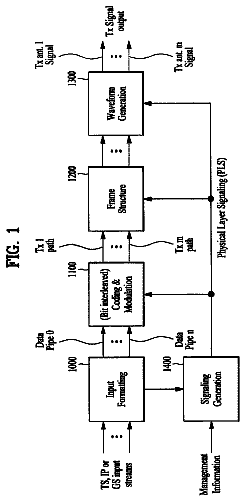
FIG. 1 is a block diagram schematically illustrating a video encoder according to an embodiment of the present invention.
FIG. 2 is a conceptual diagram schematically illustrating a prediction module according to an embodiment of the present invention.
FIG. 3 is a block diagram schematically illustrating a video decoder according to an embodiment of the present invention.
FIG. 4 is a conceptual diagram schematically illustrating a prediction module of the video decoder according to the embodiment of the present invention.
FIG. 5 is a diagram illustrating an intra prediction mode deriving method based on an MPM and a remaining mode.
FIG. 6 is a diagram schematically illustrating characteristics of a depth image of a 3D video.
FIG. 7 is a diagram schematically illustrating an example of a method of encoding information on boundary pixels constituting a boundary pixel chain.
FIG. 8 is a diagram schematically illustrating an example of a method of deriving a chain code when a boundary pixel corresponding to information to be currently encoded is a start boundary pixel.
FIG. 9 is a diagram schematically illustrating an example of a method of determining a pixel boundary on the basis of the chain code of the boundary pixels.
FIG. 10 is a diagram schematically illustrating another example of the method of determining a pixel boundary on the basis of the chain code of the boundary pixels.
FIG. 11 is a diagram illustrating an example of a method of determining a pixel boundary of an end boundary pixel.
FIG. 12 is a diagram schematically illustrating an example of a method of performing an intra prediction process on regions in a prediction target block.
FIG. 13 is a diagram schematically illustrating another example of the method of performing an intra prediction process on regions in a prediction target block.
FIG. 14 is a diagram schematically illustrating an example of a method of performing an intra prediction process on regions in a prediction target block.
FIG. 15 is a flowchart schematically illustrating an example of a process performed by an encoder when a boundary intra prediction mode is used.
FIG. 16 is a flowchart schematically illustrating an example of an intra prediction method performed by a decoder when a boundary intra prediction mode is used.
FIG. 17 is a block diagram schematically illustrating an example of a video decoder according to an embodiment of the present invention.
FIGS. 18 a to 18 c are diagrams schematically illustrating an example of an intra prediction process using a boundary intra prediction mode according to the present invention.
Description of embodiments
The invention may be variously modified in various forms and may have various embodiments, and specific embodiments thereof will be illustrated in the drawings and described in detail. However, these embodiments are not intended for limiting the invention. Terms used in the below description are used to merely describe specific embodiments, but are not intended for limiting the technical spirit of the invention. An expression of a singular number includes an expression of a plural number, so long as it is clearly read differently. Terms such as “include” and “have” in this description are intended for indicating that features, numbers, steps, operations, elements, components, or combinations thereof used in the below description exist, and it should be thus understood that the possibility of existence or addition of one or more different features, numbers, steps, operations, elements, components, or combinations thereof is not excluded.
On the other hand, elements of the drawings described in the invention are independently drawn for the purpose of convenience of explanation on different specific functions in an image encoder and an image decoder, and do not mean that the elements are embodied by independent hardware or independent software. For example, two or more elements out of the elements may be combined to form a single element, or one element may be split into plural elements. Embodiments in which the elements are combined and/or split belong to the scope of the invention without departing from the concept of the invention.
Some elements may not be essential elements for performing essential functions of the invention but may be selective elements for merely improving performance. The invention may be embodied by only the elements essential to embody the invention, other than the elements used to merely improve performance, and a structure including only the essential elements other than the selective elements used to merely improve performance belongs to the scope of the invention.
Hereinafter, exemplary embodiments of the invention will be described in detail with reference to the accompanying drawings. The same elements in the drawings will be referenced by the same reference signs and the description of the same elements will not be repeated.
FIG. 1 is a block diagram schematically illustrating a video encoder according to an embodiment of the present invention.
In a 3D video, a depth image as well as a texture image can be encoded and/or decoded, unlike existing 2D videos. Unlike a texture image which is a video compression standard target in the related art, a depth image may include depth information of objects in a screen. The three-dimensional effect of a 3D video can be expressed by the depth information. The video encoder illustrated in FIG. 1 can be applied to a texture image and a depth image.
Referring to FIG. 1 , a video encoder 100 includes a picture splitting module 105 , a prediction module 110 , a transform module 115 , a quantization module 120 , a rearrangement module 125 , an entropy encoding module 130 , a dequantization module 135 , an inverse transform module 140 , a filter module 145 , and a memory 150 .
The picture splitting module 105 may split an input picture into at least one process unit. The input picture may be a texture picture of a texture image or a depth picture of a depth image. Here, the process unit may be a prediction unit (PU), a transform unit (TU), or a coding unit (CU). Embodiments will be described below based on process units which are created by splitting an encoding/decoding target picture (or a current picture) and units may be referred to as blocks in some cases. In the below description, a block acquired by splitting a texture picture is referred to as a texture block and a block acquired by splitting a depth picture is referred to as a depth block.
The prediction module 110 may include an inter prediction module that performs an inter prediction process and an intra prediction module that performs an intra prediction process, as will be described later. The prediction module 110 may perform a prediction process on the prediction unit supplied from the picture splitting module 105 to construct a predicted block. The process unit of a picture in the prediction module 110 may be a coding unit, a transform unit, or a prediction unit. It may be determined whether the prediction process performed on the process unit is inter prediction or intra prediction and specific details (for example, a prediction mode) of the determined prediction method may be determined. Here, the process unit on which the prediction process is performed may be different from the process unit of which the specific details are determined. For example, the prediction method and the prediction mode may be determined by prediction units, and the prediction process may be performed by transform units. A residual value (residual block) between the constructed predicted block and the original block may be input to the transform module 115 . Prediction mode information, motion vector information, and the like used for the prediction along with residual value may be encoded and transmitted to a decoder by the entropy encoding module 130 .
The transform module 115 may transform the residual block by units of transform and may construct transform coefficients. The unit of transform in the transform module 115 may be a transform unit and may have a quad tree structure. At this time, the size of the transform unit may be determined within a range including a predetermined largest size and a predetermined minimum size. The transform module 115 may transform the residual block using a DCT (Discrete Cosine Transform) and/or a DST (Discrete Sine Transform).
The quantization module 120 may quantize the residual values transformed by the transform module 115 and may create quantization coefficients. The values calculated by the quantization module 120 may be supplied to the dequantization module 135 and the rearrangement module 125 .
The rearrangement module 125 may rearrange the quantization coefficients supplied from the quantization module 120 . By rearranging the quantization coefficients, it is possible to enhance the coding efficiency in the entropy encoding module 130 . The rearrangement module 125 may rearrange the quantization coefficients in the form of a two-dimensional block to the form of a one-dimensional vector through the use of a coefficient scanning method. The rearrangement module 125 may enhance the entropy encoding efficiency in the entropy encoding module 130 by changing the order of coefficient scanning on the basis of stochastic statistics of the coefficients transmitted from the quantization module.
The entropy encoding module 130 may perform an entropy encoding process on the quantization coefficients rearranged by the rearrangement module 125 . The entropy encoding module 130 may encode a variety of information such as quantization coefficient information of a coding unit, block type information, prediction mode information, split unit information, prediction unit information, transfer unit information, motion vector information, reference picture information, block interpolation information, and filtering information which are transmitted from the rearrangement module 125 and the prediction module 110 .
Entropy encoding methods such as an exponential golomb method, a CAVLC (Context-Adaptive Variable Length Coding) method, and/or a CABAC (Context-Adaptive Binary Arithmetic Coding) method may be used for the entropy encoding. For example, a table used to perform the entropy encoding process such as a variable length coding (hereinafter, referred to as “VLC”) table may be stored in the entropy encoding module 130 . The entropy encoding module 130 may perform the entropy encoding process using the stored VLC table. For example, in the CABAC entropy encoding method, the entropy encoding module 130 may binarize a symbol, convert the binarized symbol into bins, and then perform an arithmetic encoding process on the bins depending on occurrence probabilities of the bins to create a bitstream.
When the entropy encoding is used, a low index and a short codeword corresponding thereto may be allocated to a symbol of a high occurrence probability, and a high index and a long codeword corresponding thereto may be allocated to a symbol of a low occurrence probability. Therefore, it is possible to reduce the bit rate of the symbols to be encoded and to improve video compression performance by the entropy encoding.
The dequantization module 135 dequantizes the values quantized by the quantization module 120 . The inverse transform module 140 inversely transforms the values dequantized by the dequantization module 135 . The residual value created by the dequantization module 135 and the inverse transform module 140 may be merged with the predicted block predicted by the prediction module 110 to construct a reconstructed block.
The filter module 145 may apply an in-loop filter to the reconstructed block and/or picture. The in-loop filter may include a deblocking filter, a sample adaptive offset (SAO), and/or an adaptive loop filter (ALF).
The deblocking filter may remove a block distortion generated at the boundary between blocks in the reconstructed picture. The SAO may an appropriate offset value to pixel values so as to compensate for a coding error. The ALF may perform a filtering process on the basis of the resultant values of comparison of the original picture with the reconstructed picture of which the blocks have been filtered by the deblocking filter.
On the other hand, the filter module 145 may not perform a filtering process on the reconstructed block used for the intra prediction.
The memory 150 may store the reconstructed block or picture calculated by the filter module 145 . The reconstructed block or picture stored in the memory 150 may be supplied to the prediction module 110 that performs the inter prediction.
FIG. 2 is a conceptual diagram schematically illustrating a prediction module according to an embodiment of the present invention. Referring to FIG. 2 , the prediction module 200 includes an inter prediction module 210 and an intra prediction module 220 .
The inter prediction module 210 may perform a prediction process on the basis of information of at least one picture out of a previous picture and a subsequent picture of a current picture and may construct a predicted block. The intra prediction module 220 may perform a prediction process on the basis of information of pixels in the current picture and may construct a predicted block.
The intra prediction may be performed depending on an intra prediction mode of a prediction target block. The number of possible intra prediction modes of a prediction target block may be a predetermined fixed value. Examples of the intra prediction mode include a vertical mode, a horizontal mode, a DC mode, a planar mode, and angular modes depending on the positions and the prediction methods of reference pixels used to predict the pixel values of the current block. In the vertical mode, the prediction process may be performed in the vertical direction using the pixel values of neighboring blocks. In the horizontal mode, the prediction process may be performed in the horizontal direction using the pixel values of neighboring blocks. In the DC mode, a predicted block may be constructed by averaging the pixel values of the reference pixels. In the planar mode, a pixel value at a predetermined position in the current block may be first predicted and then the pixel values at the other positions in the current block may be predicted on the basis thereof. In the angular modes, the prediction process may be performed depending on an angle and/or direction pre-determined for each mode.
When the prediction target block corresponds to a depth block, a boundary intra prediction mode to be described later may be used for the intra prediction of the prediction target block. When the boundary intra prediction mode is used, for example, information on the boundary intra prediction mode may be encoded by the entropy encoding module 130 illustrated in FIG. 1 and may be transmitted to the decoder. For example, the information on the boundary intra prediction mode may be encoded by a particular device other than the entropy encoding module 130 illustrated in FIG. 1 and may be transmitted. At this time, the information on the boundary intra prediction mode may be defined in a head other than the header including information on other intra prediction mode such as the vertical mode, the horizontal mode, the DC mode, the planar mode, and the angular modes and may be processed through the use of a particular process.
FIG. 3 is a block diagram schematically illustrating a video decoder according to an embodiment of the present invention. Referring to FIG. 3 , the video decoder 300 includes an entropy decoding module 310 , a rearrangement module 315 , a dequantization module 320 , an inverse transform module 325 , a prediction module 330 , a filter module 335 , and a memory 340 . The video decoder illustrated in FIG. 3 may be applied to a texture image and a depth image, similarly to the video encoder.
When a video bitstream is input to the video decoder, the input bitstream may be decoded on the basis of the order in which video information is processed by the video encoder. At this time, the input bitstream may be a bitstream corresponding to a texture image or a bitstream corresponding to a depth image.
The entropy decoding module 310 may perform an entropy decoding process on the input bitstream, and the entropy decoding method is similar to the above-mentioned entropy encoding method. For example, when the entropy decoding is applied, a low index and a short codeword corresponding thereto may be allocated to a symbol of a high occurrence probability, and a high index and a long codeword corresponding thereto may be allocated to a symbol of a low occurrence probability. Therefore, it is possible to reduce the bit rate of the symbols to be encoded and to improve video compression performance by the entropy coding.
Information for constructing a predicted block out of the information decoded by the entropy decoding module 310 may be supplied to the prediction module 330 , and the residual value entropy-decoded by the entropy decoding module may be input to the rearrangement module 315 .
The rearrangement module 315 may rearrange the bitstream entropy-decoded by the entropy decoding module 310 on the basis of the rearrangement method used in the video encoder. The rearrangement module 315 may reconstruct and rearrange coefficients expressed in the form of a one-dimensional vector into coefficients in the form of a two-dimensional block. The rearrangement module 315 may be supplied with information associated with the coefficient scanning performed by the video encoder and may perform the rearrangement using a method of inversely scanning the coefficients on the basis of the scanning order in which the scanning is performed by the entropy encoding module.
The dequantization module 320 may perform dequantization on the basis of the quantization parameters supplied from the video encoder and the coefficient values of the rearranged block.
The inverse transform module 325 may perform the inverse DCT and/or inverse DST of the DCT and/or DST, which has been performed by the transform module of the video encoder, on the quantization result from the video encoder. The inverse transform may be performed on the basis of a transfer unit determined by the video encoder or a split unit of a picture. The transform module of the video encoder may selectively perform the DCT and/or DST depending on plural information pieces such as the prediction method, the size of a current block, and the prediction direction, and the inverse transform module 325 of the video decoder may perform the inverse transform on the basis of the transform information on the transform performed by the transform module of the video encoder.
The prediction module 330 may construct a predicted block on the basis of predicted block construction information supplied from the entropy decoding module 310 and the previously-decoded block and/or picture information supplied from the memory 340 . The reconstructed block may be constructed using the predicted block constructed by the prediction module 330 and the residual block supplied from the inverse transform module 325 .
The reconstructed block and/or picture may be supplied to the filter module 335 . The filter module 335 may apply an in-loop filter to the reconstructed block and/or picture. The in-loop filter may include a deblocking filter, a sample adaptive offset (SAO), and/or an adaptive loop filter (ALF).
The memory 340 may store the reconstructed picture or block for use as a reference picture or a reference block and may supply the reconstructed picture to an output module.
FIG. 4 is a conceptual diagram schematically illustrating the prediction module of the video decoder according to the embodiment of the invention. Referring to FIG. 4 , the prediction module 400 includes an intra prediction module 410 and an inter prediction module 420 .
The intra prediction module 410 may construct a predicted block on the basis of pixel information in a current picture, when the prediction mode of a prediction unit is an intra prediction mode.
As described above, the intra prediction may be performed depending on the intra prediction mode of a prediction target block. The number of possible intra prediction modes of a prediction target block may be a predetermined fixed value. Examples of the intra prediction mode include a vertical mode, a horizontal mode, a DC mode, a planar mode, and angular modes. When a prediction target block corresponds to a depth block, a boundary intra prediction mode to be described later may be applied to the intra prediction of the prediction target block. At this time, the intra prediction module 410 may perform the intra prediction on the prediction target block on the basis of information on the boundary intra prediction mode received from the video encoder. For example, the information on the boundary intra prediction mode from the video encoder may be information encoded by the entropy encoding module 130 illustrated in FIG. 1 . At this time, the encoded information on the boundary intra prediction mode may be decoded by the entropy decoding module 310 and may be used for the intra prediction. For example, the information on the boundary intra prediction mode may be decoded by a particular device other than the entropy decoding module 310 illustrated in FIG. 3 and may be input to the intra prediction module 410 . At this time, the information on the boundary intra prediction mode may be defined in a head other than the header including information on other intra prediction mode such as the vertical mode, the horizontal mode, the DC mode, the planar mode, and the angular modes and may be processed through the use of a particular process.
The inter prediction module 420 may perform an inter prediction process on a current prediction unit on the basis of the information included in at least one picture out of a previous picture or a subsequent picture of a current picture including the current prediction unit using information necessary for inter prediction of the current prediction unit which is supplied from the video encoder, for example, information on the motion vector and the reference picture index, when the prediction mode of the corresponding prediction unit is an inter prediction mode.
Hereinafter, when a “video” or a “screen” has the same meaning as a “picture” in some configurations or expressions of the invention, a “picture” may be described as a “video” or a “screen”.
As described above with reference to FIGS. 2 and 4 , the intra prediction module 220 of the video encoder and the intra prediction module 420 of the video decoder may perform the intra prediction depending on the intra prediction mode of a prediction target block. At this time, the video encoder may transmit the intra prediction mode information used for prediction to the video decoder and the video decoder may determine the intra prediction mode on the basis of the transmitted information. Infra prediction mode information may be transmitted as a value itself indicating the prediction mode, but a method of transmitting the intra prediction mode information using a predicted mode value of the intra prediction mode may be used to improve the transmission efficiency. Hereinafter, a predicted mode of a current intra prediction mode is referred to as a most probable mode (MPM).
FIG. 5 is a diagram illustrating an intra prediction mode deriving method based on an MPM and a remaining mode.
In the example illustrated in FIG. 5 , a prediction target block may mean a block on which a prediction process is currently performed. Hereinafter, the prediction mode of the prediction target block in the example illustrated in FIG. 5 is referred to as a current prediction mode and the mode value of the current prediction mode is referred to as a current mode value.
In FIG. 5 , A represents an upper neighboring block adjacent to the top of a prediction target block and B represents a left neighboring block adjacent to the left side of the prediction target block. The upper neighboring block A, the left neighboring block B, and the prediction target block may have the same size as illustrated in FIG. 5 , or may have different sizes.
Referring to FIG. 5 , the intra prediction module may construct an MPM candidate list on the basis of the prediction mode (mode A) of the upper neighboring block A and the prediction mode (mode B) of the left neighboring block B. Here, the number of MPM candidates constituting the MPM candidate list may be a fixed value. For example, the fixed value may be 3. For example, when it is assumed that three MPM candidates are always used in the example illustrated in FIG. 5 and mode A and mode B are equal to each other, the number of MPM candidates derived may be 1 and thus the other MPM candidates may be set to the DC mode, the planar mode, or other predetermined prediction modes.
The intra prediction mode of a prediction target block may be the same prediction mode as one of the MPM candidates. Information on whether a candidate having the same prediction mode as the prediction target block is present in the MPM candidates may be transmitted from the video encoder to the video decoder via an MPM flag indicating the information. The MPM flag may be, for example, prev_intra_luma_pred_flag. When the flag is 1, a candidate having the same prediction mode as the prediction target block may be present in the MPM candidates.
When the flag is 1 and the number of MPM candidates is 2 or more, the video encoder may transmit an MPM index indicating whether the prediction mode of the prediction target block is equal to which prediction mode of the MPM candidates. The decoder may determine the prediction mode of the prediction target block on the basis of the MPM index. For example, the MPM index may be expressed by mpm_idx.
When all the prediction modes of the MPM candidates are different from the prediction mode of the prediction target block, for example, when the value of the flag indicating whether a candidate having the same prediction mode as the prediction target block is present in the MPM candidates is 0, the video encoder may transmit intra prediction mode information of the prediction target block to the decoder using a remaining mode.
When all the prediction modes of the MPM candidates are different from the current prediction mode, the video encoder may transmit the information on the current prediction mode out of the prediction modes other than the MPM candidates to the video decoder. Here, the video encoder may transmit the prediction mode information using the current mode value when the mode values of all the MPM candidates are greater than the current mode value, and may transmit the prediction mode information using a value obtained by subtracting the number of MPM candidates having a mode value smaller than the current mode value from the current mode value when an MPM candidate having a mode value smaller than the current mode value is present. Here, a prediction mode having a mode value obtained by subtracting the number of MPM candidates having a mode value smaller than the current mode value from the current mode value may be referred to as a remaining mode. For example, the remaining mode may be expressed by rem_intra_luma_pred_mode.
The video decoder may know that a candidate having the same prediction mode as the prediction target block is not present in the MPM candidates through the use of the flag information such as prev_intra_luma_pred_flag.
Here, the decoder may calculate an actual prediction mode value of the current prediction unit using the remaining mode and the MPM. For example, it is assumed that the number of MPMs is N and the mode values of the MPM are mode1, mode2, . . . , modeN. Here, it is assumed that the smaller the X value modeX is, the smaller mode value is allocated. When X ranges from 1 to N−1 and the mode value of the remaining mode is greater than or equal to modeX−(X−1) and smaller than mode(X+1)−X, a value obtained by adding X to the mode value of the remaining mode may be the current prediction mode. When X is N and the mode value of the remaining mode is greater than or equal to modeN−(N−1), a value obtained by adding N to the mode value of the remaining mode may be the current prediction mode.
When the remaining mode is used, it is possible to reduce the bit rate necessary for transmitting the intra prediction mode of the prediction target block and thus to enhance the coding efficiency.
In the above-mentioned embodiment, information on the intra prediction mode transmitted from the video encoder to the video decoder for each prediction unit can be expressed by syntax elements shown in Table 1.
TABLE-US-00001 TABLE 1 prediction_unit( ) { ... prev_intra_luma_pred_flag[ x0 ][ y0 ] if( prev_intra_luma_pred_flag[ x0 ][ y0 ] ) if( NumMPMCand > 1 ) mpm_idx[ x0 ][ y0 ] else rem_intra_luma_pred_mode[ x0 ][ y0 ] if( IntraPredMode[ x0 ][ y0 ] == 2 ) planar_flag_luma[ x0 ][ y0 ] ... }
Here, prev_intra_luma_pred_flag represents the MPM flag and NumMPMCand represents the number of MPM candidates in the MPM list. In addition, mpm_idx represents the MPM index, and rem_intra_luma_pred_mode represents the remaining mode. IntraPredMode represents an intra prediction mode, and planar_flag_luma is a flag indicating whether the intra prediction mode of a current prediction unit is a planar mode.
The description continues in the full USPTO document.
 Lapsed, fee not paid15 drawings